1998 OPEL FRONTERA direction
[x] Cancel search: directionPage 1371 of 6000

6E–254
ENGINE DRIVEABILITY AND EMISSIONS
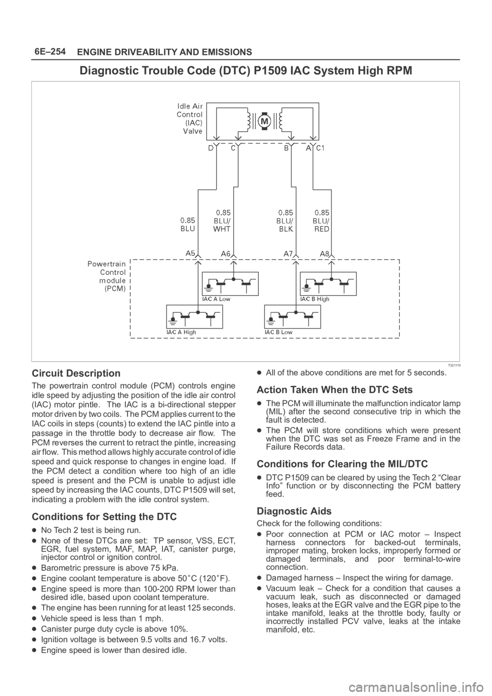
Diagnostic Trouble Code (DTC) P1509 IAC System High RPM
T321115
Circuit Description
The powertrain control module (PCM) controls engine
idle speed by adjusting the position of the idle air control
(IAC) motor pintle. The IAC is a bi-directional stepper
motor driven by two coils. The PCM applies current to the
IAC coils in steps (counts) to extend the IAC pintle into a
passage in the throttle body to decrease air flow. The
PCM reverses the current to retract the pintle, increasing
air flow. This method allows highly accurate control of idle
speed and quick response to changes in engine load. If
the PCM detect a condition where too high of an idle
speed is present and the PCM is unable to adjust idle
speed by increasing the IAC counts, DTC P1509 will set,
indicating a problem with the idle control system.
Conditions for Setting the DTC
No Tech 2 test is being run.
None of these DTCs are set: TP sensor, VSS, ECT,
EGR, fuel system, MAF, MAP, IAT, canister purge,
injector control or ignition control.
Barometric pressure is above 75 kPa.
Engine coolant temperature is above 50C (120F).
Engine speed is more than 100-200 RPM lower than
desired idle, based upon coolant temperature.
The engine has been running for at least 125 seconds.
Vehicle speed is less than 1 mph.
Canister purge duty cycle is above 10%.
Ignition voltage is between 9.5 volts and 16.7 volts.
Engine speed is lower than desired idle.
All of the above conditions are met for 5 seconds.
Action Taken When the DTC Sets
The PCM will illuminate the malfunction indicator lamp
(MIL) after the second consecutive trip in which the
fault is detected.
The PCM will store conditions which were present
when the DTC was set as Freeze Frame and in the
Failure Records data.
Conditions for Clearing the MIL/DTC
DTC P1509 can be cleared by using the Tech 2 “Clear
Info” function or by disconnecting the PCM battery
feed.
Diagnostic Aids
Check for the following conditions:
Poor connection at PCM or IAC motor – Inspect
harness connectors for backed-out terminals,
improper mating, broken locks, improperly formed or
damaged terminals, and poor terminal-to-wire
connection.
Damaged harness – Inspect the wiring for damage.
Vacuum leak – Check for a condition that causes a
vacuum leak, such as disconnected or damaged
h o s e s , l e a k s a t t h e E G R v a l v e a n d t h e E G R p i p e t o t h e
intake manifold, leaks at the throttle body, faulty or
incorrectly installed PCV valve, leaks at the intake
manifold, etc.
Page 1429 of 6000

6E–312
ENGINE DRIVEABILITY AND EMISSIONS
Installation Procedure
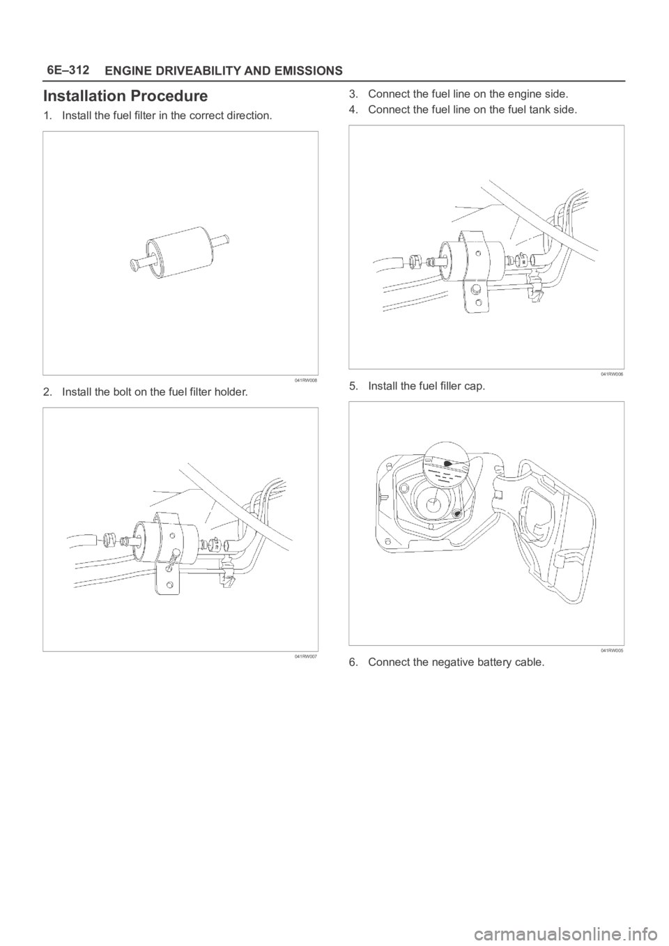
1. Install the fuel filter in the correct direction.
041RW008
2. Install the bolt on the fuel filter holder.
041RW007
3. Connect the fuel line on the engine side.
4. Connect the fuel line on the fuel tank side.
041RW006
5. Install the fuel filler cap.
041RW005
6. Connect the negative battery cable.
Page 1737 of 6000

6A – 4 ENGINE MECHANICAL
Engine Cooling
Starting System
Cooling system Coolant forced circulation
Radiator (2 tube in row) Tube type corrugated
Heat radiation capacity J/h (kcal/h) 318 x 10
6(76000)
Heat radiation area m
2(ft2) 15.63 (1.454)
Front area m
2(ft2) 0.309 (2.029)
Dry weight N (kg/lb) 83 (8.5/18.7)
Radiator cap
Valve opening pressure kPa (kg/cm
2/ psi) 93.3 – 122.7 (0.95 – 1.25/13.5 – 17.8)
Coolant capacity lit (Imp.qt./US qt.) M/T 2.5 (2.2/2.6) A/T 2.4 (2.1/2.5)
Coolant pump Centrifugal impeller type
Pulley ratio (to 1) 1.2
Coolant total capacity lit (Imp.qt./US qt.) 9.3 (8.2/9.8)
Model HITACHI S14-0
Rating
Vo l t a ge V 1 2
Output kW 2.8
Time sec 30
Number of teeth of pinion 9
Rotating direction (as viewed from pinion) Clockwise
Weight (approx.) N(kg/lb) 49 (5.0/11)
No-load characteristics
Voltage/current V/A 11/160 or less
Speed rpm 4000 or more
Load characteristics
Voltage/current V/A 8.76/300
Torque Nꞏm(kgꞏm/lbꞏft) 7.4 (0.75/5.4) or more
Speed rpm 1700 or more
Locking characteristics
Voltage/current V/A 2.5/1100 or less
Torque Nꞏm(kgꞏm/lbꞏft) 18.6 (1.9/14) or more
Page 1738 of 6000

ENGINE MECHANICAL 6A – 5
Charging System
Model (HITACHI) LR190-750B LR1100 – 731
Rated voltage V 12
Rated output A 90 100
Rotation direction
Clockwise
(As viewed from pulled)
Pulley effective diameter mm (in) 69 (2.72)
Weight N (kg/lb) 52 (5.3/11.7)
Page 1782 of 6000

ENGINE MECHANICAL 6A – 49
INSPECTION AND REPAIR
Make the necessary adjustments, repairs, and part
replacements if excessive wear or damage is
discovered during inspection.
1. Camshaft Journal diameter
1) Use a micrometer to measure each camshaft
journal diameter in two directions (1) and (2). If
the measured value is less than the specified
limit, the camshaft must be replaced.
Standard: 29.939 – 29.96 mm (1.1787 – 1.1795 in)
Limit: 29.84 mm (1.17 in)
2. Cam Height
1) Measure the cam height (H) with a micrometer.
If the measured value is less than the specified
limit, the camshaft must be replaced.
Standard: IN 46.62 mm (1.8354 in)
EX 46.72 mm (1.8394 in)
Limit: IN 46.57 mm (1.8335 in)
EX 46.67 mm (1.8374 in)3. Cam Run-Out
1) Mount the camshaft on V-blocks.
2) Measure the cam height (H) with a micrometer.
If the measured value is less than the specified
limit, the camshaft must be replaced.
Standard: 0.02 mm (0.0008 in) or less
Limit: 0.10 mm (0.0039 in)
4. Camshaft oil clearance
1) Clean the camshaft, camshaft bracket and
camshaft carrier.
2) Put camshaft carrier on the cylinder head.
3) Put camshaft on the camshaft carrier.
4) Put plastigauge on the camshaft journal.
5) Install camshaft bracket to original position and
tighten bolts to specified torque in the numerical
order shown in the illustration.
Torque: A; 22 Nꞏm (2.2 kgꞏm/15.9 lb ft)
B; 38 Nꞏm (3.9 kgꞏm/28.2 lb ft)
C; 22 Nꞏm (2.2 kgꞏm/15.9 lb ft)
D; 38 Nꞏm (3.9 kgꞏm/28.2 lb ft)
(1)Ft Rr
(2)
014RW179
H
012RW059
014RW171
CC
D
B
CC
B
CC
D
CC
B
C
A AA A A A
AAAA
110RW035
Page 1800 of 6000

ENGINE MECHANICAL 6A – 67
VALVE CLEARANCE ADJUSTMENT
NOTE:
1. Valve clearance should be inspected and adjusted
while the engine is cool.
2. The tightening of the camshaft bearing cap and
camshaft carrier assembly should be checked
before inspecting and adjusting valve clearance.
INSPECTION
1. Remove cylinder head noise insulator cover and
cylinder head cover.
Refer to “Cylinder Head” in this manual.
2. Disconnect all harness connecters of the injector
and remove harness assembly.
3. Drain oil from oil rail assembly.
4. Remove injector clamp nuts and fixing bolts to take
out injector assembly.
5. Loosen oil rail bolts, remove oil rail assembly.
6. Set cylinder No.1 to the TDC at the compression
stroke. Make sure that there is play in cylinder No.1
tappets on inlet and exhaust sides and that there is
no play in cylinder No.4 tappets.
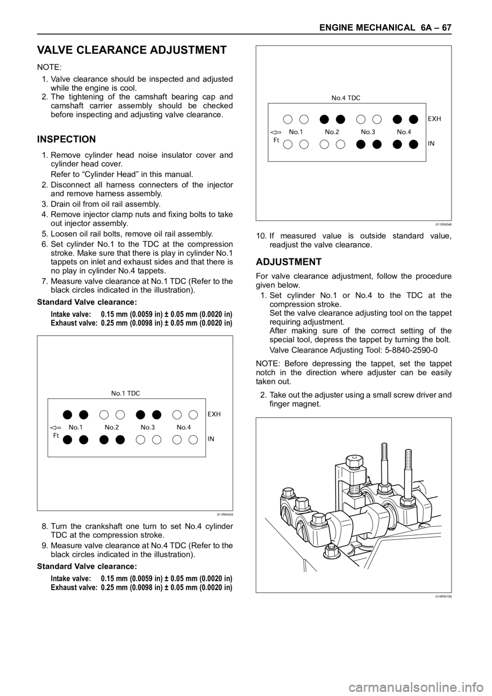
7. Measure valve clearance at No.1 TDC (Refer to the
black circles indicated in the illustration).
Standard Valve clearance:
Intake valve: 0.15 mm (0.0059 in) ± 0.05 mm (0.0020 in)
Exhaust valve: 0.25 mm (0.0098 in) ± 0.05 mm (0.0020 in)
8. Turn the crankshaft one turn to set No.4 cylinder
TDC at the compression stroke.
9. Measure valve clearance at No.4 TDC (Refer to the
black circles indicated in the illustration).
Standard Valve clearance:
Intake valve: 0.15 mm (0.0059 in) ± 0.05 mm (0.0020 in)
Exhaust valve: 0.25 mm (0.0098 in) ± 0.05 mm (0.0020 in)
10. If measured value is outside standard value,
readjust the valve clearance.
ADJUSTMENT
For valve clearance adjustment, follow the procedure
given below.
1. Set cylinder No.1 or No.4 to the TDC at the
compression stroke.
Set the valve clearance adjusting tool on the tappet
requiring adjustment.
After making sure of the correct setting of the
special tool, depress the tappet by turning the bolt.
Valve Clearance Adjusting Tool: 5-8840-2590-0
NOTE: Before depressing the tappet, set the tappet
notch in the direction where adjuster can be easily
taken out.
2. Take out the adjuster using a small screw driver and
finger magnet.
011RW045
011RW046
014RW150
Page 1820 of 6000

ENGINE MECHANICAL 6A – 87
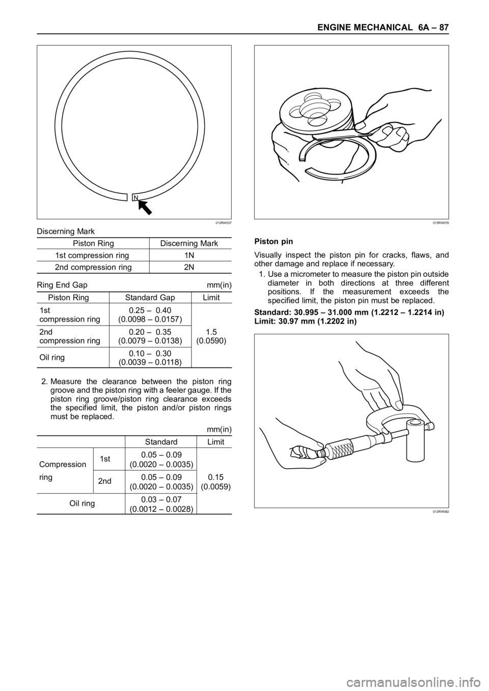
Discerning Mark
Piston Ring Discerning Mark
1st compression ring 1N
2nd compression ring 2N
Ring End Gap mm(in)
Piston Ring Standard Gap Limit
1st 0.25 – 0.40
compression ring (0.0098 – 0.0157)
2nd 0.20 – 0.35 1.5
compression ring (0.0079 – 0.0138) (0.0590)
Oil ring0.10 – 0.30
(0.0039 – 0.0118)
2. Measure the clearance between the piston ring
groove and the piston ring with a feeler gauge. If the
piston ring groove/piston ring clearance exceeds
the specified limit, the piston and/or piston rings
must be replaced.
mm(in)
Standard Limit
1st0.05 – 0.09
Compression (0.0020 – 0.0035)
ring
2nd0.05 – 0.09 0.15
(0.0020 – 0.0035) (0.0059)
Oil ring0.03 – 0.07
(0.0012 – 0.0028)Piston pin
Visually inspect the piston pin for cracks, flaws, and
other damage and replace if necessary.
1. Use a micrometer to measure the piston pin outside
diameter in both directions at three different
positions. If the measurement exceeds the
specified limit, the piston pin must be replaced.
Standard: 30.995 – 31.000 mm (1.2212 – 1.2214 in)
Limit: 30.97 mm (1.2202 in)
N
012RW037015RW076
012RW082
Page 1827 of 6000

6A – 94 ENGINE MECHANICAL
Cylinder Bore Measurement
1. Use a cylinder gauge to measure the cylinder bore
measuring direction for thrust and radial at
measuring points.
Legend
Measuring Point 1; 20 mm
2; 90 mm
3; 160 mm
2. Select the right piston grade by the averaged
cylinder bore measurement (maximum and
minimum value eliminated).
Cylinder bore diameter mm(in)
Grade mark Standard
A 95.421 – 95.430 (3.7567 – 3.7571)
B 95.431 – 95.440 (3.7571 – 3.7575)
C 95.441 – 95.450 (3.7575 – 3.7579)
3. If measured values exceed the limit, replace or
adjust the cylinder block honing or boring.
Limit 95.950 mm (3.7776 in)
4. Boring of the cylinder bore is allowed until it is
0.5 mm (0.0197 in) diameter and oversized piston
is available as a service part.
Boring Cylinder Block
1. Use an oversized piston on the basis of above
mentioned cylinder using the largest inside
diameter.
2. Measure the piston outside diameter at right angles
with piston pin at a piston grade measuring point
69.75 mm (2.7461 in) from piston top surface and
calculate a inside diameter for cylinder boring.
3. Calculation of cylinder bore boring.
D + C – H (mm)
D; Outside diameter piston (mm)
C; Clearance between Cylinder bore and piston
0.092 – 0.110 mm (0.0036 – 0.0043 in)
H; Honing allowance
Less than 0.03 mm (0.0012 in)
The oversize pistons are available three grades.
4. Honing the cylinder bore after boring.
5. Measure cylinder bore after honing.
Difference between each cylinder bore
Less than 0.02 mm (0.0008 in)
Cylinder bore and piston grade (After boring) mm(in)
GradeOversize Piston Bore
Mark
Outside Diameter Diameter
A95.820 – 95.829 95.921 – 95.930
(3.7724 – 3.7728) (3.7764 – 3.7768)
B95.830 – 95.839 95.931 – 95.940
(3.7728 – 3.7732) (3.7768 – 3.7772)
C95.840 – 95.849 95.941 – 95.950
(3.7732 – 3.7736 ) (3.7772 – 3.7776)
REASSEMBLY
1. Cylinder Block
2. Piston Cooling Oil Pipe
1) Fix the cooling jet pipes with knock pins on the
cylinder block.
2) Install the oil pipe for piston cooling in the
cylinder block, tightening a relief valve (1) and
four joint bolts (2) to the specified torque.
If oil jet pipe is forcibly assembled, the end of oil
jet may bend. It could make it impossible to
supply oil to the piston cooling hole, sometimes
causing piston seizure.
Sufficient care should be taken to pipe assembly
work.
321
012RW117