Page 1072 of 6000
6C–5
ENGINE FUEL
Installation
1. Install the fuel filter in the proper direction.
2. Install fuel filter holder fixing bolt.
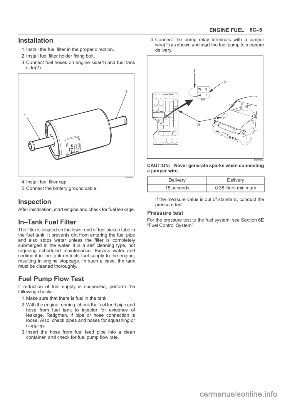
3. Connect fuel hoses on engine side(1) and fuel tank
side(2).
041RW001
4. Install fuel filler cap
5. Connect the battery ground cable.
Inspection
After installation, start engine and check for fuel leakage.
In–Tank Fuel Filter
The filter is located on the lower end of fuel pickup tube in
the fuel tank. It prevents dirt from entering the fuel pipe
and also stops water unless the filter is completely
submerged in the water. It is a self cleaning type, not
requiring scheduled maintenance. Excess water and
sediment in the tank restricts fuel supply to the engine,
resulting in engine stoppage. In such a case, the tank
must be cleaned thoroughly.
Fuel Pump Flow Test
If reduction of fuel supply is suspected, perform the
following checks:
1. Make sure that there is fuel in the tank.
2. With the engine running, check the fuel feed pipe and
hose from fuel tank to injector for evidence of
leakage. Retighten, if pipe or hose connection is
loose. Also, check pipes and hoses for squashing or
clogging.
3. Insert the hose from fuel feed pipe into a clean
container, and check for fuel pump flow rate.4. Connect the pump relay terminals with a jumper
wire(1) as shown and start the fuel pump to measure
delivery.
140RW002
CAUTION: Never generate sparks when connecting
a jumper wire.
Delivery
Delivery
15 seconds0.38 liters minimum
If the measure value is out of standard, conduct the
pressure test.
Pressure test
For the pressure test to the fuel system, see Section 6E
“Fuel Control System”.
Page 1083 of 6000
6D1–4
ENGINE ELECTRICAL
4. Attach one end of the remaining cable to the negative
terminal of the booster battery.
Attach the other end of the same cable to a solid
engine ground (such as the air conditioning
compressor bracket or the generator mounting
bracket) of the vehicle with the discharged battery.
The ground connection must be at least 450 mm (18
in.) from the battery of the vehicle whose battery is
being charged.
WARNING: NEVER ATTACH THE END OF THE
JUMPER CABLE DIRECTLY TO THE NEGATIVE
TERMINAL OF THE DEAD BATTERY.
5. Start the engine of the vehicle with the good battery.
Make sure that all unnecessary electrical accessories
have been turned “OFF”.
6. Start the engine of the vehicle with the dead battery.
7. To remove the jumper cables, follow the above
directions in reverse order.
Be sure to first disconnect the negative cable from the
vehicle with the discharged battery.
Battery Removal
061RS002
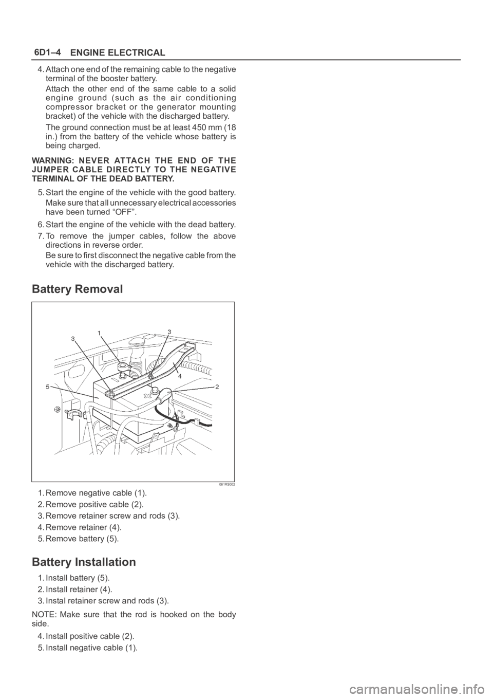
1. Remove negative cable (1).
2. Remove positive cable (2).
3. Remove retainer screw and rods (3).
4. Remove retainer (4).
5. Remove battery (5).
Battery Installation
1. Install battery (5).
2. Install retainer (4).
3. Instal retainer screw and rods (3).
NOTE: Make sure that the rod is hooked on the body
side.
4. Install positive cable (2).
5. Install negative cable (1).
Page 1103 of 6000
6D3–12STARTING AND CHARGING SYSTEM
Continuity of Contacts
With the plunger faced downward, push down the
magnetic switch. In this state, check for continuity
between terminals B and M. Replace, if there is no
continuity (i.e., contacts are faulty).
065RW018
Pinion
Check if the pinion rotates smoothly in drive direction by
hand, or if it is locked when it is rotated in reverse. If not,
replace the pinion.
065RS025
Yoke Assembly
Check a magnet inside the yoke.
Replace the yoke assembly if it is broken.
065RS026
Ball Bearing
Clamp the inner race of the ball bearing with your finger,
and check for sticking or play when rotating the outer
race.
Replace, if abnormality is found.
065RS027
Page 1104 of 6000
6D3–13 STARTING AND CHARGING SYSTEM
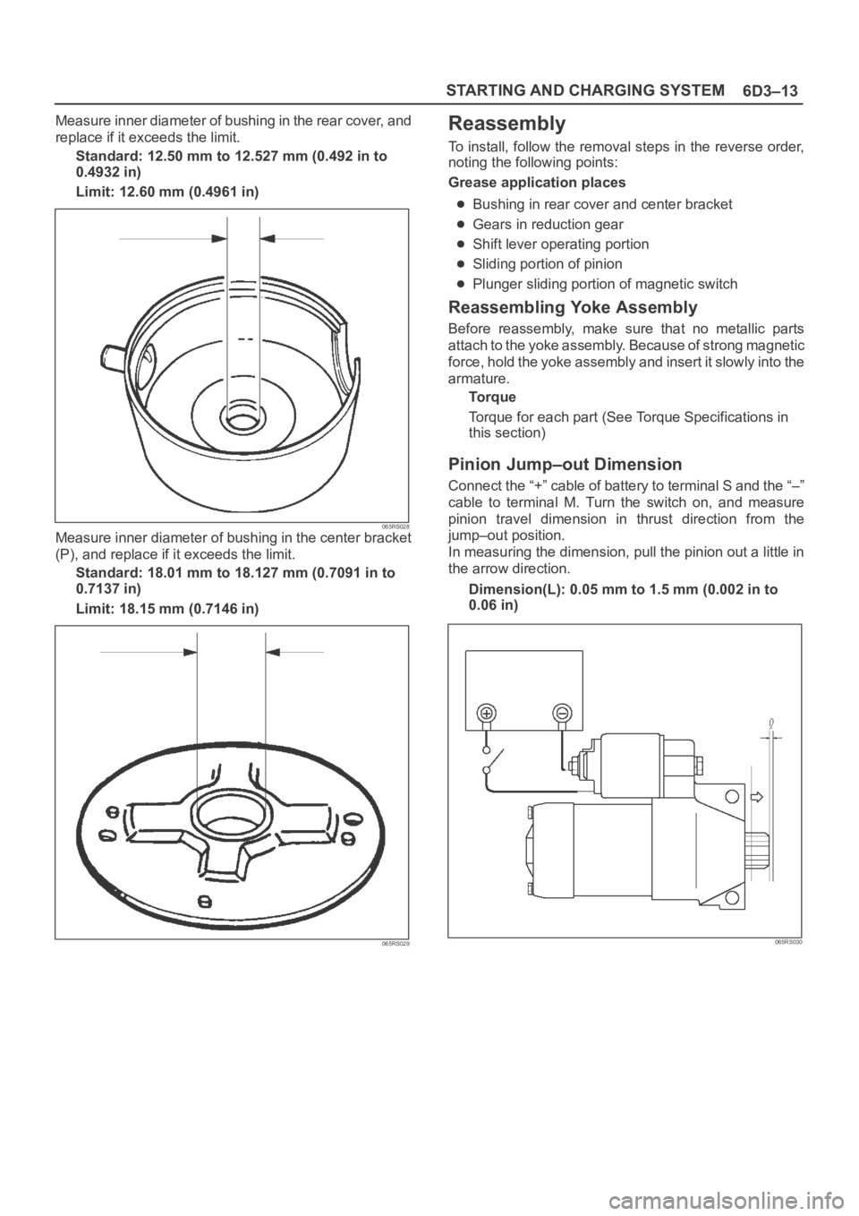
Measure inner diameter of bushing in the rear cover, and
replace if it exceeds the limit.
Standard: 12.50 mm to 12.527 mm (0.492 in to
0.4932 in)
Limit: 12.60 mm (0.4961 in)
065RS028Measure inner diameter of bushing in the center bracket
(P), and replace if it exceeds the limit.
Standard: 18.01 mm to 18.127 mm (0.7091 in to
0.7137 in)
Limit: 18.15 mm (0.7146 in)
065RS029
Reassembly
To install, follow the removal steps in the reverse order,
noting the following points:
Grease application places
Bushing in rear cover and center bracket
Gears in reduction gear
Shift lever operating portion
Sliding portion of pinion
Plunger sliding portion of magnetic switch
Reassembling Yoke Assembly
Before reassembly, make sure that no metallic parts
attach to the yoke assembly. Because of strong magnetic
force, hold the yoke assembly and insert it slowly into the
armature.
To r q u e
Torque for each part (See Torque Specifications in
this section)
Pinion Jump–out Dimension
Connect the “+” cable of battery to terminal S and the “–”
cable to terminal M. Turn the switch on, and measure
pinion travel dimension in thrust direction from the
jump–out position.
In measuring the dimension, pull the pinion out a little in
the arrow direction.
Dimension(L): 0.05 mm to 1.5 mm (0.002 in to
0.06 in)
065RS030
Page 1106 of 6000
6D3–15 STARTING AND CHARGING SYSTEM
Main Data and Specifications
General Specifications
ModelHITACHI GD002350
Rating
Voltage12 V
Output1.4 Kw
Time30 sec
Number of teeth of pinion 9
Rotating direction(as viewed from pinion)Clockwise
Weight(approx.)34 N
No load characteristics
Voltage /Current 11V/90A or less
Speed 2700rpm or more
Load characteristics
Voltage/current 8.4V/250A
Torque 7.3Nꞏm(64lbꞏin.) or more
Speed 1200rpm or more
Locking characteristics
Voltage/current 3V/750A or less
To r q u e19Nꞏm(14lbꞏin) or more
Page 1115 of 6000
6D3–24STARTING AND CHARGING SYSTEM
Stator Coil
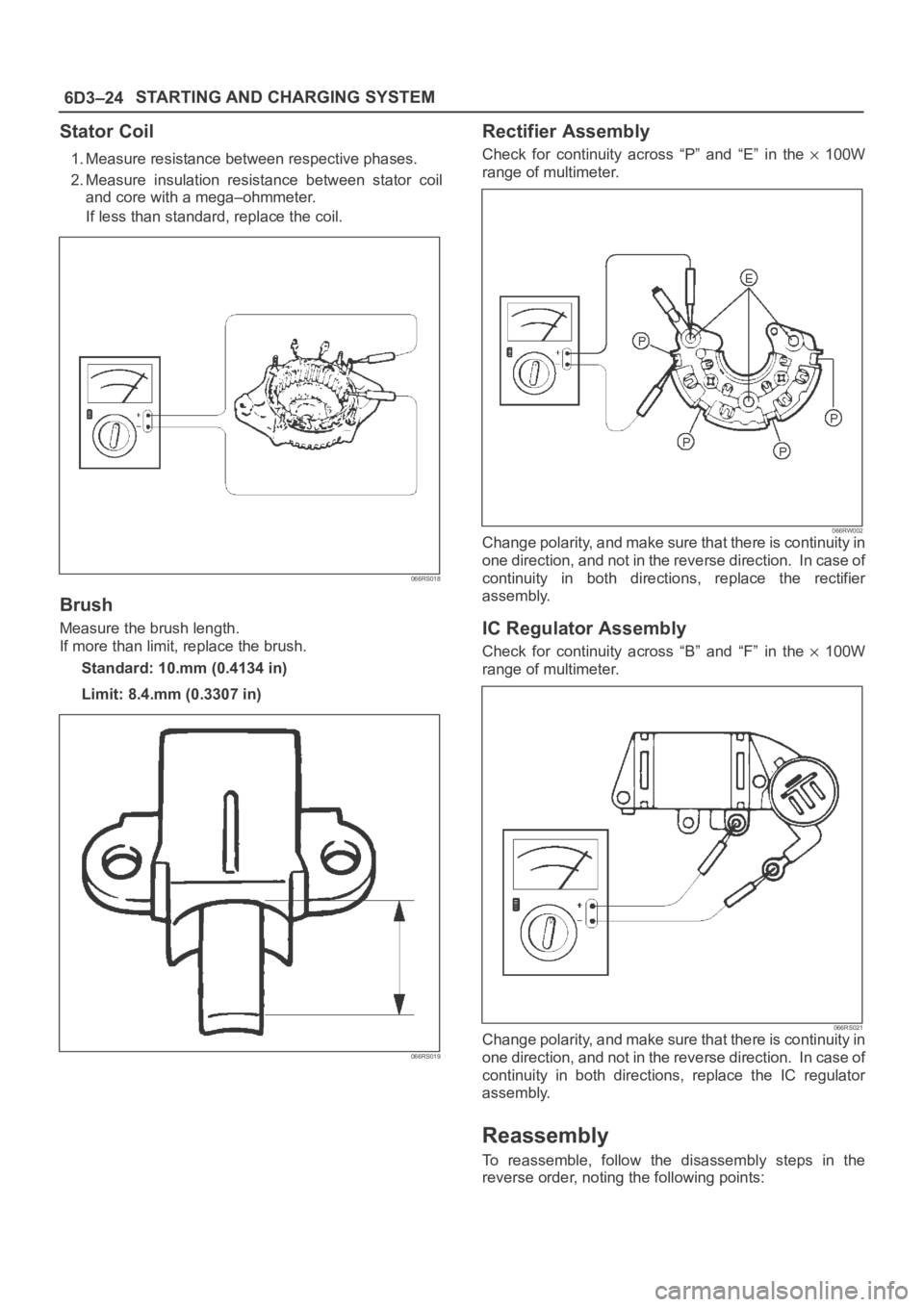
1. Measure resistance between respective phases.
2. Measure insulation resistance between stator coil
and core with a mega–ohmmeter.
If less than standard, replace the coil.
066RS018
Brush
Measure the brush length.
If more than limit, replace the brush.
Standard: 10.mm (0.4134 in)
Limit: 8.4.mm (0.3307 in)
066RS019
Rectifier Assembly
Check for continuity across “P” and “E” in the 100W
range of multimeter.
066RW002Change polarity, and make sure that there is continuity in
one direction, and not in the reverse direction. In case of
continuity in both directions, replace the rectifier
assembly.
IC Regulator Assembly
Check for continuity across “B” and “F” in the 100W
range of multimeter.
066RS021Change polarity, and make sure that there is continuity in
one direction, and not in the reverse direction. In case of
continuity in both directions, replace the IC regulator
assembly.
Reassembly
To reassemble, follow the disassembly steps in the
reverse order, noting the following points:
Page 1117 of 6000
6D3–26STARTING AND CHARGING SYSTEM
Main Data and Specifications
General Specifications
Parts Number (Nippon denso)102211—5030
ModelACHD04
Rated voltage12 V
Rated output75 A
Rotating direction (As viewed from pulley)Clockwise
Pulley effective diameter50 mm (1.97 in)
Weight44 N (33 lb)
Page 1368 of 6000
6E–251 ENGINE DRIVEABILITY AND EMISSIONS
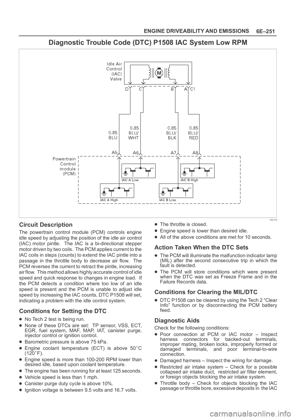
Diagnostic Trouble Code (DTC) P1508 IAC System Low RPM
T321115
Circuit Description
The powertrain control module (PCM) controls engine
idle speed by adjusting the position of the idle air control
(IAC) motor pintle. The IAC is a bi-directional stepper
motor driven by two coils. The PCM applies current to the
IAC coils in steps (counts) to extend the IAC pintle into a
passage in the throttle body to decrease air flow. The
PCM reverses the current to retract the pintle, increasing
air flow. This method allows highly accurate control of idle
speed and quick response to changes in engine load. If
the PCM detects a condition where too low of an idle
speed is present and the PCM is unable to adjust idle
speed by increasing the IAC counts, DTC P1508 will set,
indicating a problem with the idle control system.
Conditions for Setting the DTC
No Tech 2 test is being run.
None of these DTCs are set: TP sensor, VSS, ECT,
EGR, fuel system, MAF, MAP, IAT, canister purge,
injector control or ignition control.
Barometric pressure is above 75 kPa.
Engine coolant temperature (ECT) is above 50C
(120
F).
Engine speed is more than 100-200 RPM lower than
desired idle, based upon coolant temperature.
The engine has been running for at least 125 seconds.
Vehicle speed is less than 1 mph.
Canister purge duty cycle is above 10%.
Ignition voltage is between 9.5 volts and 16.7 volts.
The throttle is closed.
Engine speed is lower than desired idle.
All of the above conditions are met for 10 seconds.
Action Taken When the DTC Sets
The PCM will illuminate the malfunction indicator lamp
(MIL) after the second consecutive trip in which the
fault is detected.
The PCM will store conditions which were present
when the DTC was set as Freeze Frame and in the
Failure Records data.
Conditions for Clearing the MIL/DTC
DTC P1508 can be cleared by using the Tech 2 “Clear
Info” function or by disconnecting the PCM battery
feed.
Diagnostic Aids
Check for the following conditions:
Poor connection at PCM or IAC motor – Inspect
harness connectors for backed-out terminals,
improper mating, broken locks, improperly formed or
damaged terminals, and poor terminal-to-wire
connection.
Damaged harness – Inspect the wiring for damage.
Restricted air intake system – Check for a possible
collapsed air intake duct, restricted air filter element,
or foreign objects blocking the air intake system.
Throttle body – Check for objects blocking the IAC
passage or throttle bore, excessive deposits in the IAC