Page 692 of 6000

4C–26
DRIVE SHAFT SYSTEM
Reassembly
1. Install DOJ case to bracket.
2. Install oil seal and fix snap ring.
3. Install bearing and fix snap ring.
4. Install bracket to axle case. Tighten the bracket bolt to
the specified torque.
Torque: 116 Nꞏm (11.8 kgꞏm/85 lb ft)
5. Apply 150g of the specified grease in BJ .
6. Install dust seal .
7. Apply a thin coat of grease to the shaft for smooth
installation then install bellows.
8. Install band. Note the setting direction. After
installation, check that the bellows is free from
distortion.
412RS017
9. Install another bellows and fix band.
10. Install the ball guide with the smaller diameter side
ahead onto the shaft.
11. Install ball retainer.
12. Using snap ring pliers, install the snap ring (1)
securing the ball retainer to the shaft.
412RS013
13. Align the track on the ball (1) retainer with the window
in the cage, and install the six balls into position.
412RS018
14. Install spacer.
15. Install snap ring.
16. Enclose 150g of the specified grease in DOJ case,
then install drive shaft joint assembly. After
reassembly, move the DOJ longitudinally several
times to get to fit.
17. Install the circlip (1) so that open ends are positioned
away from the ball groove.
Page 708 of 6000

4C–42
DRIVE SHAFT SYSTEM
3. Make sure of proper position for reinstallation by
applying setting marks, then remove spider .
Inspection and Repair
Make necessary correction or parts replacement if wear,
damage, corrosion or any other abnormal condition is
found through inspection.
NOTE: When any part of the journal assembly (spider,
needle roller bearing) requires replacement, be sure to
replace the entire assembly.
Check the following parts for wear, damage, noise or any
other abnormal conditions:
1. Spider
2. Needle roller bearing
3. Yoke
4. Flange
5. Constant velocity joint
Outside Diameter of Spider Pin
Standard: 17.00 mm (0.669 in)
Limit: 16.90 mm (0.665 in)
401RS007
Propeller Shaft Run–out
Support the ends of the propeller shaft on V-blocks (2)
and check for run–out by holding the probe of a dial
indicator (1) in contact with the center part of the shaft. If
the amount of run–out is beyond the standard value for
assembly, correct with a bench press or replace the shaft
with a new propeller shaft assembly.
Standard: 0.3 mm (0.012 in)
Limit: 0.5 mm (0.02 in)
401RS027
Play in Splines in Normal Direction of
Rotation
Check the amount of play between the sleeve yoke (1)
and the propeller shaft spline (2) in the direction of
rotation, using a pointed feeler gauge.
Standard: 0.073 – 0.156 mm (0.003 – 0.006 in)
Limit: 0.3 mm (0.012 in)
401RS009
Page 718 of 6000

4C–52
DRIVE SHAFT SYSTEM
3. Make sure of proper position for reinstallation by
applying setting marks, then remove spider with
grease fitting.
Inspection and Repair
Make necessary correction or parts replacement if wear,
damage, corrosion or any other abnormal condition is
found through inspection.
NOTE: When any part of the journal assembly (spider,
needle roller bearing, grease fitting) requires
replacement, be sure to replace the entire assembly.
Check the following parts for wear, damage, noise or any
other abnormal conditions:
1. Spider
2. Needle roller bearing
3. Yoke
4. Flange
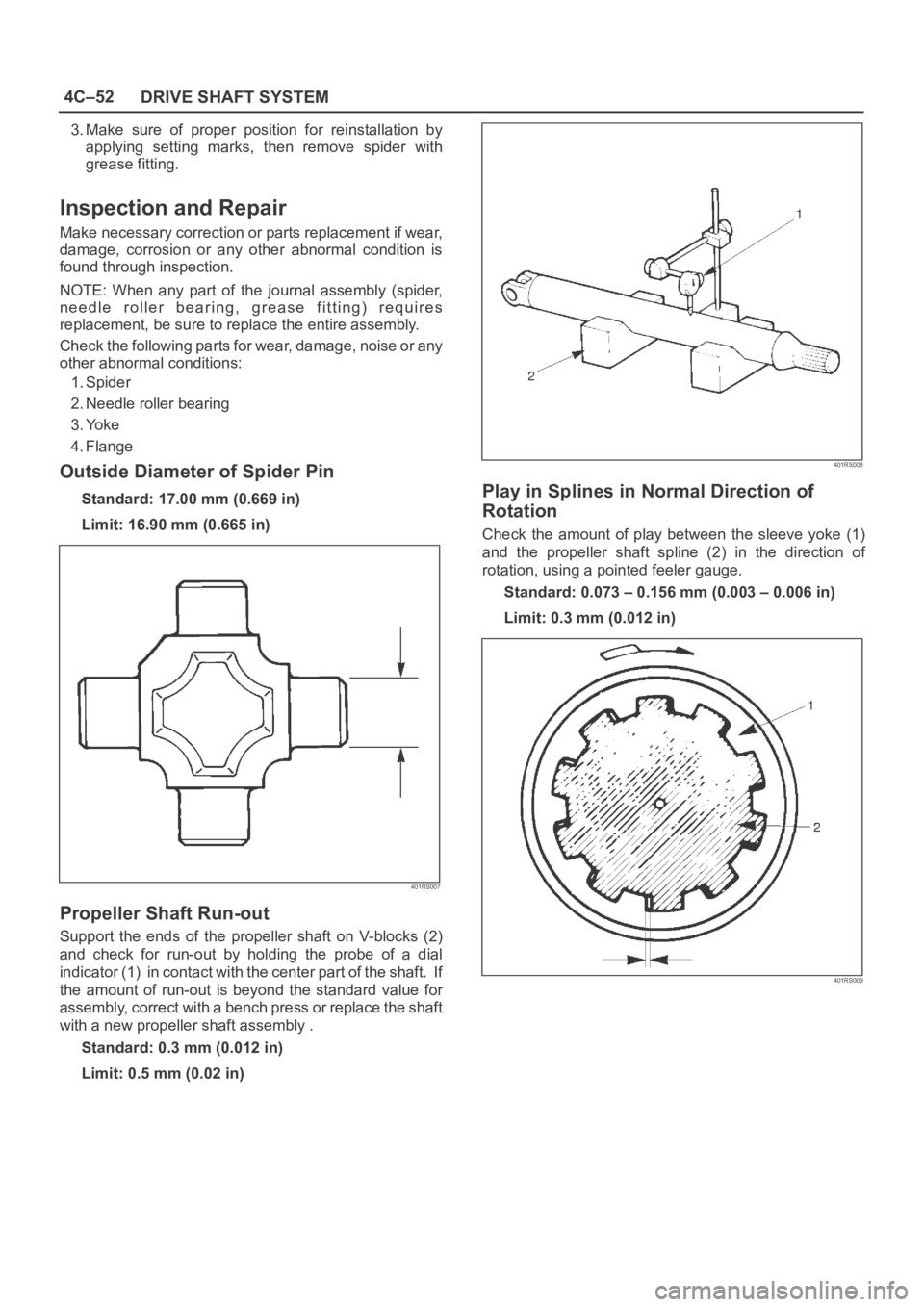
Outside Diameter of Spider Pin
Standard: 17.00 mm (0.669 in)
Limit: 16.90 mm (0.665 in)
401RS007
Propeller Shaft Run-out
Support the ends of the propeller shaft on V-blocks (2)
and check for run-out by holding the probe of a dial
indicator (1) in contact with the center part of the shaft. If
the amount of run-out is beyond the standard value for
assembly, correct with a bench press or replace the shaft
with a new propeller shaft assembly .
Standard: 0.3 mm (0.012 in)
Limit: 0.5 mm (0.02 in)
401RS008
Play in Splines in Normal Direction of
Rotation
Check the amount of play between the sleeve yoke (1)
and the propeller shaft spline (2) in the direction of
rotation, using a pointed feeler gauge.
Standard: 0.073 – 0.156 mm (0.003 – 0.006 in)
Limit: 0.3 mm (0.012 in)
401RS009
Page 749 of 6000

4D1–28
TRANSFER CASE (STANDARD TYPE)
Inspection and Repair
Refer to “TRANSFER CASE ASSEMBLY” in this section
for inspection and repair.
Reassembly
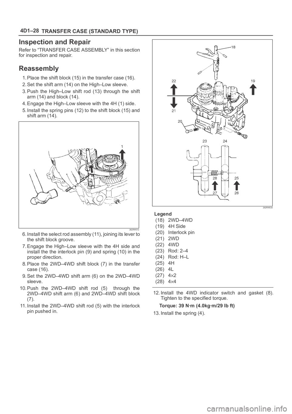
1. Place the shift block (15) in the transfer case (16).
2. Set the shift arm (14) on the High–Low sleeve.
3. Push the High–Low shift rod (13) through the shift
arm (14) and block (14).
4. Engage the High–Low sleeve with the 4H (1) side.
5. Install the spring pins (12) to the shift block (15) and
shift arm (14).
262RW012
6 . I n s t a l l t h e s e l e c t r o d a s s e m b l y ( 11 ) , j o i n i n g i t s l e v e r t o
the shift block groove.
7. Engage the High–Low sleeve with the 4H side and
install the the interlock pin (9) and spring (10) in the
proper direction.
8. Place the 2WD–4WD shift block (7) in the transfer
case (16).
9. Set the 2WD–4WD shift arm (6) on the 2WD–4WD
sleeve.
10. Push the 2WD–4WD shift rod (5) through the
2WD–4WD shift arm (6) and 2WD–4WD shift block
(7).
11. Install the 2WD–4WD shift rod (5) with the interlock
pin pushed in.
262RW035
Legend
(18) 2WD–4WD
(19) 4H Side
(20) Interlock pin
(21) 2WD
(22) 4WD
(23) Rod: 2–4
(24) Rod: H–L
(25) 4H
(26) 4L
(27) 4
2
(28) 4
4
12. Install the 4WD indicator switch and gasket (8).
Tighten to the specified torque.
Torque: 39 Nꞏm (4.0kgꞏm/29 lb ft)
13. Install the spring (4).
Page 773 of 6000
4D2–6
TRANSFER CASE (TOD)
2. Using the oil seal installer 5-8840-2412-0 (J-42804),
install the oil seal.
NOTE: When installing the oil seal, pay attention to the
direction.
261RW051
Rear Output Shaft Oil Seal
Distance between the transfer case end and oil seal.
NOTE: When installing the oil seal to the specified
dimension, be careful not to damage it.
Distance : 9.85 — 10.35mm (0.39 — 0.41 in)
A04RW004
3. Mount the rear companion flange, O-ring , washer,
and nut to the transfer case in this order.
4. Using the flange holder 5-8840-0133-0 (J-8614-11),
install a new end nut.
Torque : 167 Nꞏm (17 kgꞏm /123 lb ft)
5. Using the punch 5-8840-2293-0 (J-39209), stake the
end nut at two spots.
NOTE: Check the staked end nut is free from cracks.
266RW028
260RW007
6. Install the rear propeller shaft to the transfer case and
tighten to the specified torque.
Torque : 63 Nꞏm (6.4 kgꞏm /46 lb ft)
Page 799 of 6000
4D2–32
TRANSFER CASE (TOD)
5. Using the installer 5-8840-2416-0 (J-42809), press-fit
the ring gear.
Pay attention to the following points.
Identify the correct direction of gear.
Do not damage the gear.
Do not press-fit the ring gear slantingly.
Press-fit the ring gear to the innermost.
Remove burrs generated by press-fitting.
If the transfer case has serrations, match them with
those of the gear and press-fit the gear.
261RW054
261RW034
6. Install the snap ring to the transfer case.
7. Install the circular hub.
8. Install the snap ring to the carrier.
9. Mount the carrier assembly to the input shaft.
10. Check the direction of thrust plate and mount it to the
input shaft.
265RW008
11. Mount the ball bearing to the input shaft so that the
snap ring will be installed to the input shaft.
265RW003
12. Install the snap ring to the input shaft.
13. Install the snap ring to the transfer case.
Page 875 of 6000
5B–3 ANTI–LOCK BRAKE SYSTEM
G-Sensor
Removal
350RX001
1. Remove center console.
Refer to Consoles in Body and Accessories
section.
2. Remove clip from G-sensor connector (1), then
disconnect connector.
3. Remove G-sensor assembly fixing bolt (2).
4. Remove G-sensor assembly (3).
Inspection and Repair
Refer to Chart B-5 in Brake Control System section.
Installation
1. Install G-sensor assembly (3).
Care should be taken so that the G-sensor is not
installed in the wrong direction.
2. Install G-sensor assembly fixing bolt (2).
Tighten the fixing bolt to the specified torque.
Torque : 10 Nꞏm (1.0kgꞏm/87 lb in)
3. Install G-sensor wiring connector (1).
4. Install center console.
Refer to Consoles in Body and Accessories
section.
Page 985 of 6000

6A–29
ENGINE MECHANICAL
Timing Belt
Removal
1. Disconnect battery ground cable.
2. Remove air cleaner assembly.
3. Remove radiator upper fan shroud from radiator.
4. Move drive belt tensioner to loose side using wrench
then remove drive belt.
850RW001
Legend
(1) Crankshaft Pulley
(2) Cooling Fan Pulley
(3) Tensioner
(4) Generator
(5) Air Conditioner Compressor
(6) Power Steering Oil Pump
(7) Drive Belt
5. Remove cooling fan assembly four nuts, then the
cooling fan assembly.
6. Remove cooling fan drive pulley assembly.
7. Remove idle pulley assembly.
8. Remove serpentine belt tensioner assembly.
9. Remove power steering pump assembly.
10. Remove crankshaft pulley assembly using
5–8840–0133–0 crankshaft holder, hold crankshaft
pulley remove center bolt, then the pulley.
11. Remove right side timing belt cover then left side
timing belt cover.
12. Remove lower timing belt cover
13. Remove pusher.CAUTION: The pusher prevents air from entering
the oil chamber. Its rod must always be facing
upward.
014RW011
Legend
(1) Up Side
(2) Down Side
(3) Direction For Installation
(4) Locking Pin
14. Remove timing belt.
CAUTION:
1. Do not bend or twist the belt, otherwise its core
could be damaged. The belt should not be bent at
a radius less than 30 mm.
2. Do not allow oil or other chemical substances to
come in contact with the belt. They will shorten
the life.
3. Do not attempt to pry or stretch the belt with a
screw driver or any other tool during installation.
4. Store timing belt in a cool and dark place. Never
expose the belt direct sunlight or heat.