1998 OPEL FRONTERA side mirror
[x] Cancel search: side mirrorPage 2568 of 6000
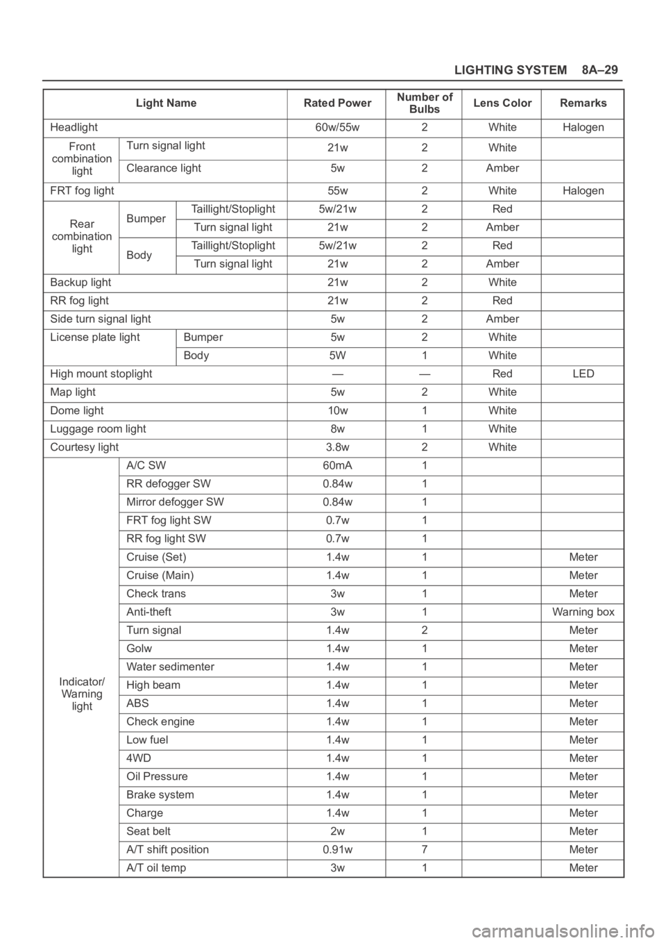
LIGHTING SYSTEM8A–29
Light NameRated PowerNumber of
BulbsLens ColorRemarks
Headlight60w/55w2WhiteHalogen
FrontTurn signal light21w2Whitecombination
lightClearance light5w2Amber
FRT fog light55w2WhiteHalogen
Taillight/Stoplight5w/21w2Red
RearBumperTurn signal light21w2Ambercombination
lightTaillight/Stoplight5w/21w2RedBodyTurn signal light21w2Amber
Backup light21w2White
RR fog light21w2Red
Side turn signal light5w2Amber
License plate lightBumper5w2White
Body5W1White
High mount stoplight——RedLED
Map light5w2White
Dome light10w1White
Luggage room light8w1White
Courtesy light3.8w2White
A/C SW60mA1
RR defogger SW0.84w1
Mirror defogger SW0.84w1
FRT fog light SW0.7w1
RR fog light SW0.7w1
Cruise (Set)1.4w1Meter
Cruise (Main)1.4w1Meter
Check trans3w1Meter
Anti-theft3w1Warning box
Turn signal1.4w2Meter
Golw1.4w1Meter
Water sedimenter1.4w1Meter
Indicator/High beam1.4w1MeterWa rnin g
lightABS1.4w1Meter
Check engine1.4w1Meter
Low fuel1.4w1Meter
4WD1.4w1Meter
Oil Pressure1.4w1Meter
Brake system1.4w1Meter
Charge1.4w1Meter
Seat belt2w1Meter
A/T shift position0.91w7Meter
A/T oil temp3w1Meter
Page 3264 of 6000
8F–69 BODY STRUCTURE
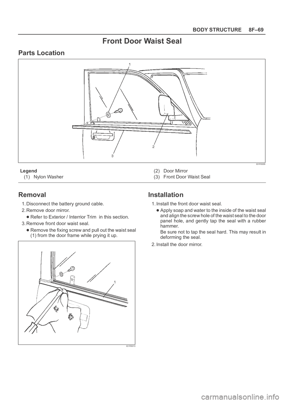
Front Door Waist Seal
Parts Location
631RS009
Legend
(1) Nylon Washer(2) Door Mirror
(3) Front Door Waist Seal
Removal
1. Disconnect the battery ground cable.
2. Remove door mirror.
Refer to Exterior / Interrior Trim in this section.
3. Remove front door waist seal.
Remove the fixing screw and pull out the waist seal
(1) from the door frame while prying it up.
631RS010
Installation
1. Install the front door waist seal.
Apply soap and water to the inside of the waist seal
and align the screw hole of the waist seal to the door
panel hole, and gently tap the seal with a rubber
hammer.
Be sure not to tap the seal hard. This may result in
deforming the seal.
2. Install the door mirror.
Page 3380 of 6000
EXTERIOR/INTERIOR TRIM8J–1
BODY AND ACCESSORIES
EXTERIOR / INTERIOR TRIM
CONTENTS
Service Precaution 8J–2. . . . . . . . . . . . . . . . . . . . . .
Dash Side Trim Panel 8J–3. . . . . . . . . . . . . . . . . . . .
Removal 8J–3. . . . . . . . . . . . . . . . . . . . . . . . . . . . .
Installation 8J–3. . . . . . . . . . . . . . . . . . . . . . . . . . . .
Assist Grip 8J–3. . . . . . . . . . . . . . . . . . . . . . . . . . . . .
Parts Location 8J–3. . . . . . . . . . . . . . . . . . . . . . . .
Removal and Installation 8J–3. . . . . . . . . . . . . . .
Consoles 8J–4. . . . . . . . . . . . . . . . . . . . . . . . . . . . . . .
Consoles and Associated Parts 8J–4. . . . . . . . .
Removal 8J–4. . . . . . . . . . . . . . . . . . . . . . . . . . . . .
Installation 8J–5. . . . . . . . . . . . . . . . . . . . . . . . . . . .
Front Door Trim Panel 8J–6. . . . . . . . . . . . . . . . . . .
Front Door Trim Panel and Associated
Parts 8J–6. . . . . . . . . . . . . . . . . . . . . . . . . . . . . . . .
Removal 8J–6. . . . . . . . . . . . . . . . . . . . . . . . . . . . .
Installation 8J–9. . . . . . . . . . . . . . . . . . . . . . . . . . . .
Rear Door Trim Panel 8J–10. . . . . . . . . . . . . . . . . . . .
Rear Door Trim Panel and Associated
Parts 8J–10. . . . . . . . . . . . . . . . . . . . . . . . . . . . . . . .
Removal 8J–10. . . . . . . . . . . . . . . . . . . . . . . . . . . . .
Installation 8J–11. . . . . . . . . . . . . . . . . . . . . . . . . . . .
Door Mirror 8J–13. . . . . . . . . . . . . . . . . . . . . . . . . . . . .
Door Mirror and Associated Parts 8J–13. . . . . . . .
Removal 8J–13. . . . . . . . . . . . . . . . . . . . . . . . . . . . .
Installation 8J–13. . . . . . . . . . . . . . . . . . . . . . . . . . . .
Luggage Side and Quarter Upper Trim Cover
(Long Wheel Base) 8J–14. . . . . . . . . . . . . . . . . . . . .
Luggage Side, Quarter Upper Trim Cover
and Associated Parts 8J–14. . . . . . . . . . . . . . . . . .
Removal 8J–14. . . . . . . . . . . . . . . . . . . . . . . . . . . . .
Installation 8J–16. . . . . . . . . . . . . . . . . . . . . . . . . . . .
Luggage Side and Quarter Upper Trim Cover
(Short Wheel Base) 8J–17. . . . . . . . . . . . . . . . . . . . .
Luggage Side, Quarter Upper Trim Cover
and Associated
Parts 8J–17. . . . . . . . . . . . . . . . . . . . . . . . . . . . . . . .
Removal 8J–17. . . . . . . . . . . . . . . . . . . . . . . . . . . . .
Installation 8J–19. . . . . . . . . . . . . . . . . . . . . . . . . . . .
Center Pillar and Roof Side Trim Cover
(Long Wheel Base) 8J–20. . . . . . . . . . . . . . . . . . . . .
Center Pillar, Roof Side Trim Cover and
Associated Parts 8J–20. . . . . . . . . . . . . . . . . . . . . .
Removal 8J–20. . . . . . . . . . . . . . . . . . . . . . . . . . . . .
Installation 8J–21. . . . . . . . . . . . . . . . . . . . . . . . . . . .
Roof Side Trim Cover (Short Wheel Base) 8J–22. . Roof Side Trim Cover and Associated
Parts 8J–22. . . . . . . . . . . . . . . . . . . . . . . . . . . . . . . .
Removal 8J–22. . . . . . . . . . . . . . . . . . . . . . . . . . . . .
Installation 8J–22. . . . . . . . . . . . . . . . . . . . . . . . . . . .
Front Pillar Trim Cover 8J–23. . . . . . . . . . . . . . . . . . .
Front Pillar Trim Cover and Associated
Parts 8J–23. . . . . . . . . . . . . . . . . . . . . . . . . . . . . . . .
Removal 8J–23
. . . . . . . . . . . . . . . . . . . . . . . . . . . . .
Installation 8J–23. . . . . . . . . . . . . . . . . . . . . . . . . . . .
Center Pillar Assist Grip 8J–24. . . . . . . . . . . . . . . . . .
Parts Location 8J–24. . . . . . . . . . . . . . . . . . . . . . . .
Removal and Installation 8J–24. . . . . . . . . . . . . . .
Assist Grip 8J–24. . . . . . . . . . . . . . . . . . . . . . . . . . . . .
Parts Location 8J–24. . . . . . . . . . . . . . . . . . . . . . . .
Removal and Installation 8J–24. . . . . . . . . . . . . . .
Fuel Filler Lid Opener Cable 8J–25. . . . . . . . . . . . . .
Fuel Filler Lid Opener Cable
and Associated Parts 8J–25. . . . . . . . . . . . . . . . . .
Removal 8J–25. . . . . . . . . . . . . . . . . . . . . . . . . . . . .
Installation 8J–26. . . . . . . . . . . . . . . . . . . . . . . . . . . .
Fuel Filler Door 8J–26. . . . . . . . . . . . . . . . . . . . . . . . .
Parts Location 8J–26. . . . . . . . . . . . . . . . . . . . . . . .
Removal 8J–26. . . . . . . . . . . . . . . . . . . . . . . . . . . . .
Installation 8J–26. . . . . . . . . . . . . . . . . . . . . . . . . . . .
Rocker Protector (Without Wheel
Opening Extension) 8J–27. . . . . . . . . . . . . . . . . . . . .
Rocker Protector (Without Wheel
Opening Extension) and Associated Parts 8J–27
Removal 8J–27. . . . . . . . . . . . . . . . . . . . . . . . . . . . .
Installation 8J–27. . . . . . . . . . . . . . . . . . . . . . . . . . . .
Wheel Opening Extension and Rocker
Protector Assembly 8J–28. . . . . . . . . . . . . . . . . . . . .
Wheel Opening Extension, Rocker Protector
Assembly and Associated Parts 8J–28. . . . . . . . .
Removal 8J–28. . . . . . . . . . . . . . . . . . . . . . . . . . . . .
Installation 8J–29. . . . . . . . . . . . . . . . . . . . . . . . . . . .
Mud Flaps (With Wheel Opening Extension) 8J–31
Mud Flaps (With Wheel Opening Extension)
and Associated Parts 8J–31. . . . . . . . . . . . . . . . . .
Removal 8J–31. . . . . . . . . . . . . . . . . . . . . . . . . . . . .
Installation 8J–31. . . . . . . . . . . . . . . . . . . . . . . . . . . .
Ventilation Assembly 8J–32. . . . . . . . . . . . . . . . . . . . .
Ventilation Assembly and Associated Parts 8J–32
Removal 8J–32. . . . . . . . . . . . . . . . . . . . . . . . . . . . .
Installation 8J–32. . . . . . . . . . . . . . . . . . . . . . . . . . . .
Page 3385 of 6000
8J–6EXTERIOR/INTERIOR TRIM
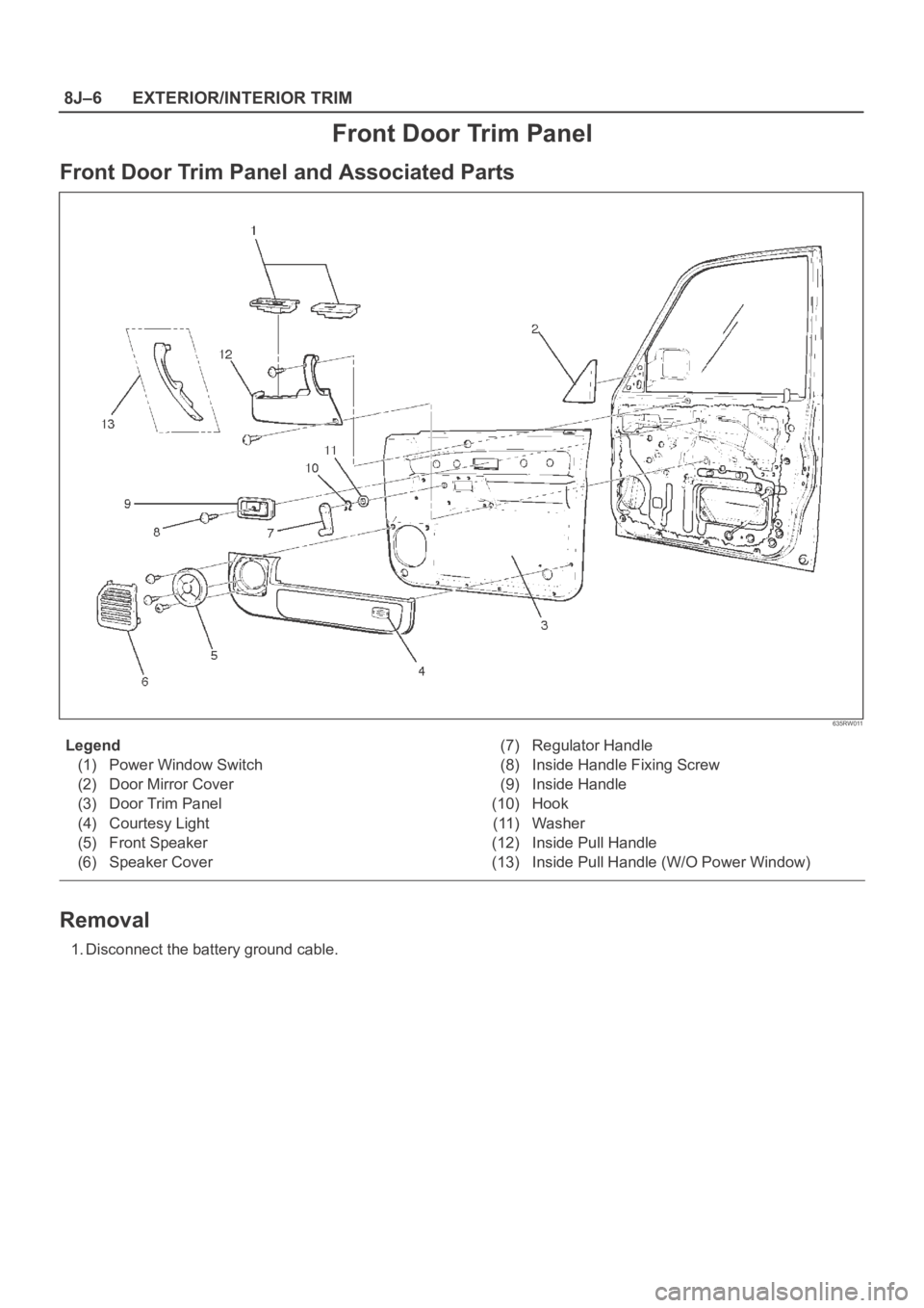
Front Door Trim Panel
Front Door Trim Panel and Associated Parts
635RW011
Legend
(1) Power Window Switch
(2) Door Mirror Cover
(3) Door Trim Panel
(4) Courtesy Light
(5) Front Speaker
(6) Speaker Cover(7) Regulator Handle
(8) Inside Handle Fixing Screw
(9) Inside Handle
(10) Hook
(11) Washer
(12) Inside Pull Handle
(13) Inside Pull Handle (W/O Power Window)
Removal
1. Disconnect the battery ground cable.
Page 3386 of 6000
EXTERIOR/INTERIOR TRIM8J–7
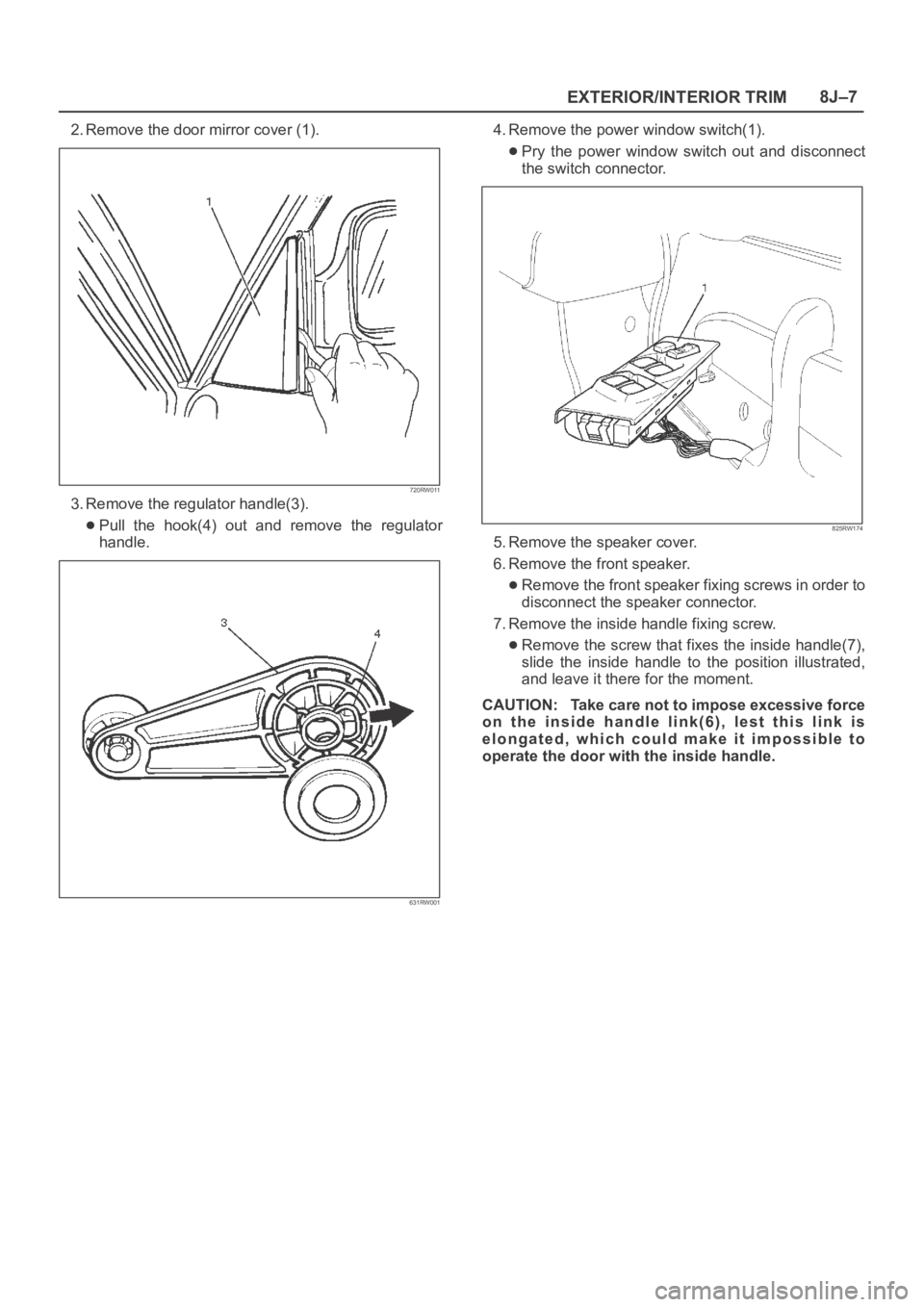
2. Remove the door mirror cover (1).
720RW011
3. Remove the regulator handle(3).
Pull the hook(4) out and remove the regulator
handle.
631RW001
4. Remove the power window switch(1).
Pry the power window switch out and disconnect
the switch connector.
825RW174
5. Remove the speaker cover.
6. Remove the front speaker.
Remove the front speaker fixing screws in order to
disconnect the speaker connector.
7. Remove the inside handle fixing screw.
Remove the screw that fixes the inside handle(7),
slide the inside handle to the position illustrated,
and leave it there for the moment.
CAUTION: Take care not to impose excessive force
on the inside handle link(6), lest this link is
elongated, which could make it impossible to
operate the door with the inside handle.
Page 3392 of 6000
EXTERIOR/INTERIOR TRIM8J–13
Door Mirror
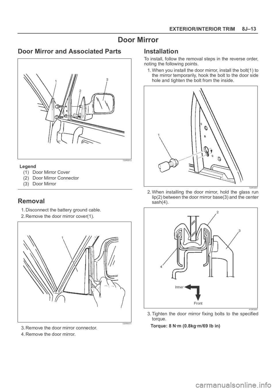
Door Mirror and Associated Parts
720RS012
Legend
(1) Door Mirror Cover
(2) Door Mirror Connector
(3) Door Mirror
Removal
1. Disconnect the battery ground cable.
2. Remove the door mirror cover(1).
720RW011
3. Remove the door mirror connector.
4. Remove the door mirror.
Installation
To install, follow the removal steps in the reverse order,
noting the following points.
1. When you install the door mirror, install the bolt(1) to
the mirror temporarily, hook the bolt to the door side
hole and tighten the bolt from the inside.
720RS001
2. When installing the door mirror, hold the glass run
lip(2) between the door mirror base(3) and the center
sash(4).
A10RS001
3. Tighten the door mirror fixing bolts to the specified
torque.
Torque: 8 Nꞏm (0.8kgꞏm/69 lb in)
Page 3417 of 6000
8J–38EXTERIOR/INTERIOR TRIM
Power Door Mirror System
General Description
The circuit consists of the starter switch, door mirror
control switch, folding switch, defogger switch and door
mirrors on both sides.
The door mirror switch consists of the control switch,
folding switch and defogger switch.
When the control switch is operated with the starter
switch at either “ACC” or “ON” position, the motors
incorporated in the door mirrors on both sides rotates to
allow the horizontal and vertical adjustment of mirror
angles.
The folding switch can be used to fold the mirror and
return it to its original position.
When turning on the door mirror defogger switch with the
starter switch at “ON” position, built-in heater in the mirror
is activated to perform the defogger function.
Door Mirror Switch Assembly (Con-
trol Switch, Folding Switch and De-
fogger Switch) Removal
1. Disconnect the battery ground cable.
2. Remove the front console assembly(2).
Remove four screws.
Remove the transmission shift lever knob.
Remove the transfer shift lever knob.
Disconnect the seat heater switch connectors (if so
equipped).
Disconnect the door mirror switch connectors.
Disconnect the power & winter switch connectors.
(A/T only)
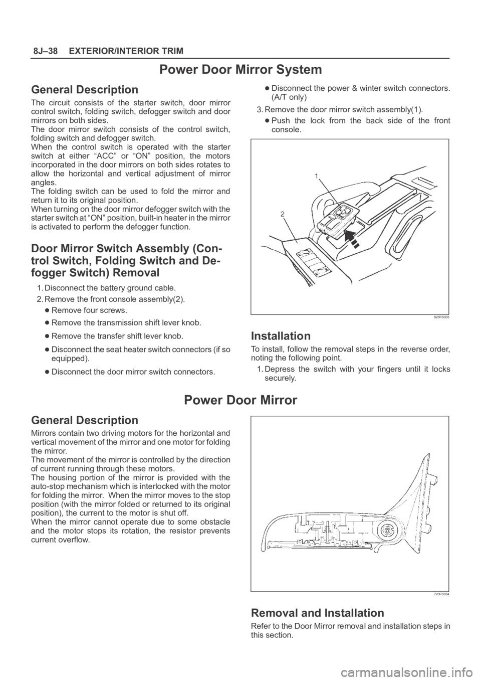
3. Remove the door mirror switch assembly(1).
Push the lock from the back side of the front
console.
825RS005
Installation
To install, follow the removal steps in the reverse order,
noting the following point.
1. Depress the switch with your fingers until it locks
securely.
Power Door Mirror
General Description
Mirrors contain two driving motors for the horizontal and
vertical movement of the mirror and one motor for folding
the mirror.
The movement of the mirror is controlled by the direction
of current running through these motors.
The housing portion of the mirror is provided with the
auto-stop mechanism which is interlocked with the motor
for folding the mirror. When the mirror moves to the stop
position (with the mirror folded or returned to its original
position), the current to the motor is shut off.
When the mirror cannot operate due to some obstacle
and the motor stops its rotation, the resistor prevents
current overflow.
720RS004
Removal and Installation
Refer to the Door Mirror removal and installation steps in
this section.