Page 1009 of 6000

6A–53
ENGINE MECHANICAL
2. Remove camshaft bracket fixing bolt (5), camshaft
bracket (6), then camshaft exhaust (7), and intake
side (8).
3. Remove tappet with shim (11).
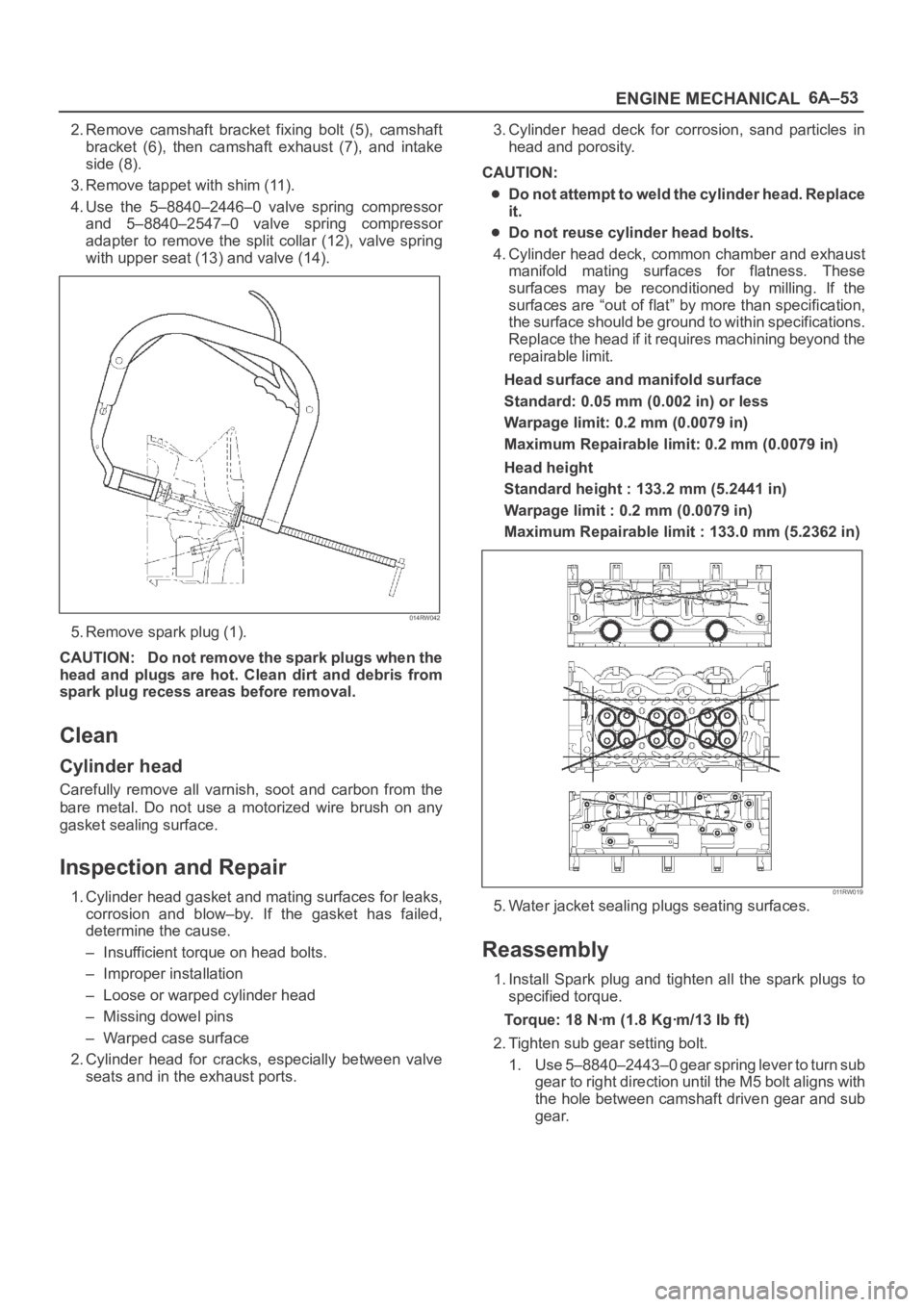
4. Use the 5–8840–2446–0 valve spring compressor
and 5–8840–2547–0 valve spring compressor
adapter to remove the split collar (12), valve spring
with upper seat (13) and valve (14).
014RW042
5. Remove spark plug (1).
CAUTION: Do not remove the spark plugs when the
head and plugs are hot. Clean dirt and debris from
spark plug recess areas before removal.
Clean
Cylinder head
Carefully remove all varnish, soot and carbon from the
bare metal. Do not use a motorized wire brush on any
gasket sealing surface.
Inspection and Repair
1. Cylinder head gasket and mating surfaces for leaks,
corrosion and blow–by. If the gasket has failed,
determine the cause.
– Insufficient torque on head bolts.
– Improper installation
– Loose or warped cylinder head
– Missing dowel pins
– Warped case surface
2. Cylinder head for cracks, especially between valve
seats and in the exhaust ports.3. Cylinder head deck for corrosion, sand particles in
head and porosity.
CAUTION:
Do not attempt to weld the cylinder head. Replace
it.
Do not reuse cylinder head bolts.
4. Cylinder head deck, common chamber and exhaust
manifold mating surfaces for flatness. These
surfaces may be reconditioned by milling. If the
surfaces are “out of flat” by more than specification,
the surface should be ground to within specifications.
Replace the head if it requires machining beyond the
repairable limit.
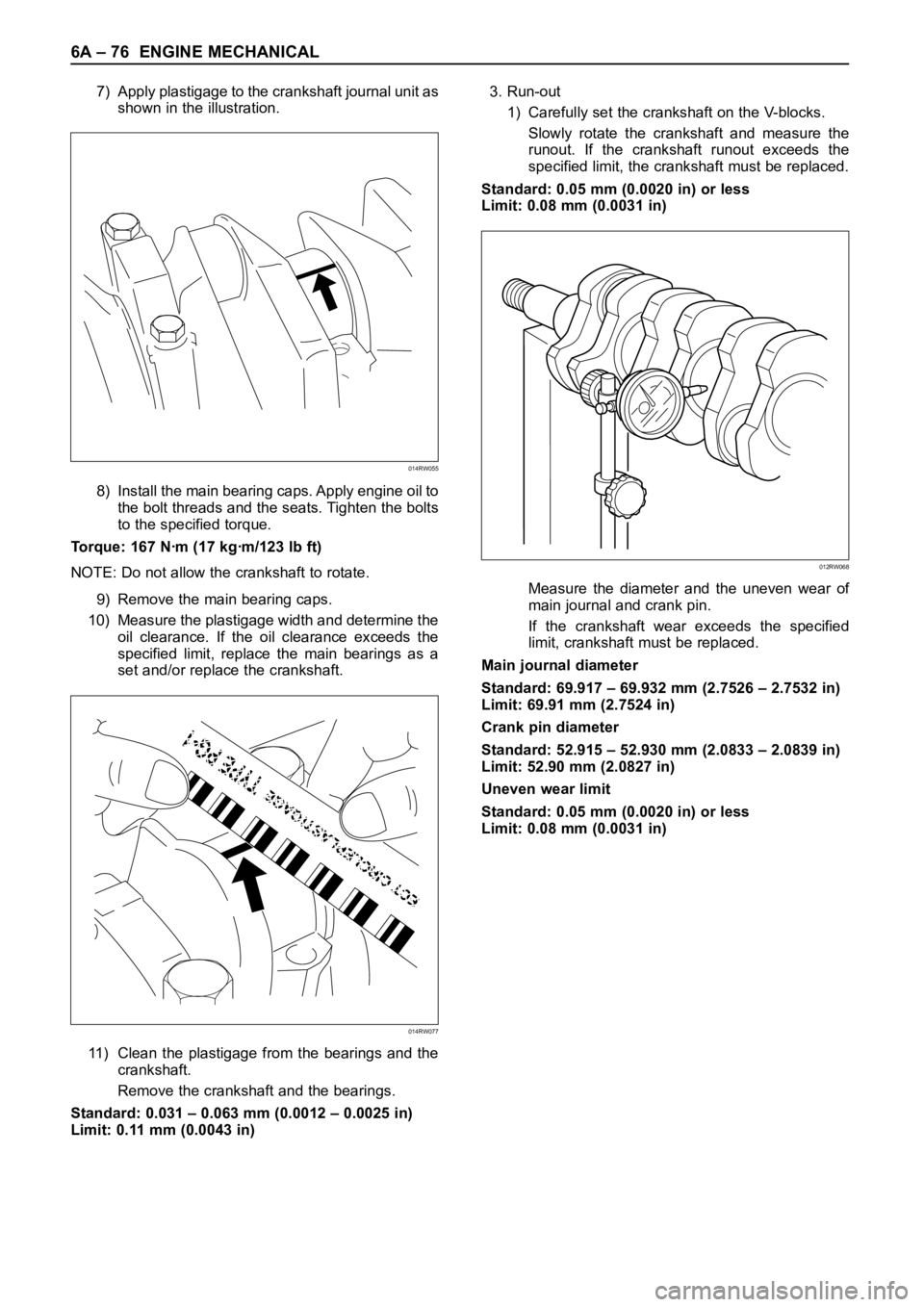
Head surface and manifold surface
Standard: 0.05 mm (0.002 in) or less
Warpage limit: 0.2 mm (0.0079 in)
Maximum Repairable limit: 0.2 mm (0.0079 in)
Head height
Standard height : 133.2 mm (5.2441 in)
Warpage limit : 0.2 mm (0.0079 in)
Maximum Repairable limit : 133.0 mm (5.2362 in)
011RW019
5. Water jacket sealing plugs seating surfaces.
Reassembly
1. Install Spark plug and tighten all the spark plugs to
specified torque.
Torque: 18 Nꞏm (1.8 Kgꞏm/13 lb ft)
2. Tighten sub gear setting bolt.
1. Use 5–8840–2443–0 gear spring lever to turn sub
gear to right direction until the M5 bolt aligns with
the hole between camshaft driven gear and sub
gear.
Page 1809 of 6000

6A – 76 ENGINE MECHANICAL
7) Apply plastigage to the crankshaft journal unit as
shown in the illustration.
8) Install the main bearing caps. Apply engine oil to
the bolt threads and the seats. Tighten the bolts
to the specified torque.
Torque: 167 Nꞏm (17 kgꞏm/123 lb ft)
NOTE: Do not allow the crankshaft to rotate.
9) Remove the main bearing caps.
10) Measure the plastigage width and determine the
oil clearance. If the oil clearance exceeds the
specified limit, replace the main bearings as a
set and/or replace the crankshaft.
11) Clean the plastigage from the bearings and the
crankshaft.
Remove the crankshaft and the bearings.
Standard: 0.031 – 0.063 mm (0.0012 – 0.0025 in)
Limit: 0.11 mm (0.0043 in)3. Run-out
1) Carefully set the crankshaft on the V-blocks.
Slowly rotate the crankshaft and measure the
runout. If the crankshaft runout exceeds the
specified limit, the crankshaft must be replaced.
Standard: 0.05 mm (0.0020 in) or less
Limit: 0.08 mm (0.0031 in)
Measure the diameter and the uneven wear of
main journal and crank pin.
If the crankshaft wear exceeds the specified
limit, crankshaft must be replaced.
Main journal diameter
Standard: 69.917 – 69.932 mm (2.7526 – 2.7532 in)
Limit: 69.91 mm (2.7524 in)
Crank pin diameter
Standard: 52.915 – 52.930 mm (2.0833 – 2.0839 in)
Limit: 52.90 mm (2.0827 in)
Uneven wear limit
Standard: 0.05 mm (0.0020 in) or less
Limit: 0.08 mm (0.0031 in)
014RW055
014RW077
012RW068
Page 3314 of 6000
8G–2SEATS
Front Seat Assembly
Front Seat Assembly and Associated Parts
750RX016
Legend
(1) Rear Cover
(2) Front Seat Assembly
(3) Seat Belt Warning Connector/Pretensioner
Harness Connector
(4) Rear Seat Foot Rest (LꞏWꞏB)(5) Seat Rail Cover (SꞏWꞏB)
(6) Door Sill Plate
(7) Riser Cover (LꞏWꞏB)
(8) Seat Slide Cover (SꞏWꞏB)
(9) Front Cover
(10) Seat Rail Cover and Hole Cover (SꞏWꞏB)
Removal
1. Disconnect the battery ground cable.
2. Remove the front cover.
3. Remove the rear cover.
Remove the cover fixing screw from the rear inner
cover, if this model is equipped with the power
seats.
4. Remove the door sill plate.5. Remove the rear seat foot rest.
Refer to the Rear Seat Foot Rest in this section.
6. Remove the riser cover.
7. Remove the seat belt warning connector (Driver’s
side only) or pretensioner harness connector.
8. Remove the front seat assembly.
Disconnect the power seat connector, if this model
is equipped with the power seats.
Page 3316 of 6000
8G–4SEATS
Disassembly
1. Remove the head rest.
2. Remove the reclining knob.
3. Remove the dial(1) (W/height adjuster).
Remove the side cover fixing screws and the dial
lock spring(2).
750RW025
4. Remove the side cover.
5. Remove the armrest assembly.
Open the armrest fastener and remove the armrest
fixing bolt.
750RS004
6. Remove the trim cover.
7. Remove the pad and frame assembly.
8. Remove the hinge cover.
9. Remove the back board assembly(3).
Pull out the back board while prying the clip (4) of
the back board free from the seat back assembly.
750RW032
10. Remove the reclining device.
Turn up the seat back trim cover in order to remove
the reclining device fixing bolts.
750RS006
Page 3317 of 6000

SEATS8G–5
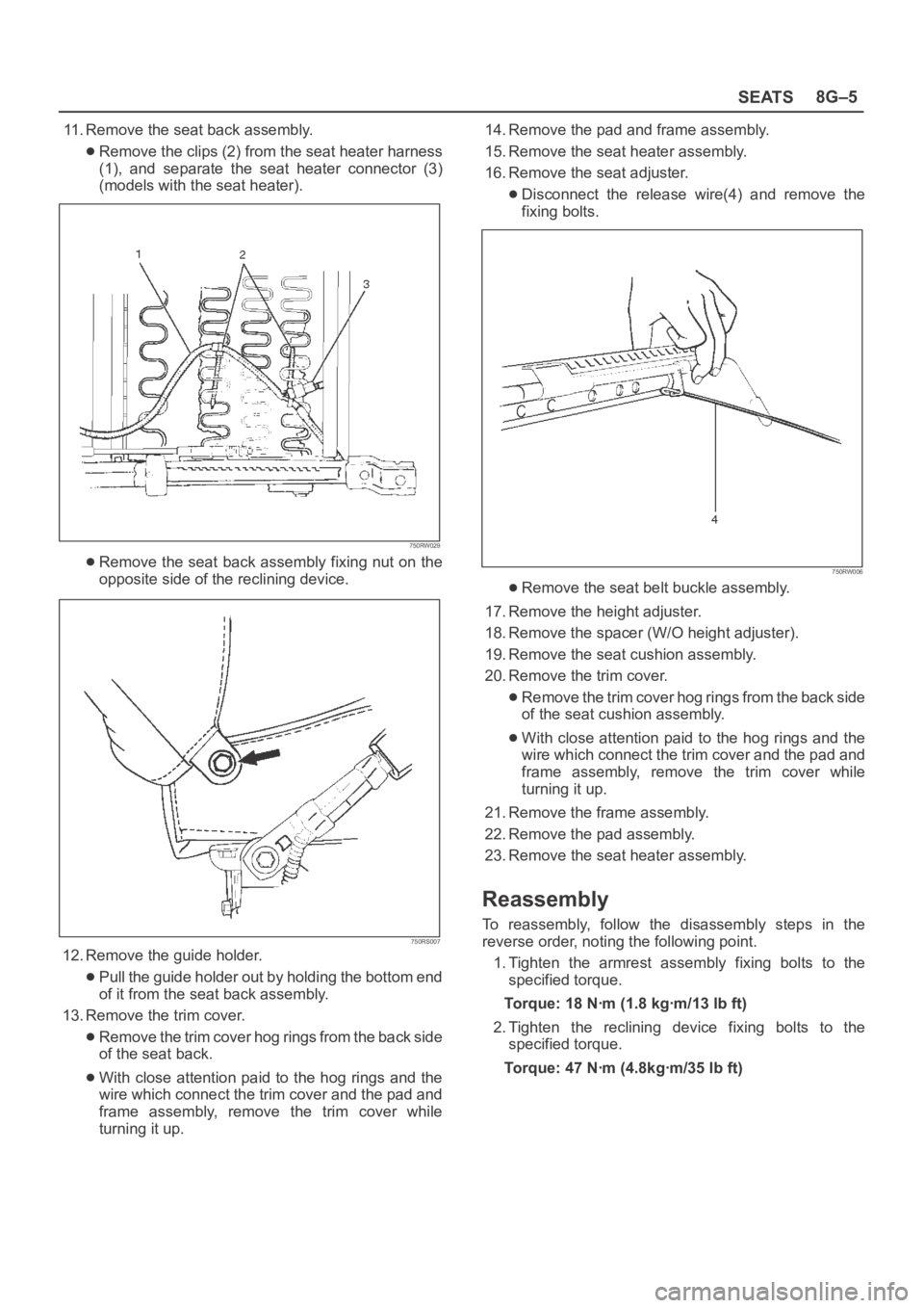
11. Remove the seat back assembly.
Remove the clips (2) from the seat heater harness
(1), and separate the seat heater connector (3)
(models with the seat heater).
750RW029
Remove the seat back assembly fixing nut on the
opposite side of the reclining device.
750RS007
12. Remove the guide holder.
Pull the guide holder out by holding the bottom end
of it from the seat back assembly.
13. Remove the trim cover.
Remove the trim cover hog rings from the back side
of the seat back.
With close attention paid to the hog rings and the
wire which connect the trim cover and the pad and
frame assembly, remove the trim cover while
turning it up.14. Remove the pad and frame assembly.
15. Remove the seat heater assembly.
16. Remove the seat adjuster.
Disconnect the release wire(4) and remove the
fixing bolts.
750RW006
Remove the seat belt buckle assembly.
17. Remove the height adjuster.
18. Remove the spacer (W/O height adjuster).
19. Remove the seat cushion assembly.
20. Remove the trim cover.
Remove the trim cover hog rings from the back side
of the seat cushion assembly.
With close attention paid to the hog rings and the
wire which connect the trim cover and the pad and
frame assembly, remove the trim cover while
turning it up.
21. Remove the frame assembly.
22. Remove the pad assembly.
23. Remove the seat heater assembly.
Reassembly
To reassembly, follow the disassembly steps in the
reverse order, noting the following point.
1. Tighten the armrest assembly fixing bolts to the
specified torque.
Torque: 18 Nꞏm (1.8 kgꞏm/13 lb ft)
2. Tighten the reclining device fixing bolts to the
specified torque.
Torque: 47 Nꞏm (4.8kgꞏm/35 lb ft)
Page 3318 of 6000
8G–6SEATS
Disassembled View (Short Wheel Base)
750RX018
Legend
(1) Head Rest
(2) Seat Back Assembly
(3) Back Board Assembly
(4) Pad & Frame Assembly
(5) Trim Cover
(6) Guide Holder
(7) Reclining Device
(8) Slide Cover
(9) Reclining Knob
(10) Frame Assembly(11) Pad Assembly
(12) Trim Cover
(13) Walk–in Cover
(14) Walk–in Assembly
(15) Seat Adjuster/Seat Adjuster (W/Pretensioner)
(16) Release Wire
(17) Seat Belt Buckle Assembly
(18) Spacer
(19) Seat Cushion Assembly
(20) Hinge Cover
Disassembly
1. Remove the head rest.
2. Remove the reclining knob.
3. Remove the side cover.
4. Remove the hinge cover.5. Remove the back board assembly.Pull out the back board while prying the clip of the
back board free from the seat back assembly.
Page 3319 of 6000
SEATS8G–7
6. Remove the reclining device.
Trun up the seat back trim cover in order to remove
the reclining device fixing bolts.
750RS006
Remove the push nut (2) and disconnect walk-in
cable (3) from reclining device (1).
750RW034
7. Remove the seat back assembly.
Remove the seat back assembly fixing nut on the
opposite side of the reclining device.
750RS007
8. Remove the guide holder.
Pull the guide holder out by holding the bottom end
of it from the seat back assembly.
9. Remove the trim cover.
Remove the trim cover hog rings from the back side
of the seat back.
With close attention paid to the hog rings and the
wire which connect the trim cover and the pad and
frame assembly, remove the trim cover while
turning it up.
10. Remove the pad and frame assembly.
11. Remove the walk-in cover.
12. Remove the seat adjuster.
Disconnect the release wire (4) and remove the
fixing bolts.
750RW006
Remove the seat belt buckle assembly.
Page 3320 of 6000
8G–8SEATS
13. Remove the walk-in assembly (passenger side).
14. Remove the spacer (driver side).
15. Remove the seat cushion assembly.
16. Remove the trim cover.
Remove the trim cover hog rings from the back side
of the seat cushion assembly.
With close attention paid to the hog rings and the
wire which connect the trim cover and the pad and
frame assembly, remove the trim cover while
turning it up.
17. Remove the frame assembly.
18. Remove the pad assembly.
Reassembly
To reassembly, follow the disassembly steps in the
reverse order, noting the following point.
1. Tighten the armrest assembly fixing bolts to the
specified torque.
Torque: 18 Nꞏm (1.8 kgꞏm/13 lb ft)
2. Tighten the reclining device fixing bolts to the
specified torque.
Torque: 47 Nꞏm (4.8kgꞏm/35 lb ft)