1998 OPEL FRONTERA remove seats
[x] Cancel search: remove seatsPage 3335 of 6000
SEATS8G–23
Reassembly (Bench Type)
To reassemble, follow the disassembly steps in the
reverse order, noting the following point.
1. Tighten the reclining device fixing bolts to the
specified torque.
Torque: 27 Nꞏm (2.8kgꞏm/20 lb ft)
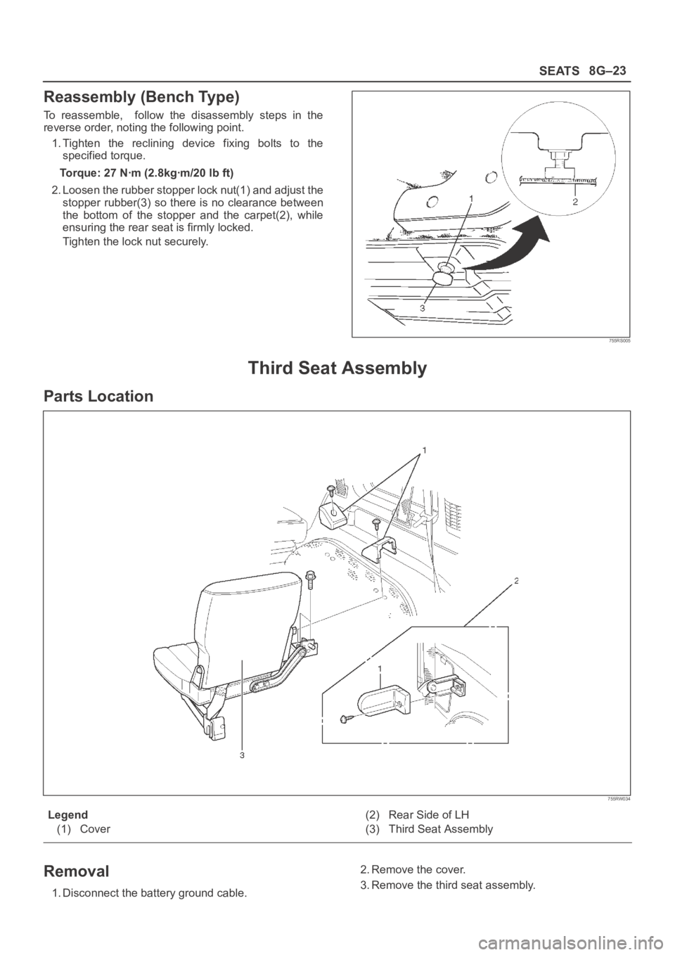
2. Loosen the rubber stopper lock nut(1) and adjust the
stopper rubber(3) so there is no clearance between
the bottom of the stopper and the carpet(2), while
ensuring the rear seat is firmly locked.
Tighten the lock nut securely.
755RS005
Third Seat Assembly
Parts Location
755RW034
Legend
(1) Cover(2) Rear Side of LH
(3) Third Seat Assembly
Removal
1. Disconnect the battery ground cable.2. Remove the cover.
3. Remove the third seat assembly.
Page 3337 of 6000
SEATS8G–25
Disassembly
1. Remove the hinge knob.
Pull the knob out from hinge assembly.
2. Remove the hinge cover.
3. Remove the hinge assembly.
4. Remove the free hinge bolt.
5. Remove the seat back assembly.
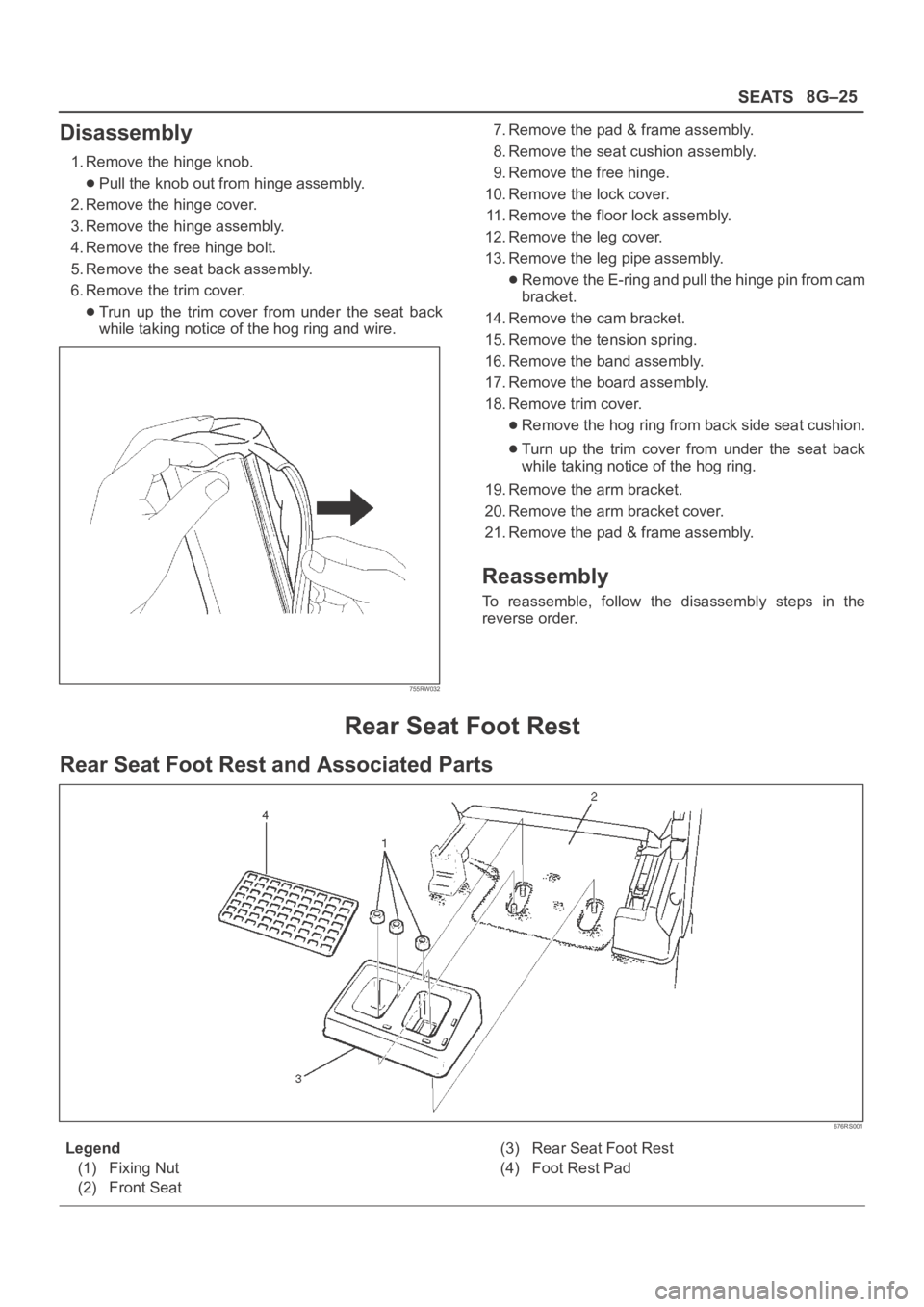
6. Remove the trim cover.
Trun up the trim cover from under the seat back
while taking notice of the hog ring and wire.
755RW032
7. Remove the pad & frame assembly.
8. Remove the seat cushion assembly.
9. Remove the free hinge.
10. Remove the lock cover.
11. Remove the floor lock assembly.
12. Remove the leg cover.
13. Remove the leg pipe assembly.
Remove the E-ring and pull the hinge pin from cam
bracket.
14. Remove the cam bracket.
15. Remove the tension spring.
16. Remove the band assembly.
17. Remove the board assembly.
18. Remove trim cover.
Remove the hog ring from back side seat cushion.
Turn up the trim cover from under the seat back
while taking notice of the hog ring.
19. Remove the arm bracket.
20. Remove the arm bracket cover.
21. Remove the pad & frame assembly.
Reassembly
To reassemble, follow the disassembly steps in the
reverse order.
Rear Seat Foot Rest
Rear Seat Foot Rest and Associated Parts
676RS001
Legend
(1) Fixing Nut
(2) Front Seat(3) Rear Seat Foot Rest
(4) Foot Rest Pad
Page 3338 of 6000
8G–26SEATS
Removal
1. Remove the foot rest pad.
676RS002
2. Remove the fixing nuts.
3. Remove the rear seat foot rest.
Installation
To install, follow the removal steps in the reverse order.
Main Data and Specifications
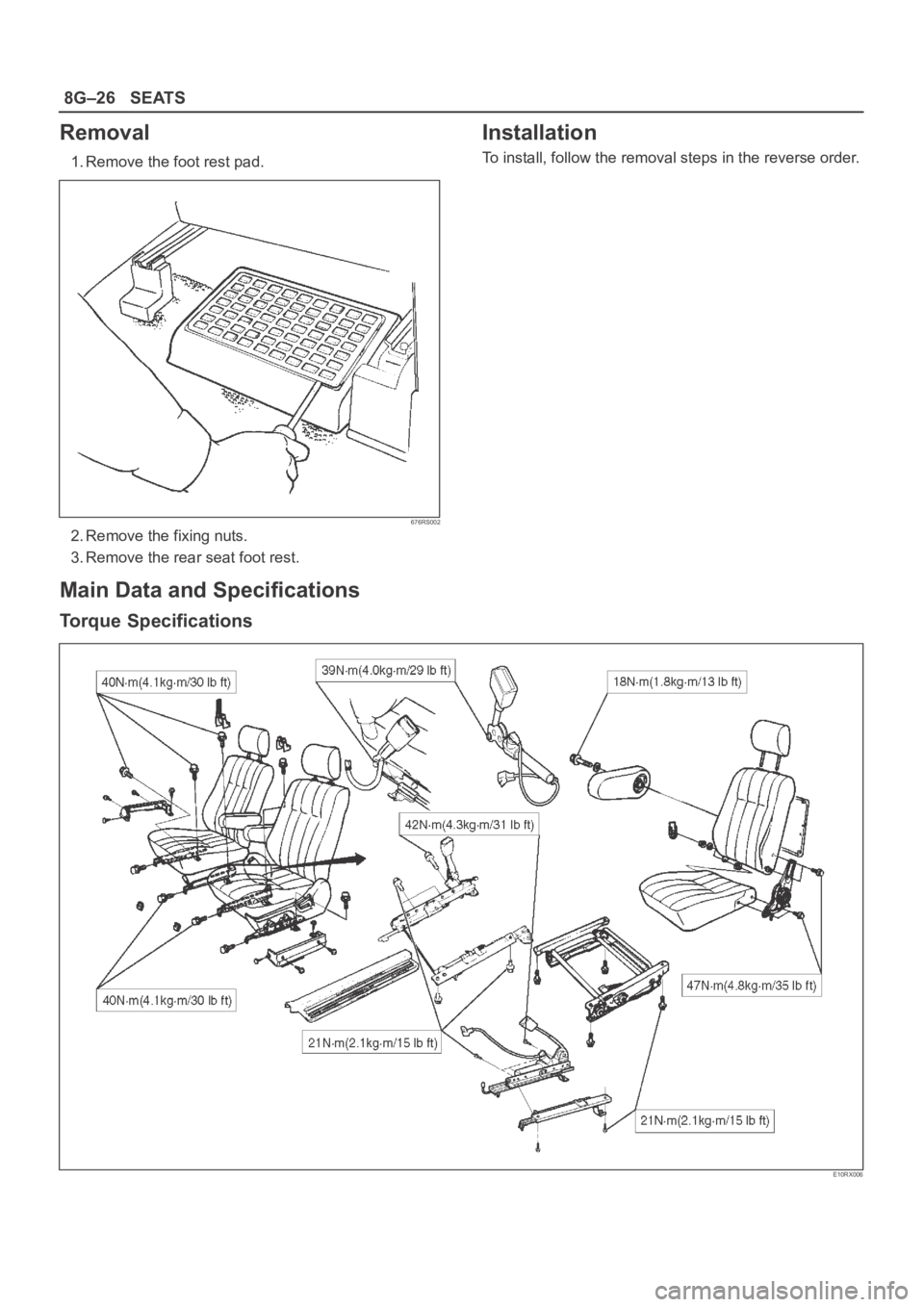
Torque Specifications
E10RX006
Page 3383 of 6000
8J–4EXTERIOR/INTERIOR TRIM
Consoles
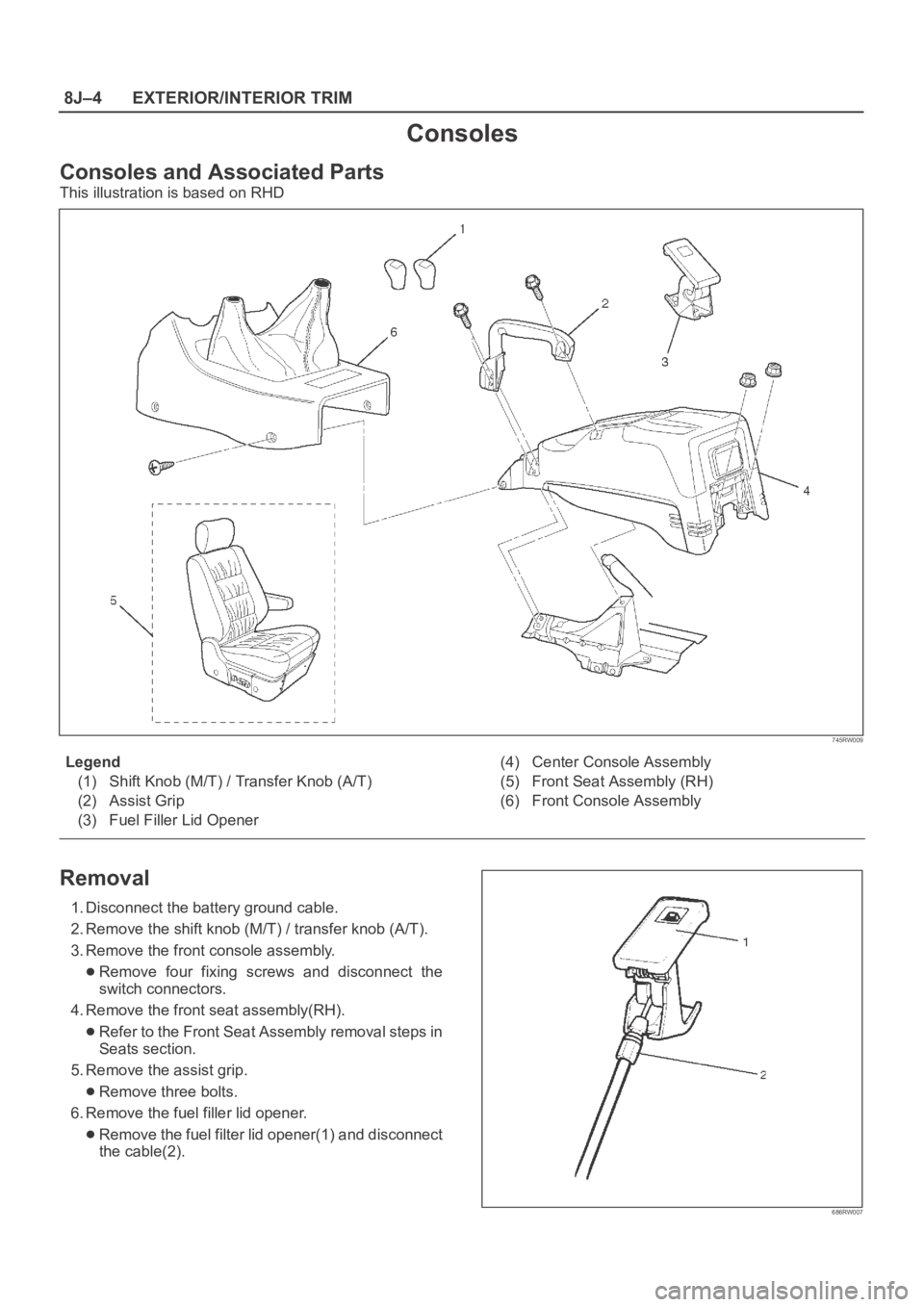
Consoles and Associated Parts
This illustration is based on RHD
745RW009
Legend
(1) Shift Knob (M/T) / Transfer Knob (A/T)
(2) Assist Grip
(3) Fuel Filler Lid Opener(4) Center Console Assembly
(5) Front Seat Assembly (RH)
(6) Front Console Assembly
Removal
1. Disconnect the battery ground cable.
2. Remove the shift knob (M/T) / transfer knob (A/T).
3. Remove the front console assembly.
Remove four fixing screws and disconnect the
switch connectors.
4. Remove the front seat assembly(RH).
Refer to the Front Seat Assembly removal steps in
Seats section.
5. Remove the assist grip.
Remove three bolts.
6. Remove the fuel filler lid opener.
Remove the fuel filter lid opener(1) and disconnect
the cable(2).
686RW007
Page 3457 of 6000
SUPPLEMENTAL RESTRAINT SYSTEM 9J–20
13. Wash your hands with mild soap and water afterward.
NOTE: The remaining steps are to be followed in the
unlikely event that the air bag assembly did not deploy
after following the above procedures.
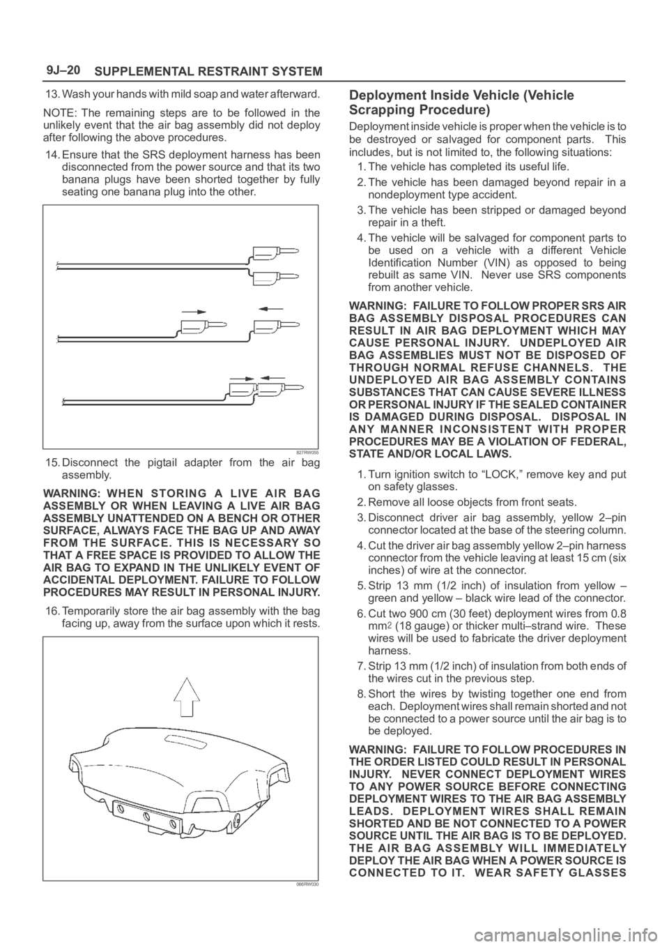
14. Ensure that the SRS deployment harness has been
disconnected from the power source and that its two
banana plugs have been shorted together by fully
seating one banana plug into the other.
827RW055
15. Disconnect the pigtail adapter from the air bag
assembly.
WARNING: WHEN STORING A LIVE AIR BAG
ASSEMBLY OR WHEN LEAVING A LIVE AIR BAG
ASSEMBLY UNATTENDED ON A BENCH OR OTHER
SURFACE, ALWAYS FACE THE BAG UP AND AWAY
FROM THE SURFACE. THIS IS NECESSARY SO
THAT A FREE SPACE IS PROVIDED TO ALLOW THE
AIR BAG TO EXPAND IN THE UNLIKELY EVENT OF
ACCIDENTAL DEPLOYMENT. FAILURE TO FOLLOW
PROCEDURES MAY RESULT IN PERSONAL INJURY.
16. Temporarily store the air bag assembly with the bag
facing up, away from the surface upon which it rests.
066RW030
Deployment Inside Vehicle (Vehicle
Scrapping Procedure)
Deployment inside vehicle is proper when the vehicle is to
be destroyed or salvaged for component parts. This
includes, but is not limited to, the following situations:
1. The vehicle has completed its useful life.
2. The vehicle has been damaged beyond repair in a
nondeployment type accident.
3. The vehicle has been stripped or damaged beyond
repair in a theft.
4. The vehicle will be salvaged for component parts to
be used on a vehicle with a different Vehicle
Identification Number (VIN) as opposed to being
rebuilt as same VIN. Never use SRS components
from another vehicle.
WARNING: FAILURE TO FOLLOW PROPER SRS AIR
BAG ASSEMBLY DISPOSAL PROCEDURES CAN
RESULT IN AIR BAG DEPLOYMENT WHICH MAY
CAUSE PERSONAL INJURY. UNDEPLOYED AIR
BAG ASSEMBLIES MUST NOT BE DISPOSED OF
THROUGH NORMAL REFUSE CHANNELS. THE
UNDEPLOYED AIR BAG ASSEMBLY CONTAINS
SUBSTANCES THAT CAN CAUSE SEVERE ILLNESS
OR PERSONAL INJURY IF THE SEALED CONTAINER
IS DAMAGED DURING DISPOSAL. DISPOSAL IN
ANY MANNER INCONSISTENT WITH PROPER
PROCEDURES MAY BE A VIOLATION OF FEDERAL,
STATE AND/OR LOCAL LAWS.
1. Turn ignition switch to “LOCK,” remove key and put
on safety glasses.
2. Remove all loose objects from front seats.
3. Disconnect driver air bag assembly, yellow 2–pin
connector located at the base of the steering column.
4. Cut the driver air bag assembly yellow 2–pin harness
connector from the vehicle leaving at least 15 cm (six
inches) of wire at the connector.
5. Strip 13 mm (1/2 inch) of insulation from yellow –
green and yellow – black wire lead of the connector.
6. Cut two 900 cm (30 feet) deployment wires from 0.8
mm
(18 gauge) or thicker multi–strand wire. These
wires will be used to fabricate the driver deployment
harness.
7. Strip 13 mm (1/2 inch) of insulation from both ends of
the wires cut in the previous step.
8. Short the wires by twisting together one end from
each. Deployment wires shall remain shorted and not
be connected to a power source until the air bag is to
be deployed.
WARNING: FAILURE TO FOLLOW PROCEDURES IN
THE ORDER LISTED COULD RESULT IN PERSONAL
INJURY. NEVER CONNECT DEPLOYMENT WIRES
TO ANY POWER SOURCE BEFORE CONNECTING
DEPLOYMENT WIRES TO THE AIR BAG ASSEMBLY
LEADS. DEPLOYMENT WIRES SHALL REMAIN
SHORTED AND BE NOT CONNECTED TO A POWER
SOURCE UNTIL THE AIR BAG IS TO BE DEPLOYED.
THE AIR BAG ASSEMBLY WILL IMMEDIATELY
DEPLOY THE AIR BAG WHEN A POWER SOURCE IS
CONNECTED TO IT. WEAR SAFETY GLASSES
Page 3462 of 6000
SUPPLEMENTAL RESTRAINT SYSTEM9J–25
TO ANY POWER SOURCE BEFORE CONNECTING
DEPLOYMENT WIRES TO THE PRETENSIONER
SEAT BELT ASSEMBLY LEADS. DEPLOYMENT
WIRES SHALL REMAIN SHORTED AND NOT BE
CONNECTED TO A POWER SOURCE UNTIL THE
PRETENSIONER SEAT BELT IS TO BE DEPLOYED.
THE PRETENSIONER SEAT BELT ASSEMBLY WILL
IMMEDIATELY DEPLOY THE PRETENSIONER SEAT
BELT WHEN A POWER SOURCE IS CONNECTED TO
IT. WEAR SAFETY GLASSES THROUGHOUT THIS
ENTIRE DEPLOYMENT AND DISPOSAL
PROCEDURE.
1. Turn ignition switch to “LOCK,” remove key and put
on safety glasses.
2. Remove all loose objects from front seats.
3. Disconnect pretensioner seat belt assembly, yellow
2–pin connector located at the base of the seat.
4. Prepare SRS deployment harness.
5. Short the two SRS deployment harness leads
together by fully seating one banana plug into the
other.
6. Deployment harness shall remain shorted and not be
connected to a power source until the pretensioner
seat belt is to be deployed.
7. Route deployment harness out the driver side of the
vehicle.
8. Verify that the inside of the vehicle and the area
surrounding the vehicle are clear of all people and
loose or flammable objects.
9. Stretch the SRS deployment harness to their full
length.
10. Connect the deployment harness to the pretensioner
seat belt assembly, yellow 2-pin connector at the
base of the seat.
WARNING: DEPLOYMENT WIRES SHALL REMAIN
SHORTED AND NOT BE CONNECTED TO A POWER
SOURCE UNTIL THE PRETENSIONER SEAT BELT IS
TO BE DEPLOYED. THE PRETENSIONER SEAT
BELT ASSEMBLY WILL IMMEDIATELY DEPLOY THE
PRETENSIONER SEAT BELT WHEN A POWER
SOURCE IS CONNECTED TO IT. CONNECTING THE
DEPLOYMENT WIRES TO THE POWER SOURCE
SHOULD ALWAYS BE THE FINAL STEP IN THE
PRETENSIONER SEAT BELT ASSEMBLY
DEPLOYMENT PROCEDURE. FAILURE TO FOLLOW
PROCEDURES IN THE ORDER LISTED COULD
RESULT IN PERSONAL INJURY.
11. Notify all people in the immediate area that you intend
to deploy the pretensioner seat belt. The deployment
will be accompanied by a substantial noise which may
startle the uninformed.
12. Separate the two banana plugs on the SRS
deployment harness.
NOTE: When the pretensioner seat belt deploys, the
rapid gas expansion will create a substantial noise. Notify
all people in the immediate area that you intend to deploy
the pretensioner seat belt.13. Connect the SRS deployment harness wires to a
power source to immediately deploy the pretensioner
seat belt assembly. Recommended application: 12
volts minimum, 2 amps minimum. A vehicle battery is
suggested.
WARNING: DEPLOYMENT WIRES SHALL REMAIN
SHORTED AND NOT BE CONNECTED TO A POWER
SOURCE UNTIL THE PRETENSIONER SEAT BELT IS
TO IS TO BE DEPLOYED. THE PRETENSIONER
SEAT BELT ASSEMBLY WILL IMMEDIATELY
DEPLOY THE PRETENSIONER SEAT BELT WHEN A
POWER SOURCE IS CONNECTED TO IT.
CONNECTING THE DEPLOYMENT WIRES SHOULD
ALWAYS BE THE FINAL STEP IN THE
PRETENSIONER SEAT BELT ASSEMBLY
DEPLOYMENT PROCEDURE. FAILURE TO FOLLOW
PROCEDURES IN THE ORDER LISTED COULD
RESULT IN PERSONAL INJURY.
14. Short the two SRS deployment harness leads
together by fully seating one banana plug into the
other.
15. Disconnect the deployment harness to the
pretensioner seat belt assembly, yellow 2-pin
connector at the base of the seat.
16. In the unlikely event that the pretensioner seat belt
assembly did not deploy after following these
procedures, proceed immediately with Steps 18
through 19. If the pretensioner seat belt assembly
deployed as intended, proceed with Steps 14 through
17.
17. With both air bags and pretensioner seat belt
deployed, the vehicle may be scrapped in the same
manner as a non–SRS equipped vehicle.
NOTE: The remaining steps are to be followed in the
unlikely event that the pretensioner seat belt assembly
did not deploy after following these procedures.
18. Remove the undeployed pretensioner seat belt
assembly (s) from the vehicle. For pretensioner seat
belt assembly refer to in the “Pretensioner Seat Belt
Assembly Removal” in this manual.
19.Temporarily store the pretensioner seat belt
assembly with the deployment device facing up, away
from the surface upon which it rests.
Page 4549 of 6000
6A–53
ENGINE MECHANICAL
2. Remove camshaft bracket fixing bolt (5), camshaft
bracket (6), then camshaft exhaust (7), and intake
side (8).
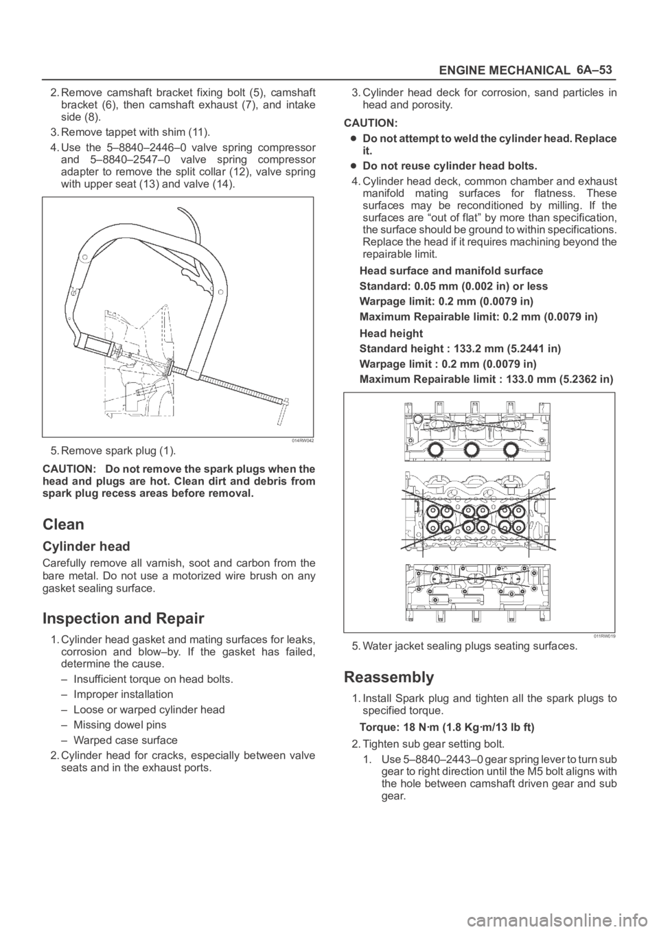
3. Remove tappet with shim (11).
4. Use the 5–8840–2446–0 valve spring compressor
and 5–8840–2547–0 valve spring compressor
adapter to remove the split collar (12), valve spring
with upper seat (13) and valve (14).
014RW042
5. Remove spark plug (1).
CAUTION: Do not remove the spark plugs when the
head and plugs are hot. Clean dirt and debris from
spark plug recess areas before removal.
Clean
Cylinder head
Carefully remove all varnish, soot and carbon from the
bare metal. Do not use a motorized wire brush on any
gasket sealing surface.
Inspection and Repair
1. Cylinder head gasket and mating surfaces for leaks,
corrosion and blow–by. If the gasket has failed,
determine the cause.
– Insufficient torque on head bolts.
– Improper installation
– Loose or warped cylinder head
– Missing dowel pins
– Warped case surface
2. Cylinder head for cracks, especially between valve
seats and in the exhaust ports.3. Cylinder head deck for corrosion, sand particles in
head and porosity.
CAUTION:
Do not attempt to weld the cylinder head. Replace
it.
Do not reuse cylinder head bolts.
4. Cylinder head deck, common chamber and exhaust
manifold mating surfaces for flatness. These
surfaces may be reconditioned by milling. If the
surfaces are “out of flat” by more than specification,
the surface should be ground to within specifications.
Replace the head if it requires machining beyond the
repairable limit.
Head surface and manifold surface
Standard: 0.05 mm (0.002 in) or less
Warpage limit: 0.2 mm (0.0079 in)
Maximum Repairable limit: 0.2 mm (0.0079 in)
Head height
Standard height : 133.2 mm (5.2441 in)
Warpage limit : 0.2 mm (0.0079 in)
Maximum Repairable limit : 133.0 mm (5.2362 in)
011RW019
5. Water jacket sealing plugs seating surfaces.
Reassembly
1. Install Spark plug and tighten all the spark plugs to
specified torque.
Torque: 18 Nꞏm (1.8 Kgꞏm/13 lb ft)
2. Tighten sub gear setting bolt.
1. Use 5–8840–2443–0 gear spring lever to turn sub
gear to right direction until the M5 bolt aligns with
the hole between camshaft driven gear and sub
gear.
Page 5345 of 6000
6A – 72 ENGINE MECHANICAL
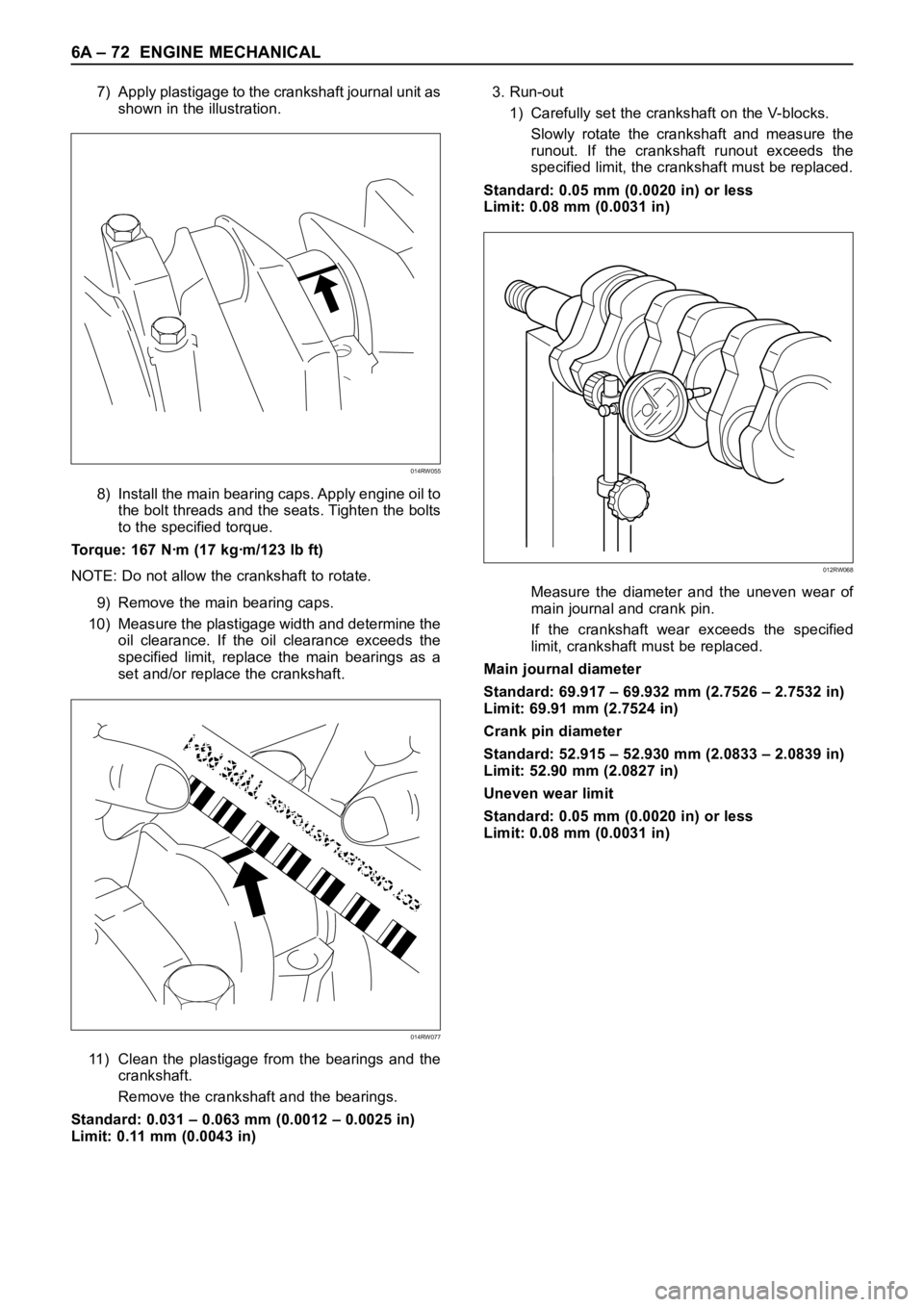
7) Apply plastigage to the crankshaft journal unit as
shown in the illustration.
8) Install the main bearing caps. Apply engine oil to
the bolt threads and the seats. Tighten the bolts
to the specified torque.
Torque: 167 Nꞏm (17 kgꞏm/123 lb ft)
NOTE: Do not allow the crankshaft to rotate.
9) Remove the main bearing caps.
10) Measure the plastigage width and determine the
oil clearance. If the oil clearance exceeds the
specified limit, replace the main bearings as a
set and/or replace the crankshaft.
11) Clean the plastigage from the bearings and the
crankshaft.
Remove the crankshaft and the bearings.
Standard: 0.031 – 0.063 mm (0.0012 – 0.0025 in)
Limit: 0.11 mm (0.0043 in)3. Run-out
1) Carefully set the crankshaft on the V-blocks.
Slowly rotate the crankshaft and measure the
runout. If the crankshaft runout exceeds the
specified limit, the crankshaft must be replaced.
Standard: 0.05 mm (0.0020 in) or less
Limit: 0.08 mm (0.0031 in)
Measure the diameter and the uneven wear of
main journal and crank pin.
If the crankshaft wear exceeds the specified
limit, crankshaft must be replaced.
Main journal diameter
Standard: 69.917 – 69.932 mm (2.7526 – 2.7532 in)
Limit: 69.91 mm (2.7524 in)
Crank pin diameter
Standard: 52.915 – 52.930 mm (2.0833 – 2.0839 in)
Limit: 52.90 mm (2.0827 in)
Uneven wear limit
Standard: 0.05 mm (0.0020 in) or less
Limit: 0.08 mm (0.0031 in)
014RW055
014RW077
012RW068