1998 OPEL FRONTERA drain bolt
[x] Cancel search: drain boltPage 4510 of 6000
6A–14
ENGINE MECHANICAL
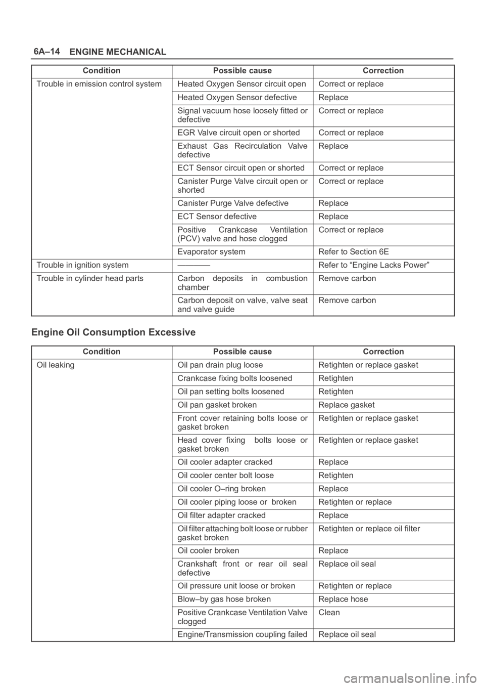
Condition CorrectionPossible cause
Trouble in emission control systemHeated Oxygen Sensor circuit openCorrect or replace
Heated Oxygen Sensor defectiveReplace
Signal vacuum hose loosely fitted or
defectiveCorrect or replace
EGR Valve circuit open or shortedCorrect or replace
Exhaust Gas Recirculation Valve
defectiveReplace
ECT Sensor circuit open or shortedCorrect or replace
Canister Purge Valve circuit open or
shortedCorrect or replace
Canister Purge Valve defectiveReplace
ECT Sensor defectiveReplace
Positive Crankcase Ventilation
(PCV) valve and hose cloggedCorrect or replace
Evaporator systemRefer to Section 6E
Trouble in ignition system————Refer to “Engine Lacks Power”
Trouble in cylinder head partsCarbon deposits in combustion
chamberRemove carbon
Carbon deposit on valve, valve seat
and valve guideRemove carbon
Engine Oil Consumption Excessive
ConditionPossible causeCorrection
Oil leakingOil pan drain plug looseRetighten or replace gasket
Crankcase fixing bolts loosenedRetighten
Oil pan setting bolts loosenedRetighten
Oil pan gasket brokenReplace gasket
Front cover retaining bolts loose or
gasket brokenRetighten or replace gasket
Head cover fixing bolts loose or
gasket brokenRetighten or replace gasket
Oil cooler adapter crackedReplace
Oil cooler center bolt looseRetighten
Oil cooler O–ring brokenReplace
Oil cooler piping loose or brokenRetighten or replace
Oil filter adapter crackedReplace
Oil filter attaching bolt loose or rubber
gasket brokenRetighten or replace oil filter
Oil cooler brokenReplace
Crankshaft front or rear oil seal
defectiveReplace oil seal
Oil pressure unit loose or brokenRetighten or replace
Blow–by gas hose brokenReplace hose
Positive Crankcase Ventilation Valve
cloggedClean
Engine/Transmission coupling failedReplace oil seal
Page 4533 of 6000
6A–37
ENGINE MECHANICAL
Cylinder Head
Removal
1. Remove engine hood.
2. Disconnect battery ground cable.
3. Drain radiator coolant.
4. Drain engine oil.
5. Remove crankshaft pulley.
Refer to removal procedure for Crankshaft Pulley in
this manual.
6. Remove timing belt.
Refer to removal procedure for Timing Belt in this
manual.
7. Remove cylinder head cover LH.
Refer to removal procedure for Cylinder Head
Cover LH in this manual.
8. Remove cylinder head cover RH.
Refer to removal procedure for Cylinder Head
Cover RH in this manual.
9. Remove common chamber.
Refer to removal procedure for Common Chamber
in this manual.
10. Remove cylinder head assembly.
1. Loosen eights bolts for tight cylinder head.
2. Remove cylinder head assembly.
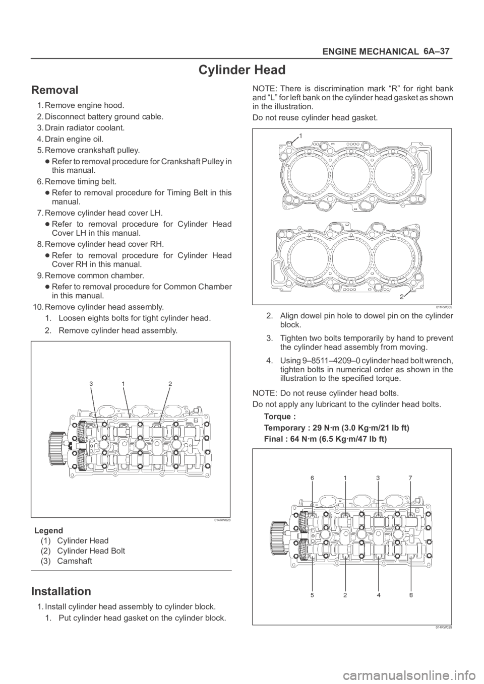
014RW028
Legend
(1) Cylinder Head
(2) Cylinder Head Bolt
(3) Camshaft
Installation
1. Install cylinder head assembly to cylinder block.
1. Put cylinder head gasket on the cylinder block.NOTE: There is discrimination mark “R” for right bank
and “L” for left bank on the cylinder head gasket as shown
in the illustration.
Do not reuse cylinder head gasket.
011RW005
2. Align dowel pin hole to dowel pin on the cylinder
block.
3. Tighten two bolts temporarily by hand to prevent
the cylinder head assembly from moving.
4. Using 9–8511–4209–0 cylinder head bolt wrench,
tighten bolts in numerical order as shown in the
illustration to the specified torque.
NOTE: Do not reuse cylinder head bolts.
Do not apply any lubricant to the cylinder head bolts.
To r q u e :
Temporary : 29 Nꞏm (3.0 Kgꞏm/21 lb ft)
Final : 64 Nꞏm (6.5 Kgꞏm/47 lb ft)
014RW029
Page 4544 of 6000
6A–48
ENGINE MECHANICAL
Engine Assembly
Removal
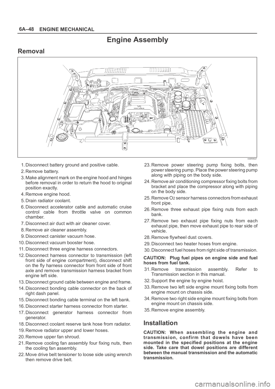
035RW027
1. Disconnect battery ground and positive cable.
2. Remove battery.
3. Make alignment mark on the engine hood and hinges
before removal in order to return the hood to original
position exactly.
4. Remove engine hood.
5. Drain radiator coolant.
6. Disconnect accelerator cable and automatic cruise
control cable from throttle valve on common
chamber.
7. Disconnect air duct with air cleaner cover.
8. Remove air cleaner assembly.
9. Disconnect canister vacuum hose.
10. Disconnect vacuum booster hose.
11. Disconnect three engine harness connectors.
12. Disconnect harness connector to transmission (left
front side of engine compartment), disconnect shift
on the fly harness connector from front side of front
axle and remove transmission harness bracket from
engine left side.
13. Disconnect ground cable between engine and frame.
14. Disconnect bonding cable connector on the back of
right dash panel.
15. Disconnect bonding cable terminal on the left bank.
16. Disconnect starter harness connector from starter.
17. Disconnect generator harness connector from
generator.
18. Disconnect coolant reserve tank hose from radiator.
19. Remove radiator upper and lower hoses.
20. Remove upper fan shroud.
21. Remove cooling fan assembly four fixing nuts, then
the cooling fan assembly.
22. Move drive belt tensioner to loose side using wrench
then remove drive belt.23. Remove power steering pump fixing bolts, then
power steering pump. Place the power steering pump
along with piping on the body side.
24. Remove air conditioning compressor fixing bolts from
bracket and place the compressor along with piping
on the body side.
25. Remove O
2 sensor harness connectors from exhaust
front pipe.
26. Remove three exhaust pipe fixing nuts from each
bank.
27. Remove two exhaust pipe fixing nuts from each
exhaust pipe, then move exhaust pipe to rear side of
vehicle.
28. Remove flywheel dust covers.
29. Disconnect two heater hoses from engine.
30. Disconnect fuel hoses from right side of transmission.
CAUTION: Plug fuel pipes on engine side and fuel
hoses from fuel tank.
31. Remove transmission assembly. Refer to
Transmission section in this manual.
32. Support the engine by engine hoist.
33. Remove two left side engine mount fixing bolts from
engine mount on chassis side.
34. Remove two right side engine mount fixing bolts from
engine mount on chassis side.
35. Remove engine assembly.
Installation
CAUTION: W h e n a s s e m b l i n g t h e e n g i n e a n d
transmission, confirm that dowels have been
mounted in the specified positions at the engine
side. Take care that dowel positions are different
between the manual transmission and the automatic
transmission.
Page 4600 of 6000
ENGINE COOLING6B–7
Water Pump
Water Pump and Associated Parts
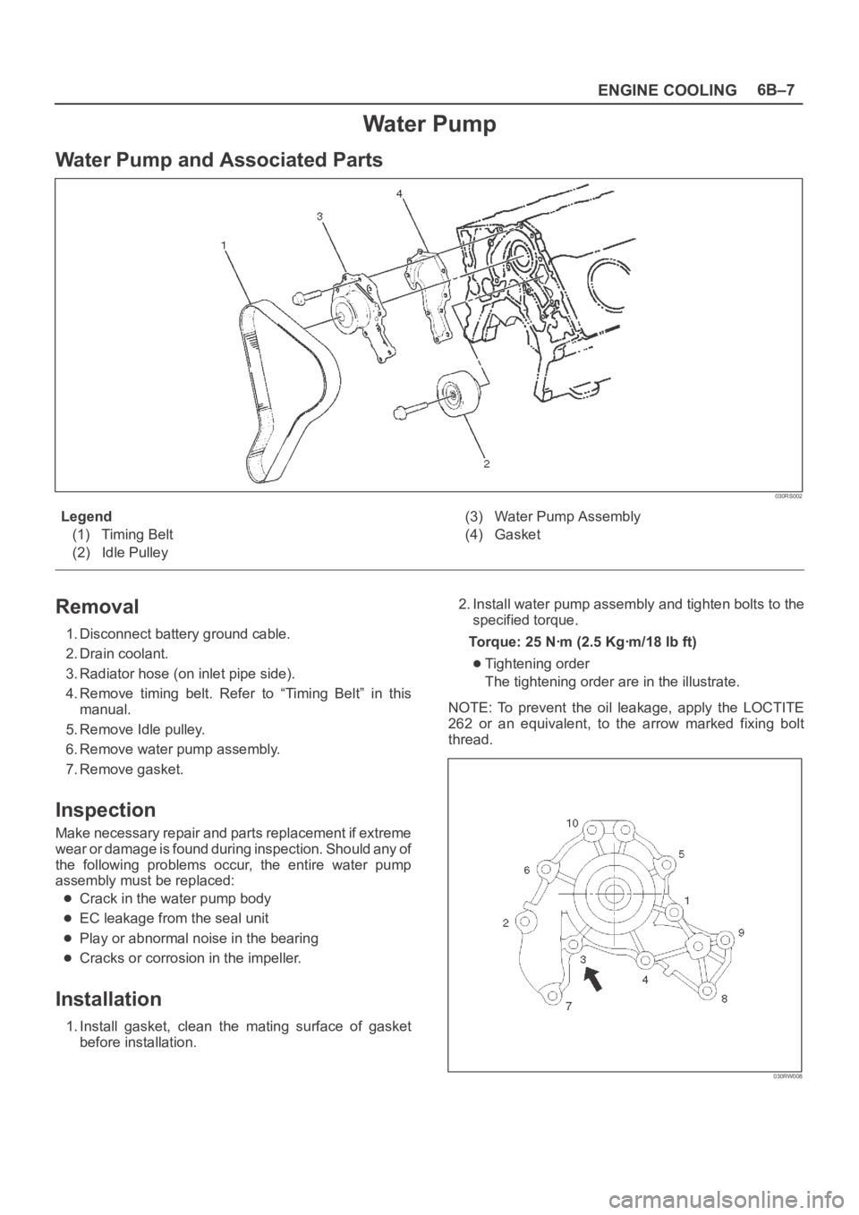
030RS002
Legend
(1) Timing Belt
(2) Idle Pulley(3) Water Pump Assembly
(4) Gasket
Removal
1. Disconnect battery ground cable.
2. Drain coolant.
3. Radiator hose (on inlet pipe side).
4. Remove timing belt. Refer to “Timing Belt” in this
manual.
5. Remove Idle pulley.
6. Remove water pump assembly.
7. Remove gasket.
Inspection
Make necessary repair and parts replacement if extreme
wear or damage is found during inspection. Should any of
the following problems occur, the entire water pump
assembly must be replaced:
Crack in the water pump body
EC leakage from the seal unit
Play or abnormal noise in the bearing
Cracks or corrosion in the impeller.
Installation
1. Install gasket, clean the mating surface of gasket
before installation.2. Install water pump assembly and tighten bolts to the
specified torque.
Torque: 25 Nꞏm (2.5 Kgꞏm/18 lb ft)
Tightening order
The tightening order are in the illustrate.
NOTE: To prevent the oil leakage, apply the LOCTITE
262 or an equivalent, to the arrow marked fixing bolt
thread.
030RW008
Page 4601 of 6000
6B–8
ENGINE COOLING
3. Idle pulley
Install idle pulley and tighten bolt to the specified
torque.
Torque: 52 Nꞏm (5.3 Kgꞏm/38 lb ft)4. Timing beltInstall timing belt. Refer to timing belt installation
step in “Timing Belt” in this manual.
5. Connect radiator inlet hose and replenish EC.
6. Connect battery ground cable.
Thermostat
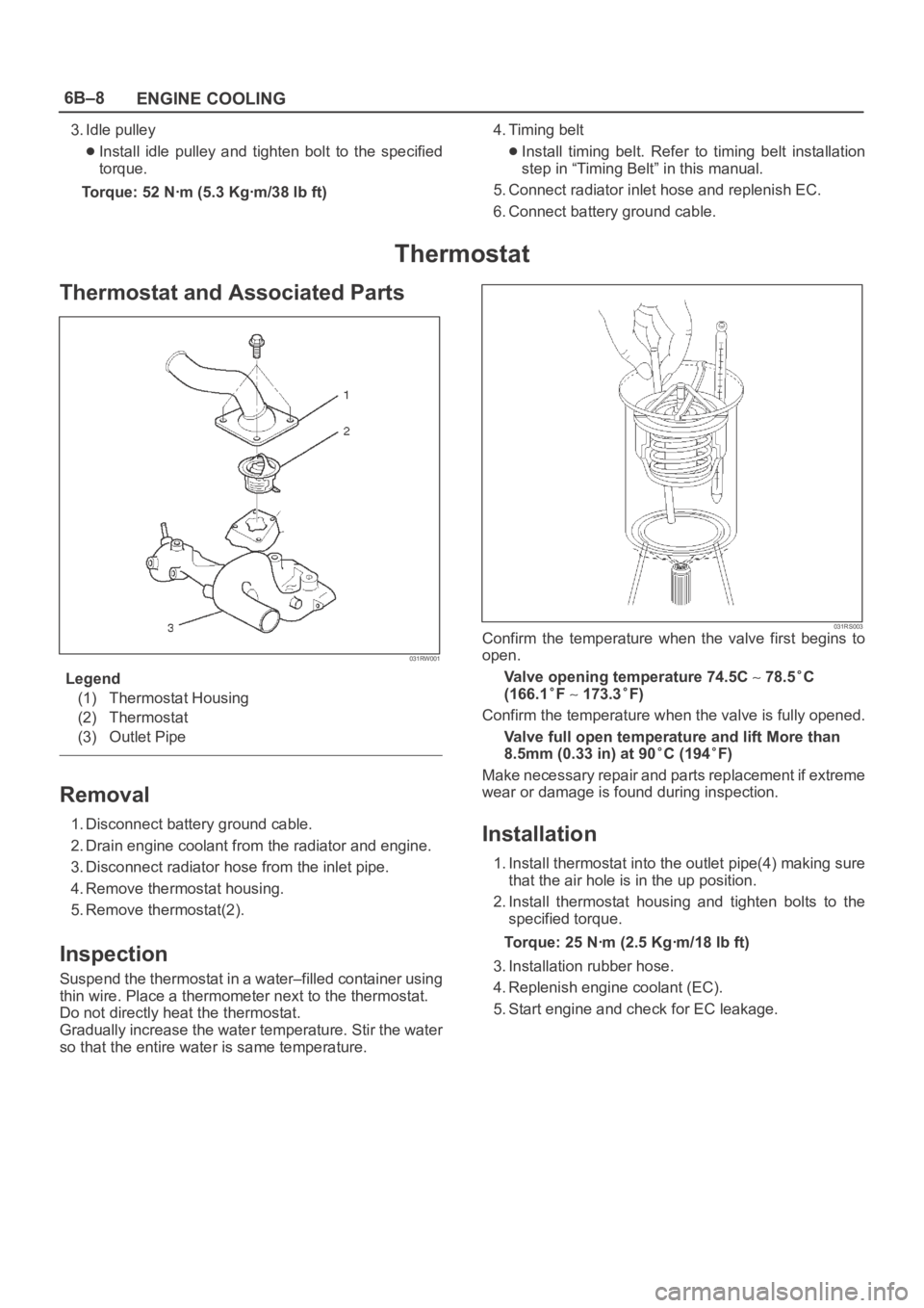
Thermostat and Associated Parts
031RW001
Legend
(1) Thermostat Housing
(2) Thermostat
(3) Outlet Pipe
Removal
1. Disconnect battery ground cable.
2. Drain engine coolant from the radiator and engine.
3. Disconnect radiator hose from the inlet pipe.
4. Remove thermostat housing.
5. Remove thermostat(2).
Inspection
Suspend the thermostat in a water–filled container using
thin wire. Place a thermometer next to the thermostat.
Do not directly heat the thermostat.
Gradually increase the water temperature. Stir the water
so that the entire water is same temperature.
031RS003Confirm the temperature when the valve first begins to
open.
Valve opening temperature 74.5C
78.5C
(166.1
F 173.3F)
Confirm the temperature when the valve is fully opened.
Valve full open temperature and lift More than
8.5mm (0.33 in) at 90
C (194F)
Make necessary repair and parts replacement if extreme
wear or damage is found during inspection.
Installation
1. Install thermostat into the outlet pipe(4) making sure
that the air hole is in the up position.
2. Install thermostat housing and tighten bolts to the
specified torque.
Torque: 25 Nꞏm (2.5 Kgꞏm/18 lb ft)
3. Installation rubber hose.
4. Replenish engine coolant (EC).
5. Start engine and check for EC leakage.
Page 4611 of 6000
6C–4
ENGINE FUEL
Fuel Filter
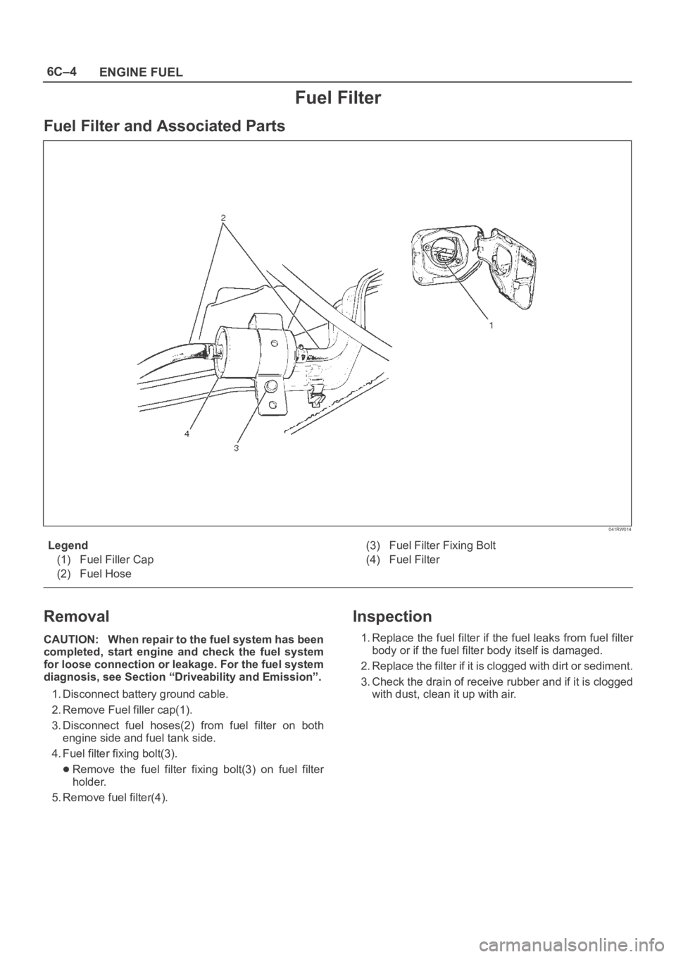
Fuel Filter and Associated Parts
041RW014
Legend
(1) Fuel Filler Cap
(2) Fuel Hose(3) Fuel Filter Fixing Bolt
(4) Fuel Filter
Removal
CAUTION: When repair to the fuel system has been
completed, start engine and check the fuel system
for loose connection or leakage. For the fuel system
diagnosis, see Section “Driveability and Emission”.
1. Disconnect battery ground cable.
2. Remove Fuel filler cap(1).
3. Disconnect fuel hoses(2) from fuel filter on both
engine side and fuel tank side.
4. Fuel filter fixing bolt(3).
Remove the fuel filter fixing bolt(3) on fuel filter
holder.
5. Remove fuel filter(4).
Inspection
1. Replace the fuel filter if the fuel leaks from fuel filter
body or if the fuel filter body itself is damaged.
2. Replace the filter if it is clogged with dirt or sediment.
3. Check the drain of receive rubber and if it is clogged
with dust, clean it up with air.
Page 4614 of 6000
6C–7
ENGINE FUEL
Fuel Pump Relay
General Description
In order to control the FP operation, the FP relay is
provided. When the starter switch is turned to “ON”
position, the FP relay operates the FP for 2 seconds.When it is turned to “START” position, the Power Train
Control Module (PCM) receives the reference pulse from
the Ignition Control Module and it operates the relay,
again causing the FP to feed fuel.
Fuel Tank
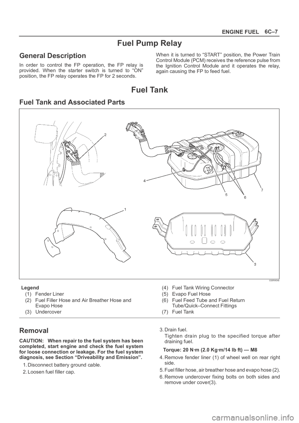
Fuel Tank and Associated Parts
035RW048
Legend
(1) Fender Liner
(2) Fuel Filler Hose and Air Breather Hose and
Evapo Hose
(3) Undercover(4) Fuel Tank Wiring Connector
(5) Evapo Fuel Hose
(6) Fuel Feed Tube and Fuel Return
Tube/Quick–Connect Fittings
(7) Fuel Tank
Removal
CAUTION: When repair to the fuel system has been
completed, start engine and check the fuel system
for loose connection or leakage. For the fuel system
diagnosis, see Section “Driveability and Emission”.
1. Disconnect battery ground cable.
2. Loosen fuel filler cap.3. Drain fuel.
Tighten drain plug to the specified torque after
draining fuel.
Torque: 20 Nꞏm (2.0 Kgꞏm/14 lb ft) — M8
4. Remove fender liner (1) of wheel well on rear right
side.
5. Fuel filler hose, air breather hose and evapo hose (2).
6. Remove undercover fixing bolts on both sides and
remove under cover(3).
Page 4662 of 6000
6E–5 ENGINE DRIVEABILITY AND EMISSIONS
Specifications
Tightening Specifications
ApplicationNꞏmLb Ft.Lb In.
Camshaft Position Sensor Retaining Screw9—78
Crankshaft Position Sensor Mounting Bolt10—87
EGR Bolt2821—
EGR Nut2821—
Engine Coolant Temperature Sensor207.7—
Fuel Drain Plug2922—
Fuel Pressure Regulator Attaching Screw6.5—60
Fuel Rail Bolts2518—
Fuel Tank Undercover Retaining Bolts3627—
Heated Oxygen Sensor4231—
Lower Intake Manifold to Engine Block Bolts2518—
Lower Intake Manifold to Engine Block Nuts2518—
Spark Plugs1813—
Throttle Body Mounting Bolts2518—
Upper Intake Manifold to Lower Intake Manifold Bolts2518—
VSS Retaining Bolt13—120
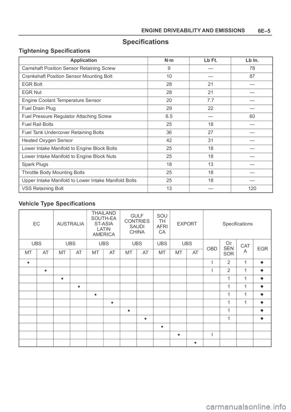
Vehicle Type Specifications
ECAUSTRALIA
THAILAND
SOUTH-EA
ST-ASIA
LATIN
AMERICAGULF
CONTRIES
SAUDI
CHINASOU
TH
AFRI
CA
EXPORTSpecifications
UBSUBSUBSUBSUBSUBS
OBD
O2
SENCATEGRMTATMTATMTATMTATMTMTATOBDSEN
SORAEGR
I21
I21
11
11
11
11
1
1
I