1998 OPEL FRONTERA rack
[x] Cancel search: rackPage 5726 of 6000
7A–37 AUTOMATIC TRANSMISSION (4L30–E)
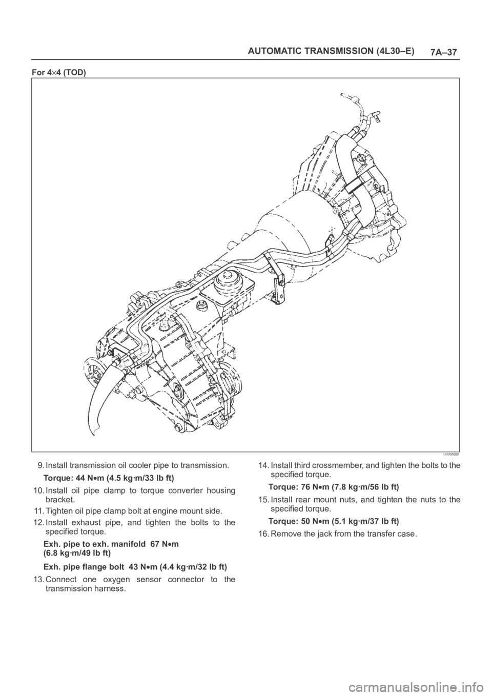
For 44 (TOD)
141RW001
9. Install transmission oil cooler pipe to transmission.
Torque: 44 N
m (4.5 kgꞏm/33 lb ft)
10. Install oil pipe clamp to torque converter housing
bracket.
11. Tighten oil pipe clamp bolt at engine mount side.
12. Install exhaust pipe, and tighten the bolts to the
specified torque.
Exh. pipe to exh. manifold 67 N
m
(6.8 kgꞏm/49 lb ft)
Exh. pipe flange bolt 43 N
m (4.4 kgꞏm/32 lb ft)
13. Connect one oxygen sensor connector to the
transmission harness.14. Install third crossmember, and tighten the bolts to the
specified torque.
To r q u e : 7 6 N
m (7.8 kgꞏm/56 lb ft)
15. Install rear mount nuts, and tighten the nuts to the
specified torque.
To r q u e : 5 0 N
m (5.1 kgꞏm/37 lb ft)
16. Remove the jack from the transfer case.
Page 5732 of 6000
7A–43 AUTOMATIC TRANSMISSION (4L30–E)
Valve Body Assembly (Adapter Case)
Removal
1. Raise the vehicle and support it on jack stands.
2. Disconnect battery ground cable.
3. Drain fluid.
4. Remove transfer and exhaust protectors.
5. Remove exhaust pipe and disconnect oxygen sensor
connector.
6. Remove twelve 10 mm adapter case oil pan fixing
screws, adapter case oil pan, and gasket.
NOTE: Oil pan still contains transmission fluid. Place a
large drain container under the oil pan.
Drain the fluid carefully.
7. Disconnect wiring harness from force motor solenoid
and converter clutch solenoid. Pull only on
connectors, not on wiring harness.
8. Remove seven 13 mm screws from adapter case
valve body assembly, then remove transfer plate, two
gaskets, and adapter case valve body.
Installation
1. Inspect electrical 5 pin connector and seal of adapter
case. Replace if necessary.2. Install gasket, transfer plate, and gasket.
3. Install adapter case valve body and seven 13 mm
screws. Tighten the screws to the specified torque.
To r q u e : 2 0 N
m (2.0 kgꞏm/15 lb ft)
4. Connect wiring harness assembly to converter clutch
solenoid and force motor.
5. Install oil pan gasket, oil pan, and twelve 10 mm
screws. Tighten the screws to the specified torque.
To r q u e : 11 N
m (1.1 kgꞏm/96 lb in)
6. Install exhaust pipe and connect oxygen sensor
connector. Tighten the bolts to the specified torque.
Exhaust pipe flange bolt torque:
43 N
m(4.4kgꞏm/32lbft)
7. Install transfer and exhaust protectors. Tighten the
bolts to the specified torque.
To r q u e : 3 7 N
m(3.8kgꞏm/27lbft)
8. Fill transmission through the overfill screw hole of oil
pan, using ATF DEXRON
–III. Refer to Changing
Transmission Fluid in this section.
9. Connect battery ground cable.
Powertrain Control Module (PCM)
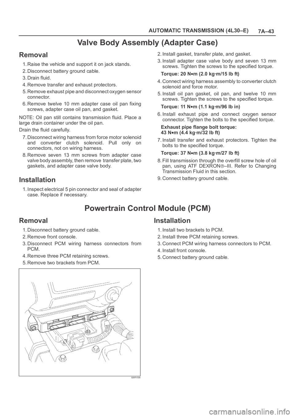
Removal
1. Disconnect battery ground cable.
2. Remove front console.
3. Disconnect PCM wiring harness connectors from
PCM.
4. Remove three PCM retaining screws.
5. Remove two brackets from PCM.
826RV006
Installation
1. Install two brackets to PCM.
2. Install three PCM retaining screws.
3. Connect PCM wiring harness connectors to PCM.
4. Install front console.
5. Connect battery ground cable.
Page 5752 of 6000
7A–63 AUTOMATIC TRANSMISSION (4L30–E)
10. Remove retainer (13), 2–3 shift valve (14), and spring
(15).
11. Remove spring pin (16), plug (17), spring (18), and
low pressure control valve (19).
12. Remove spring pin (20), plug (21), and band control
screen assembly (22).
13. Remove spring pin (23), plug (24), 1–2 accumulator
valve (25), and 1–2 accumulator control valve (26).
14. Remove check ball (27) from valve body (28).
Inspection And Repair
Inspect for the following, and replace any damaged or
worn parts:
1. Damage or wear to each valve.
2. Damage in oil passeges.
3. Cracks or damage to valve body.
4. Valve operations.
5. Spring fatigue.
Reassembly
1. Install 1–2 accumulator control valve (26), 1–2
accumulator valve (25), plug (24), and spring pin (23).
2. Install band control screen assembly (22), plug (21),
and spring pin (20).
3. Install low pressure control valve (19), spring (18),
plug (17), and spring pin (16).
4. Install spring (15), 2–3 shift valve (14), retainer (13),
solenoid B (12), and spring pin (11).
5. Install spring (10), 1–2/3–4 shift valve (9), retainer (8),
solenoid A (7), and spring pin (6).
6. Install waved washer (5), band control solenoid (3),
and pin (4).
7. Install manual valve (2).
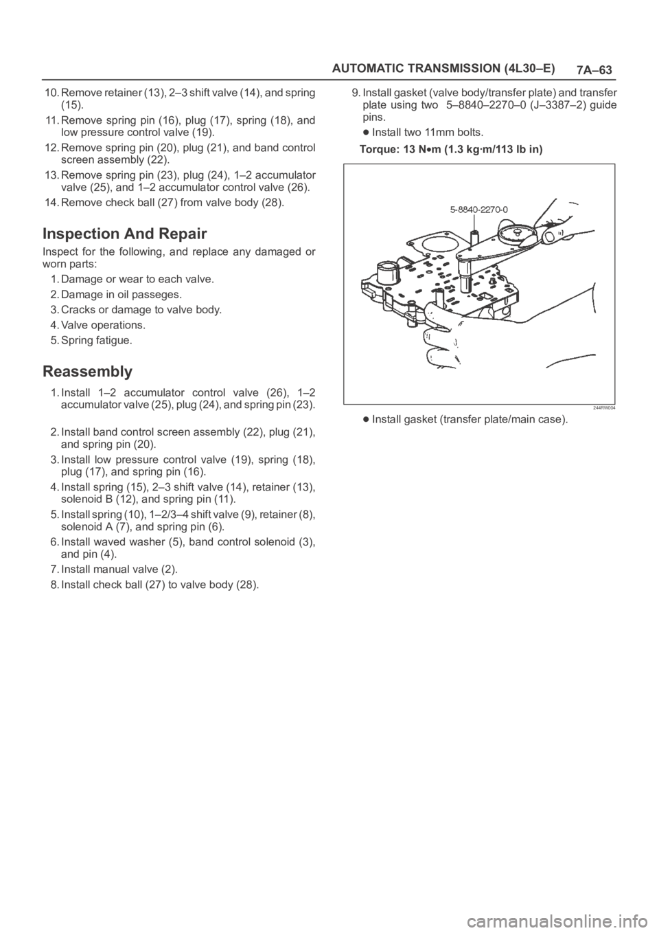
8. Install check ball (27) to valve body (28).9. Install gasket (valve body/transfer plate) and transfer
plate using two 5–8840–2270–0 (J–3387–2) guide
pins.
Install two 11mm bolts.
To r q u e : 1 3 N
m (1.3 kgꞏm/113 lb in)
244RW004
Install gasket (transfer plate/main case).
Page 5753 of 6000
7A–64
AUTOMATIC TRANSMISSION (4L30–E)
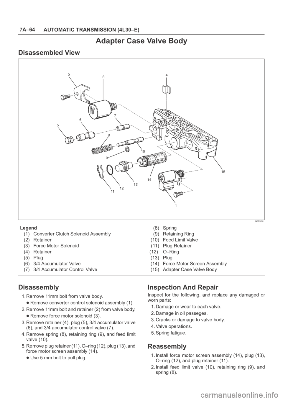
Adapter Case Valve Body
Disassembled View
243RW001
Legend
(1) Converter Clutch Solenoid Assembly
(2) Retainer
(3) Force Motor Solenoid
(4) Retainer
(5) Plug
(6) 3/4 Accumulator Valve
(7) 3/4 Accumulator Control Valve(8) Spring
(9) Retaining Ring
(10) Feed Limit Valve
(11) Plug Retainer
(12) O–Ring
(13) Plug
(14) Force Motor Screen Assembly
(15) Adapter Case Valve Body
Disassembly
1. Remove 11mm bolt from valve body.
Remove converter control solenoid assembly (1).
2. Remove 11mm bolt and retainer (2) from valve body.
Remove force motor solenoid (3).
3. Remove retainer (4), plug (5), 3/4 accumulator valve
(6), and 3/4 accumulator control valve (7).
4. Remove spring (8), retaining ring (9), and feed limit
valve (10).
5. Remove plug retainer (11), O–ring (12), plug (13), and
force motor screen assembly (14).
Use 5 mm bolt to pull plug.
Inspection And Repair
Inspect for the following, and replace any damaged or
worn parts:
1. Damage or wear to each valve.
2. Damage in oil passeges.
3. Cracks or damage to valve body.
4. Valve operations.
5. Spring fatigue.
Reassembly
1. Install force motor screen assembly (14), plug (13),
O–ring (12), and plug retainer (11).
2. Install feed limit valve (10), retaining ring (9), and
spring (8).
Page 5862 of 6000
AUTOMATIC TRANSMISSION (AW30-40LE) 7A–81
256RW014
256RW015
INSTALLATION
To install, follow the removal steps in the reverse order, noting
the following points;
Adjustment of select lever and control rod
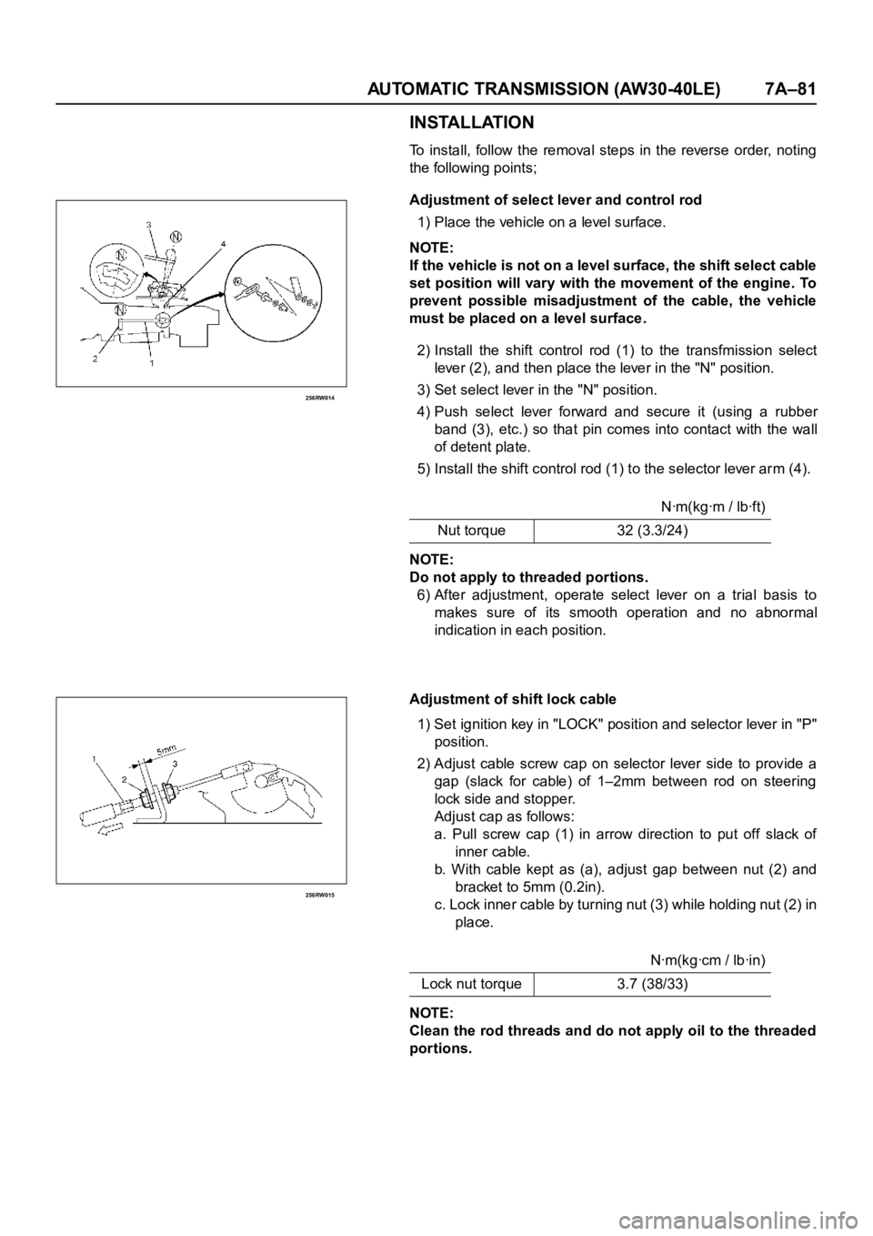
1) Place the vehicle on a level surface.
NOTE:
If the vehicle is not on a level surface, the shift select cable
set position will vary with the movement of the engine. To
prevent possible misadjustment of the cable, the vehicle
must be placed on a level surface.
2) Install the shift control rod (1) to the transfmission select
lever (2), and then place the lever in the "N" position.
3) Set select lever in the "N" position.
4) Push select lever forward and secure it (using a rubber
band (3), etc.) so that pin comes into contact with the wall
of detent plate.
5) Install the shift control rod (1) to the selector lever arm (4).
NOTE:
Do not apply to threaded portions.
6) After adjustment, operate select lever on a trial basis to
makes sure of its smooth operation and no abnormal
indication in each position.
Adjustment of shift lock cable
1) Set ignition key in "LOCK" position and selector lever in "P"
position.
2) Adjust cable screw cap on selector lever side to provide a
gap (slack for cable) of 1–2mm between rod on steering
lock side and stopper.
Adjust cap as follows:
a. Pull screw cap (1) in arrow direction to put off slack of
inner cable.
b. With cable kept as (a), adjust gap between nut (2) and
bracket to 5mm (0.2in).
c. Lock inner cable by tur ning nut (3) while holding nut (2) in
place.
NOTE:
Clean the rod threads and do not apply oil to the threaded
portions.Nꞏm(kgꞏm / lbꞏft)
Nut torque 32 (3.3/24)
Nꞏm(kgꞏcm / lbꞏin)
Lock nut torque 3.7 (38/33)
Page 5864 of 6000
AUTOMATIC TRANSMISSION (AW30-40LE) 7A–83
826RY00005
826RY00006
249RY00011
249RY00012
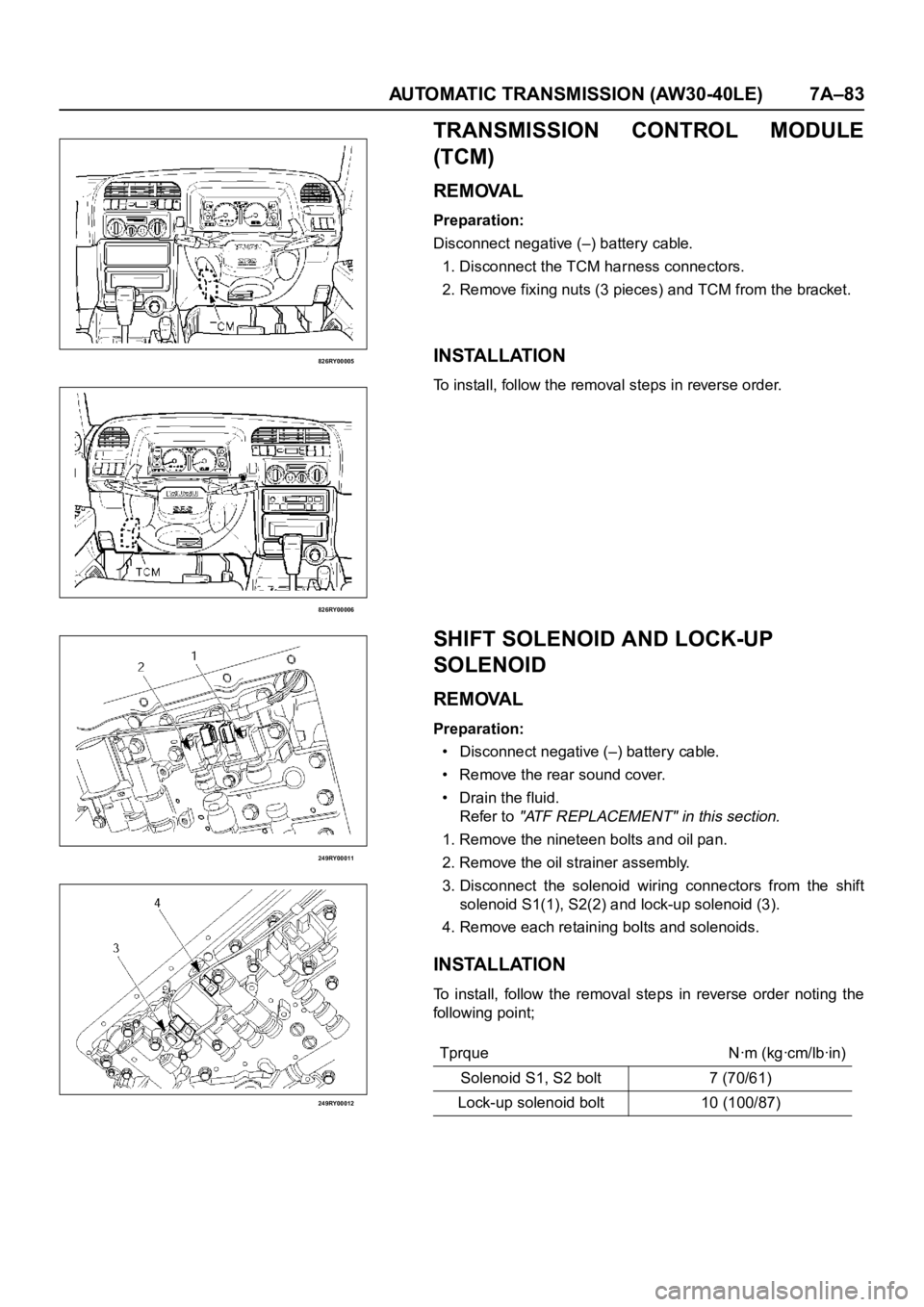
TRANSMISSION CONTROL MODULE
(TCM)
REMOVAL
Preparation:
Disconnect negative (–) battery cable.
1. Disconnect the TCM harness connectors.
2. Remove fixing nuts (3 pieces) and TCM from the bracket.
INSTALLATION
To install, follow the removal steps in reverse order.
SHIFT SOLENOID AND LOCK-UP
SOLENOID
REMOVAL
Preparation:
• Disconnect negative (–) battery cable.
• Remove the rear sound cover.
• Drain the fluid.
Refer to
"ATF REPLACEMENT" in this section.
1. Remove the nineteen bolts and oil pan.
2. Remove the oil strainer assembly.
3. Disconnect the solenoid wiring connectors from the shift
solenoid S1(1), S2(2) and lock-up solenoid (3).
4. Remove each retaining bolts and solenoids.
INSTALLATION
To install, follow the removal steps in reverse order noting the
following point;
Tprque Nꞏm (kgꞏcm/lbꞏin)
Solenoid S1, S2 bolt 7 (70/61)
Lock-up solenoid bolt 10 (100/87)
Page 5891 of 6000
7A–110 AUTOMATIC TRANSMISSION (AW30-40LE)
241RY00009
241RY00010
241RY00011
241RY00012
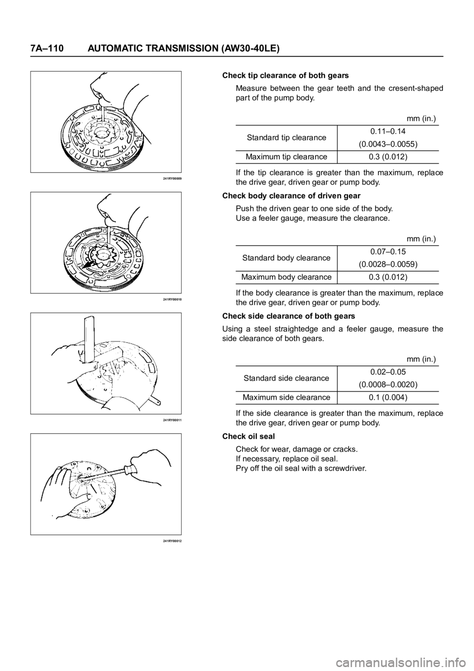
Check tip clearance of both gears
Measure between the gear teeth and the cresent-shaped
par t of the pump body.
If the tip clearance is greater than the maximum, replace
the drive gear, driven gear or pump body.
Check body clearance of driven gear
Push the driven gear to one side of the body.
Use a feeler gauge, measure the clearance.
If the body clearance is greater than the maximum, replace
the drive gear, driven gear or pump body.
Check side clearance of both gears
Using a steel straightedge and a feeler gauge, measure the
side clearance of both gears.
If the side clearance is greater than the maximum, replace
the drive gear, driven gear or pump body.
Check oil seal
Check for wear, damage or cracks.
If necessary, replace oil seal.
Pry off the oil seal with a screwdriver.mm (in.)
Standard tip clearance0.11–0.14
(0.0043–0.0055)
Maximum tip clearance 0.3 (0.012)
mm (in.)
Standard body clearance0.07–0.15
(0.0028–0.0059)
Maximum body clearance 0.3 (0.012)
mm (in.)
Standard side clearance0.02–0.05
(0.0008–0.0020)
Maximum side clearance 0.1 (0.004)