Page 5648 of 6000
6E–219 4JX1–TC ENGINE DRIVEABILITY AND EMISSIONS
2. Install the MAP sensor assembly and EGR VSV and
tighten MAP sensor bracket fixing bolts specified
torque.
Torque: 9 Nꞏm (78 lb in)
035RW067
3. Connect the EGR VSV connector and vacuum hose
in the EGR VSV.
035RW063
4. Connect the negative battery cable.
Electronic Vacuum Regurating
Va l v e ( E V RV )
Removal Procedure
1. Disconnect the negative battery cable.
2. Disconnect the EVRV hose and the EVRV connector.
035RW065
3. Remove the EVRV.
035RW064
Page 5656 of 6000

6E–227 4JX1–TC ENGINE DRIVEABILITY AND EMISSIONS
QOS
Diagnostics
– Malfunction Indicator Lamp (Service Engine
Soon lamp)
– Data Link Connector (DLC)
– Data Output
ECM Service Precautions
The ECM is designed to withstand normal current draws
associated with vehicle operation. Avoid overloading any
circuit. When testing for opens and shorts, do not ground
or apply voltage to any of the ECM’s circuits unless
instructed to do so. These circuits should only be tested
using digital voltmeter. The ECM should remain
connected to the ECM or to a recommended breakout
box.
Intake Throttle Position (ITP) Sensor
ITP sensor is a potentiometer type and installed to the
intake throttle valve body. A voltage of 5V is applied
constantly from ECM to ITP sensor thereby to determine
by change in voltage the opening of the intake throttle
valve during warming up.
Transmission Range Switch
IMPORTANT:The vehicle should not be driven with the
transmission range switch disconnected; idle quality will
be affected.
The four inputs from the transmission range switch
indicate to the ECM which position is selected by the
transmission selector lever.
For more information on the transmission on the
transmission range switch, refer to
Automatic
Tr a n s m i s s i o n
.
Accelerator Position Sensor (AP)
AP sensor is a potentiometer type and installed to
accelerator pedal bracket. A voltage of 5V constantly
applied from ECM to the sensor thereby to determine the
accelerator pedaling angle by change in voltage. Further,
this sensor is provided with an accelerator switch, which
is set off only when the accelerator pedal is stepped on.
Aftermarket Electrical and Vacuum
Equipment
Aftermarket (add-on) electrical and vacuum equipment is
defined as any equipment which connects to the vehicle’s
electrical or vacuum systems that is installed on a vehicle
after it leaves the factory. No allowances have been
made in the vehicle design for this type of equipment.
NOTE: No add-on vacuum equipment should be added
to this vehicle.
NOTE: Add-on electrical equipment must only be
connected to the vehicle’s electrical system at the battery
(power and ground).
Add-on electrical equipment, even when installed to
these guidelines, may still cause the powertrain system to
malfunction. This may also include equipment not
connected to the vehicle electrical system such asportable telephones and radios. Therefore, the first step
in diagnosing any powertrain problem is to eliminate all
aftermarket electrical equipment from the vehicle. After
this is done, if the problem still exists, it may be diagnosed
in the normal manner.
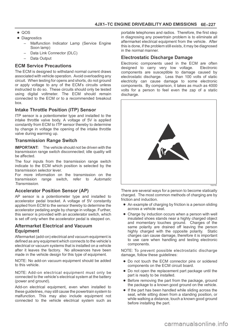
Electrostatic Discharge Damage
Electronic components used in the ECM are often
designed to carry very low voltage. Electronic
components are susceptible to damage caused by
electrostatic discharge. Less than 100 volts of static
electricity can cause damage to some electronic
components. By comparison, it takes as much as 4000
volts for a person to feel even the zap of a static
discharge.
TS23793
There are several ways for a person to become statically
charged. The most common methods of charging are by
friction and induction.
An example of charging by friction is a person sliding
across a vehicle seat.
Charge by induction occurs when a person with well
insulated shoes stands near a highly charged object
and momentary touches ground. Charges of the
same polarity are drained off leaving the person
highly charged with the opposite polarity. Static
charges can cause damage, therefore it is important
to use care when handling and testing electronic
components.
NOTE: To prevent possible electrostatic discharge
damage, follow these guidelines:
Do not touch the ECM connector pins or soldered
components on the ECM circuit board.
Do not open the replacement part package until the
part is ready to be installed.
Before removing the part from the package, ground
the package to a known good ground on the vehicle.
If the part has been handled while sliding across the
seat, while sitting down from a standing position, or
while walking a distance, touch a known good ground
before installing the part.
Page 5662 of 6000
ENGINE EXHAUST 6F – 3
ON-VEHICLE SERVICE
FRONT EXHAUST PIPE
Rattles and noise vibrations in the exhaust system are
usually caused by misalignment of parts. When aligning
the system, leave all bolts or nuts loose until all parts
are properly aligned; then tighten, working from front to
rear.
1. Check connections for looseness or damage,
especially for exhaust gas leakage.
2. Check clamps and rubbers for weakness, cracks or
damage.3. If any part of the converter heat shield is damaged
or dented to the extent that it contacts the catalyst,
repair or replace.
4. Check for dents or damage and for any holes or
cracks caused by corrosion.
3
2 1
Legend
(1) Front exhaust pipe
(2) Center exhaust pipe
(3) Mounting rubber
150RW071
Page 5663 of 6000

6F – 4 ENGINE EXHAUST
REMOVAL
1. Battery negative cable.
2. Raise the vehicle and support with suitable safety
stands.
3. Remove front exhaust pipe fixing nuts from engine
side.
4. Remove fixing nuts between front exhaust pipe and
center exhaust pipe, remove front exhaust pipe.
5. Disconnect center exhaust pipe and silencer,
remove center exhaust pipe.
6. Remove fixing nuts from connection part of tail pipe,
remove mounting rubber and remove silencer
bracket, silencer.
7. Remove mounting rubber for tail pipe, remove tail
pipe.
INSTALLATION
1. Install front exhaust pipe and tighten it temporarily.
2. Tighten fixing nuts of front exhaust pipe to the
specified torque. (for engine side)
Torque: 67 Nꞏm (6.8 kgꞏm/50 lb ft)
3. Tighten fixing nuts of front exhaust pipe to the
specified torque. (for center pipe side)
Torque: 43 Nꞏm (4.4 kgꞏm/32 lb ft)
4. Install silencer and tighten silencer bracket nuts to
the specified torque.
Torque: 16 Nꞏm (1.6 kgꞏm/12 lb ft)
5. Install tail pipe and tighten it.
Torque: 43 Nꞏm (4.4 kgꞏm/32 lb ft)
6. Install mounting rubbers.
Page 5665 of 6000
6F – 6 ENGINE EXHAUST
EXHAUST SILENCER
REMOVAL
1. Battery negative cable.
2. Raise the vehicle and support with suitable safety
stands.
3. Remove mounting rubber from silencer.
4. Remove silencer mounting bracket.
5. Remove fixing nuts between center exhaust pipe
and silencer.
6. Remove fixing nuts from tail pipe flange.
7. Remove silencer assembly.
INSTALLATION
1. Place silencer assembly in the original installation
position, tighten both side (front and rear) nuts
temporarily.
2. Tighten silencer mounting bracket to the specified
torque.
Torque : 16 Nꞏm (1.6 kgꞏm/12 lb ft)
3. Tighten center exhaust pipe side nuts to the
specified torque.
Torque : 43 Nꞏm (4.4 kgꞏm/32 lb ft)
4. Tighten tail pipe side nuts to the specified torque.
Torque : 43 Nꞏm (4.4 kgꞏm/32 lb ft)
5. Install silencer mounting rubber.
6
3
4
2
1
5
Legend
(1) Mounting Rubber
(2) Post Silencer
(3) Silencer(4) Mounting Bracket
(5) Mounting Rubber
(6) Tail Pipe
150RW072
Page 5666 of 6000
ENGINE EXHAUST 6F – 7
REAR EXHAUST PIPE
REMOVAL
1. Battery negative cable.
2. Raise the vehicle and support with suitable safety
stands.
3. Remove mounting rubber from post silencer.
4. Remove fixing nuts at silencer side.
5. Remove tail pipe together with post silencer.
6. Remove fixing nuts between tail pipe and post
silencer which separates them.
INSTALLATION
1. Install tail pipe and post silencer and tighten them to
the specified torque.
Torque : 43 Nꞏm (4.4 kgꞏm/32 lb ft)
2. Place tail pipe together with post silencer to original
position and tighten fixing nuts at silencer side.
Torque : 43 Nꞏm (4.4 kgꞏm/32 lb ft)
3. Install mounting rubber for post silencer.
4. Lower the vehicle.
5. Reconnect battery negative cable.
6
3
4
2
1
5
Legend
(1) Mounting Rubber
(2) Post Silencer
(3) Silencer(4) Mounting Bracket
(5) Mounting Rubber
(6) Tail Pipe
150RW072
Page 5675 of 6000

6H – 2 ENGINE SPEED CONTROL
GENERAL DESCRIPTION
3For A/T
1For M/T
2
1
101RW012
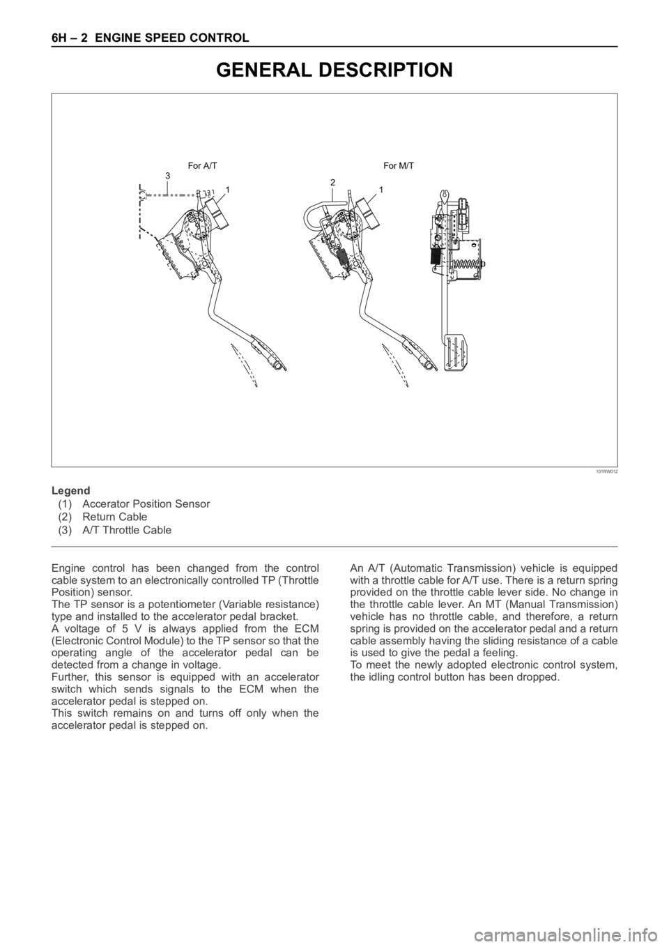
Engine control has been changed from the control
cable system to an electronically controlled TP (Throttle
Position) sensor.
The TP sensor is a potentiometer (Variable resistance)
type and installed to the accelerator pedal bracket.
A voltage of 5 V is always applied from the ECM
(Electronic Control Module) to the TP sensor so that the
operating angle of the accelerator pedal can be
detected from a change in voltage.
Further, this sensor is equipped with an accelerator
switch which sends signals to the ECM when the
accelerator pedal is stepped on.
This switch remains on and turns off only when the
accelerator pedal is stepped on.An A/T (Automatic Transmission) vehicle is equipped
with a throttle cable for A/T use. There is a return spring
provided on the throttle cable lever side. No change in
the throttle cable lever. An MT (Manual Transmission)
vehicle has no throttle cable, and therefore, a return
spring is provided on the accelerator pedal and a return
cable assembly having the sliding resistance of a cable
is used to give the pedal a feeling.
To meet the newly adopted electronic control system,
the idling control button has been dropped. Legend
(1) Accerator Position Sensor
(2) Return Cable
(3) A/T Throttle Cable
Page 5683 of 6000

6J – 6 INDUCTION
Legend
(1) Pressure gauge
(2) Waste gate control rod
4) Check for cracks or breaks on the hose, if a
problem is found, the hose must be replaced.
CAUTION: Do not apply more than 120 Kpa (900
mmHg / 18.7 PSi) to waste gate actuator.
INSTALLATION
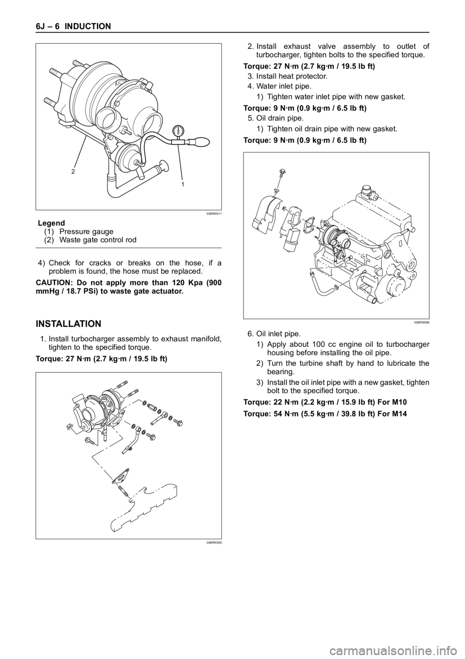
1. Install turbocharger assembly to exhaust manifold,
tighten to the specified torque.
Torque: 27 Nꞏm (2.7 kgꞏm / 19.5 lb ft)2. Install exhaust valve assembly to outlet of
turbocharger, tighten bolts to the specified torque.
Torque: 27 Nꞏm (2.7 kgꞏm / 19.5 lb ft)
3. Install heat protector.
4. Water inlet pipe.
1) Tighten water inlet pipe with new gasket.
Torque: 9 Nꞏm (0.9 kgꞏm / 6.5 lb ft)
5. Oil drain pipe.
1) Tighten oil drain pipe with new gasket.
Torque: 9 Nꞏm (0.9 kgꞏm / 6.5 lb ft)
6. Oil inlet pipe.
1) Apply about 100 cc engine oil to turbocharger
housing before installing the oil pipe.
2) Turn the turbine shaft by hand to lubricate the
bearing.
3) Install the oil inlet pipe with a new gasket, tighten
bolt to the specified torque.
Torque: 22 Nꞏm (2.2 kgꞏm / 15.9 lb ft) For M10
Torque: 54 Nꞏm (5.5 kgꞏm / 39.8 lb ft) For M14
2
1
036RW011
036RW005
036RW006