Page 5354 of 6000

ENGINE MECHANICAL 6A – 81
DISASSEMBLY
1. Cylinder Head Assembly
1) Refer to “Cylinder head” in this manual.
2. Crank Case Assembly
1) Refer to “Crank Case” in this manual.
3. Connecting Rod Bearing Cap
4. Piston and Connecting Rod
1) Remove carbon deposits from the upper portion
of the cylinder wall with a scraper before
removing the piston and connecting rod.
5. Piston Ring
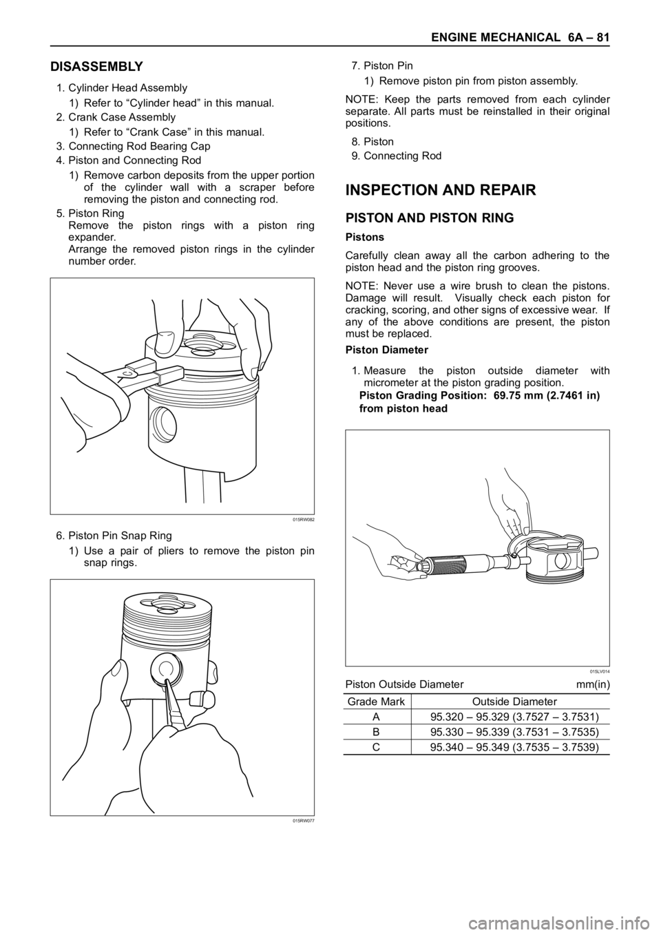
Remove the piston rings with a piston ring
expander.
Arrange the removed piston rings in the cylinder
number order.
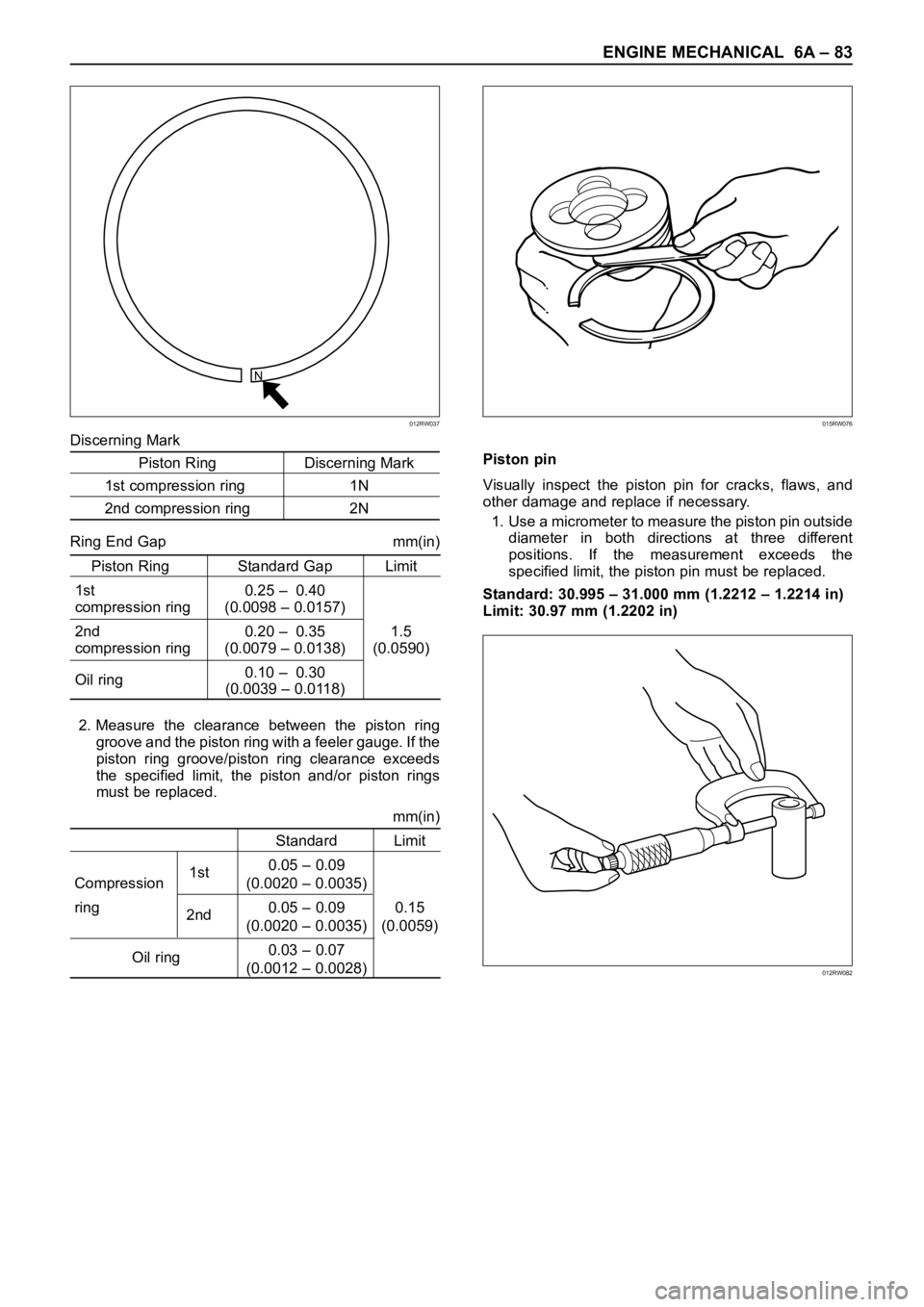
6. Piston Pin Snap Ring
1) Use a pair of pliers to remove the piston pin
snap rings.7. Piston Pin
1) Remove piston pin from piston assembly.
NOTE: Keep the parts removed from each cylinder
separate. All parts must be reinstalled in their original
positions.
8. Piston
9. Connecting Rod
INSPECTION AND REPAIR
PISTON AND PISTON RING
Pistons
Carefully clean away all the carbon adhering to the
piston head and the piston ring grooves.
NOTE: Never use a wire brush to clean the pistons.
Damage will result. Visually check each piston for
cracking, scoring, and other signs of excessive wear. If
any of the above conditions are present, the piston
must be replaced.
Piston Diameter
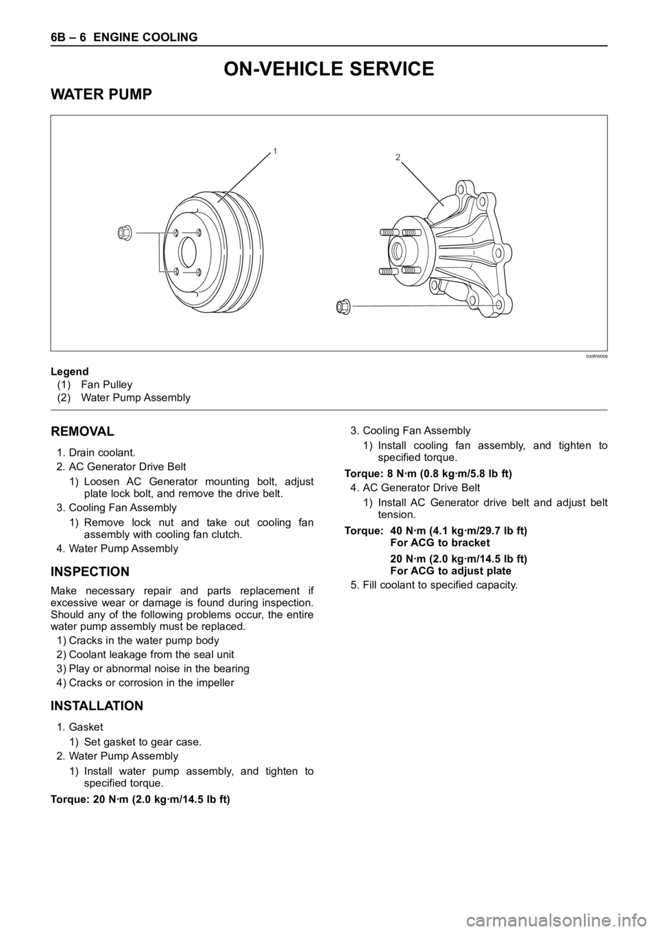
1. Measure the piston outside diameter with
micrometer at the piston grading position.
Piston Grading Position: 69.75 mm (2.7461 in)
from piston head
Piston Outside Diameter mm(in)
Grade Mark Outside Diameter
A 95.320 – 95.329 (3.7527 – 3.7531)
B 95.330 – 95.339 (3.7531 – 3.7535)
C 95.340 – 95.349 (3.7535 – 3.7539)
015RW082
015RW077
015LV014
Page 5356 of 6000

ENGINE MECHANICAL 6A – 83
Discerning Mark
Piston Ring Discerning Mark
1st compression ring 1N
2nd compression ring 2N
Ring End Gap mm(in)
Piston Ring Standard Gap Limit
1st 0.25 – 0.40
compression ring (0.0098 – 0.0157)
2nd 0.20 – 0.35 1.5
compression ring (0.0079 – 0.0138) (0.0590)
Oil ring0.10 – 0.30
(0.0039 – 0.0118)
2. Measure the clearance between the piston ring
groove and the piston ring with a feeler gauge. If the
piston ring groove/piston ring clearance exceeds
the specified limit, the piston and/or piston rings
must be replaced.
mm(in)
Standard Limit
1st0.05 – 0.09
Compression (0.0020 – 0.0035)
ring
2nd0.05 – 0.09 0.15
(0.0020 – 0.0035) (0.0059)
Oil ring0.03 – 0.07
(0.0012 – 0.0028)Piston pin
Visually inspect the piston pin for cracks, flaws, and
other damage and replace if necessary.
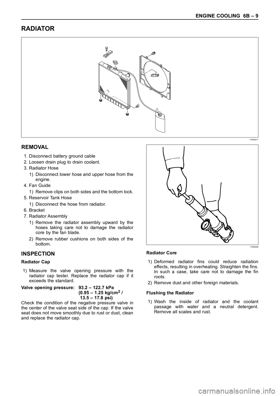
1. Use a micrometer to measure the piston pin outside
diameter in both directions at three different
positions. If the measurement exceeds the
specified limit, the piston pin must be replaced.
Standard: 30.995 – 31.000 mm (1.2212 – 1.2214 in)
Limit: 30.97 mm (1.2202 in)
N
012RW037015RW076
012RW082
Page 5374 of 6000

ENGINE COOLING 6B – 5
ENGINE COOLANT CHANGE
PROCEDURE
1. To change engine coolant, make sure that the
engine is cool.
WARNING:
When the coolant is heated to a high temperature,
be sure not to loosen or remove the radiator cap.
Otherwise you might get scalded by hot vapor or
boiling water. To open the radiator cap, put a piece
of thick cloth on the cap and loosen the cap slowly
to reduce the pressure once the coolant has
become cooler.
2. Open radiator cap and drain the cooling system by
loosening the drain valve on the radiator and on the
cylinder body.
NOTE: For best results it is suggested that the engine
cooling system be flushed at least once a year. It is
advisable to flush the interior of the cooling system
including the radiator before using anti-freeze
(ethylene-glycol based).
Replace damaged rubber hoses as the engine anti-
freeze coolant is liable to leak out even minor cracks.
Isuzu recommends using Isuzu genuine anti-freeze
(ethylene-glycol based) or equivalent, for the cooling
system and not add any inhibitors or additives.
CAUTION:
A failure to correctly fill the engine cooling system
in changing or topping off coolant may sometimes
cause the coolant to overflow from the filler neck
even before the engine and radiator are completely
full.
If the engine runs under this condition, shortage of
coolant may possibly result in engine overheating.
To avoid such trouble, the following precautions
should be taken in filling the system.
3. To refill engine coolant, pour coolant up to filler neck
using a filling hose which is smaller in outside
diameter than the filler neck. Otherwise air between
the filler neck and the filling hose will block entry,
preventing the system from completely filling up.
4. Keep a filling rate of 9 liter/min. or less. Filling over
this maximum rate may force air inside the engine
and radiator.
And also, the coolant overflow will increase, making
it difficult to determine whether or not the system is
completely full.
5. After filling the system full, pull out the filling hose
and check to see if air trapped in the system is
dislodged and the coolant level goes down. Should
the coolant level go down, repeat topping-off until
there is no more drop in the coolant level.
6. Directly after filling the radiator, fill the reservoir to
the maximum level.
7. Install and tighten radiator cap and start the engine.
After idling for 2 to 3 minutes, stop the engine and
reopen radiator cap. If the water level is lower,
replenish.WARNING:
When the coolant is heated to a high temperature,
be sure not to loosen or remove the radiator cap.
Otherwise you might get scalded by hot vapor or
boiling water. To open the radiator cap, put a piece
of thick cloth on the cap and loosen the cap slowly
to reduce the pressure once the coolant has
become cooler.
8. After tightening radiator cap, warm up the engine at
about 2,000 rpm.
Set heater adjustment to the highest temperature
position, and let the coolant circulate also into
heater water system.
9. Check to see the thermostat has opened by the
needle position of a water thermometer, conduct a
5-minute idle again and stop the engine.
10. When the engine has been cooled, check filler neck
for water level and replenish if required. Should
extreme shortage of coolant be found, check the
coolant system and reservoir tank hose for leakage.
11. Fill the coolant into the reservoir tank up to “MAX”
line.
Page 5375 of 6000

6B – 6 ENGINE COOLING
REMOVAL
1. Drain coolant.
2. AC Generator Drive Belt
1) Loosen AC Generator mounting bolt, adjust
plate lock bolt, and remove the drive belt.
3. Cooling Fan Assembly
1) Remove lock nut and take out cooling fan
assembly with cooling fan clutch.
4. Water Pump Assembly
INSPECTION
Make necessary repair and parts replacement if
excessive wear or damage is found during inspection.
Should any of the following problems occur, the entire
water pump assembly must be replaced.
1) Cracks in the water pump body
2) Coolant leakage from the seal unit
3) Play or abnormal noise in the bearing
4) Cracks or corrosion in the impeller
INSTALLATION
1. Gasket
1) Set gasket to gear case.
2. Water Pump Assembly
1) Install water pump assembly, and tighten to
specified torque.
Torque: 20 Nꞏm (2.0 kgꞏm/14.5 lb ft)3. Cooling Fan Assembly
1) Install cooling fan assembly, and tighten to
specified torque.
Torque: 8 Nꞏm (0.8 kgꞏm/5.8 lb ft)
4. AC Generator Drive Belt
1) Install AC Generator drive belt and adjust belt
tension.
Torque: 40 Nꞏm (4.1 kgꞏm/29.7 lb ft)
For ACG to bracket
20 Nꞏm (2.0 kgꞏm/14.5 lb ft)
For ACG to adjust plate
5. Fill coolant to specified capacity.
12
Legend
(1) Fan Pulley
(2) Water Pump Assembly
030RW009
ON-VEHICLE SERVICE
WAT E R P U M P
Page 5378 of 6000

ENGINE COOLING 6B – 9
RADIATOR
REMOVAL
1. Disconnect battery ground cable
2. Loosen drain plug to drain coolant.
3. Radiator Hose
1) Disconnect lower hose and upper hose from the
engine.
4. Fan Guide
1) Remove clips on both sides and the bottom lock.
5. Reservoir Tank Hose
1) Disconnect the hose from radiator.
6. Bracket
7. Radiator Assembly
1) Remove the radiator assembly upward by the
hoses taking care not to damage the radiator
core by the fan blade.
2) Remove rubber cushions on both sides of the
bottom.
INSPECTION
Radiator Cap
1) Measure the valve opening pressure with the
radiator cap tester. Replace the radiator cap if it
exceeds the standard.
Valve opening pressure: 93.2 – 122.7 kPa
(0.95 – 1.25 kg/cm
2/
13.5 – 17.8 psi)
Check the condition of the negative pressure valve in
the center of the valve seat side of the cap. If the valve
seat does not move smoothly due to rust or dust, clean
and replace the radiator cap.Radiator Core
1) Deformed radiator fins could reduce radiation
effects, resulting in overheating. Straighten the fins.
In such a case, take care not to damage the fin
roots.
2) Remove dust and other foreign materials.
Flushing the Radiator
1) Wash the inside of radiator and the coolant
passage with water and a neutral detergent.
Remove all scales and rust.
110RW017
110RS006
Page 5379 of 6000
6B – 10 ENGINE COOLING
Checking for Coolant Leakage
1) Check the cooling system for leakage with the
radiator cap tester by applying 196.0 kPa (28.4 psi)
air pressure from filler neck to inside the radiator.
INSTALLATION
1. Radiator Assembly
1) Install rubber cushions on both sides of radiator
bottom.
2) Install radiator assembly with hose, taking care
not to damage the radiator core by a fan blade.
2. Bracket
1) Support the radiator upper tank with the bracket
and fix the radiator.
3. Reserve Tank Hose
4. Fan Guide, Lower
5. Radiator Hose
1) Connect inlet hose and outlet hose to the
engine.
2) Connect battery ground cable.
3) Pour coolant up to filler neck of radiator, and up
to MAX mark of reserve tank.
4) Start engine to warm up, and check for coolant
level. Replenish coolant if it does not reach the
radiator filler neck, and tighten the cap
completely.
110RS005
012RW080
Page 5389 of 6000
6C – 8 ENGINE FUEL
ON-VEHICLE SERVICE
FUEL FILTER ASSEMBLY
REMOVAL
1. Disconnect battery ground cable.
2. Fuel Filler cap
3. Fuel Hose
1) Disconnect fuel hose from filter body.
Plug the hose ends to prevent fuel spillage.
4. Remove the Bolt on Fuel Filter Bracket
5. Remove Fuel Filter Assembly
INSTALLATION
1. Install the fuel filter assembly
2. Tighten the Fuel Filter Bracket Fixing Bolt
3. Fuel Hose
1) Connect hoses to filter body.
4. Fuel Filler Cap
1) Connect the battery ground cable.
2) Feed fuel to the fuel pump by priming, and bleed
the air from fuel system.
FUEL FILTER CARTRIDGE
DISASSEMBLY
1. Drain fuel completely from the fuel filter.
2. Protect the filter body with cloth and lightly grip with
a vise.
3. Remove the cartridge using a filter wrench.
Filter wrench: 5-8840-0203-0
1
Legend
(1) Priming Pump
012RW111
012RW112
Page 5391 of 6000
6C – 10 ENGINE FUEL
INJECTOR
2 1
6
13 14
8
12
11
109
3
4
7
5
Legend
(1) Nut and Washer
(2) Injector Clamp
(3) Nut
(4) Bolt
(5) Oil Rail Assembly
(6) Bolt
(7) Injector Assembly(8) Camshaft
(9) Camshaft Carrier
(10) End Plug
(11) Camshaft Oil Seal
(12) Camshaft Bracket
(13) Gasket
(14) O-Ring
012RW022-1