1998 OPEL FRONTERA rack
[x] Cancel search: rackPage 5605 of 6000
6E–176
4JX1–TC ENGINE DRIVEABILITY AND EMISSIONS
Symptom Diagnosis
Preliminary Checks
Before using this section, perform the “On–Board
Diagnostic (OBD) System Check” and verify all of the
following items:
The powertrain control module (ECM) and
malfunction indicator lamp (MIL) (CHECK ENGINE
lamp) are operating correctly.
There are no DTC(s) stored.
Tech–2 data is within normal operating range. Refer
to
Typical Scan Data Values.
Verify the customer complaint and locate the correct
symptom in the table of contents. Perform the
procedure included in the symptom chart.
Visual/Physical Check
Several of the symptom procedures call for a careful
visual/physical check. This can lead to correcting a
problem without further checks and can save valuable
time.
This check should include the following items:
ECM grounds for cleanliness, tightness and proper
location.
Vacuum hoses for splits, kinks, and proper
connections, as shown on the “Vehicle Emission
Control Information” label. Check thoroughly for any
type of leak or restriction.
Air intake ducts for collapsed or damaged areas.
Injector wires for cracking, hardness, and carbon
tracking.
Wiring for proper connections, pinches and cuts.
Intermittents
IMPORTANT:An intermittent problem may or may not
turn on the malfunction indicator lamp (MIL) or store a
DTC. DO NOT use the Diagnostic Trouble Code (DTC)
charts for intermittent problems. The fault must be
present to locate the problem.
Most intermittent problems are caused by faulty electrical
connections or wiring. Perform a careful visual/physical
check for the following conditions:
Poor mating of the connector halves or a terminal not
fully seated in the connector (backed out).
Improperly formed or damaged terminal.
All connector terminals in the problem circuit should
be carefully checked for proper contact tension.
Poor terminal–to–wire connection. This requires
removing the terminal from the connector body to
check.
Road test the vehicle with a Digital Multimeter
(5-8840-0285-0) connected to a suspected circuit. An
abnormal voltage when the malfunction occurs is a good
indication that there is a fault in the circuit being
monitored.
Use a scan tool to help detect intermittent conditions. The
scan tools have several features that can be used to
locate an intermittent condition. Use the following feature
to find intermittent faults:
Using a Tech–2 “Freeze Frame” buffer or “Failure
Records” buffer can aid in locating an intermittent
condition. Review and record the information in the
freeze frame or failure record associated with the
intermittent DTC being diagnosed. The vehicle can
be driven within the conditions that were present
when the DTC originally set.
To check for loss of diagnostic code memory, disconnect
the MAP sensor and idle the engine until the MIL (CHECK
ENGINE lamp) comes on. DTC P0107 should be stored
and kept in memory when the ignition is turned “OFF.” If
not, the ECM is faulty. When this test is completed, make
sure that you clear the DTC P0107 from memory.
An intermittent MIL (CHECK ENGINE lamp) with no
stored DTC may be caused by the following:
MIL (CHECK ENGINE lamp) wire to ECM shorted to
ground.
Poor ECM grounds. Refer to the ECM wiring
diagrams.
Check for improper installation of electrical options such
as lights, cellular phones, etc.
Check for an open diode across the A/C compressor
clutch and check for other open diodes (refer to wiring
diagrams in
Electrical Diagnosis).
If problem has not been found, refer to
ECM Connector
Symptom
tables.
Page 5630 of 6000
6E–201 4JX1–TC ENGINE DRIVEABILITY AND EMISSIONS
On–Vehicle Service
Camshaft Position (CMP)
Sensor
Removal Procedure
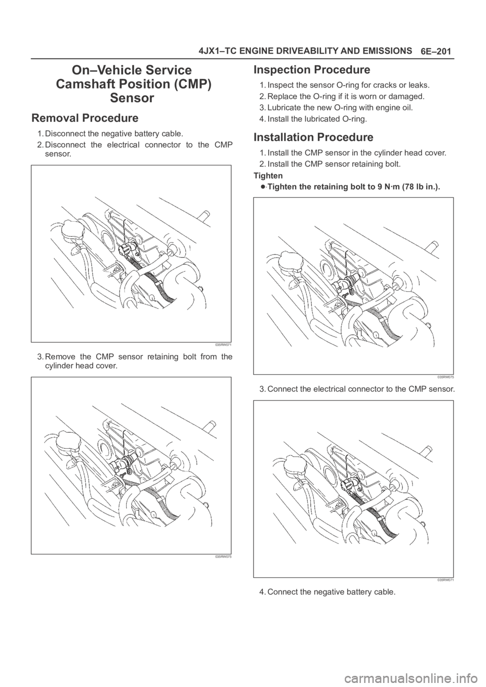
1. Disconnect the negative battery cable.
2. Disconnect the electrical connector to the CMP
sensor.
035RW071
3. Remove the CMP sensor retaining bolt from the
cylinder head cover.
035RW075
Inspection Procedure
1. Inspect the sensor O-ring for cracks or leaks.
2. Replace the O-ring if it is worn or damaged.
3. Lubricate the new O-ring with engine oil.
4. Install the lubricated O-ring.
Installation Procedure
1. Install the CMP sensor in the cylinder head cover.
2. Install the CMP sensor retaining bolt.
Tighten
Tighten the retaining bolt to 9 Nꞏm (78 lb in.).
035RW075
3. Connect the electrical connector to the CMP sensor.
035RW071
4. Connect the negative battery cable.
Page 5631 of 6000
6E–202
4JX1–TC ENGINE DRIVEABILITY AND EMISSIONS
Crankshaft Position (CKP)
Sensor
Removal Procedure
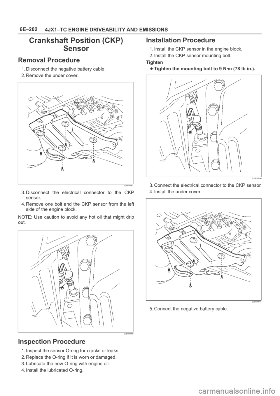
1. Disconnect the negative battery cable.
2. Remove the under cover.
035RW091
3. Disconnect the electrical connector to the CKP
sensor.
4. Remove one bolt and the CKP sensor from the left
side of the engine block.
NOTE: Use caution to avoid any hot oil that might drip
out.
035RW090
Inspection Procedure
1. Inspect the sensor O-ring for cracks or leaks.
2. Replace the O-ring if it is worn or damaged.
3. Lubricate the new O-ring with engine oil.
4. Install the lubricated O-ring.
Installation Procedure
1. Install the CKP sensor in the engine block.
2. Install the CKP sensor mounting bolt.
Tighten
Tighten the mounting bolt to 9 Nꞏm (78 lb in.).
035RW090
3. Connect the electrical connector to the CKP sensor.
4. Install the under cover.
035RW091
5. Connect the negative battery cable.
Page 5636 of 6000
6E–207 4JX1–TC ENGINE DRIVEABILITY AND EMISSIONS
damage, therefore, it is important to use care when
handling and testing electronic components.
NOTE: To prevent possible Electrostatic Discharge
damage, follow these guidelines:
Do not touch the control module connector pins or
soldered components on the control module circuit
board.
Do not open the replacement part package until the
part is ready to be installed.
Before removing the part from the package, ground
the package to a known good ground on the vehicle.
If the part has been handled while sliding across the
seat, or while sitting down from a standing position, or
while walking a distance, touch a known good ground
before installing the part.
NOTE: To prevent internal ECM damage, the ignition
must be in the “OFF” position in order to disconnect or
reconnect power to the ECM (for example: battery cable,
ECM pigtail, ECM fuse, jumper cables, etc.).
IMPORTANT:When replacing the production ECM
with a service ECM, it is important to transfer the
broadcast code and production ECM number to the
service ECM label. This will allow positive identification of
ECM parts throughout the service life of the vehicle. Do
not record this information on the metal ECM cover.
IMPORTANT:The ignition should always be in the
“OFF” position in order to install or remove the ECM
connectors.
Service of the ECM should normally consist of either re-
placement of the ECM. If the diagnostic procedures call
for the ECM to be replaced, the ECM should be checked
first to ensure it is the correct part. If it is, remove the
faulty ECM and install the new service ECM.
DTC P0601 indicates the check sum error.
Removal Procedure
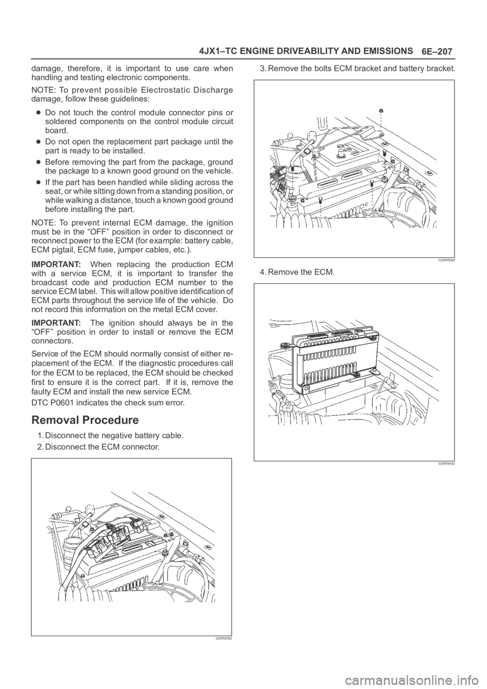
1. Disconnect the negative battery cable.
2. Disconnect the ECM connector.
035RW093
3. Remove the bolts ECM bracket and battery bracket.
035RW094
4. Remove the ECM.
035RW092
Page 5637 of 6000
6E–208
4JX1–TC ENGINE DRIVEABILITY AND EMISSIONS
Installation Procedure
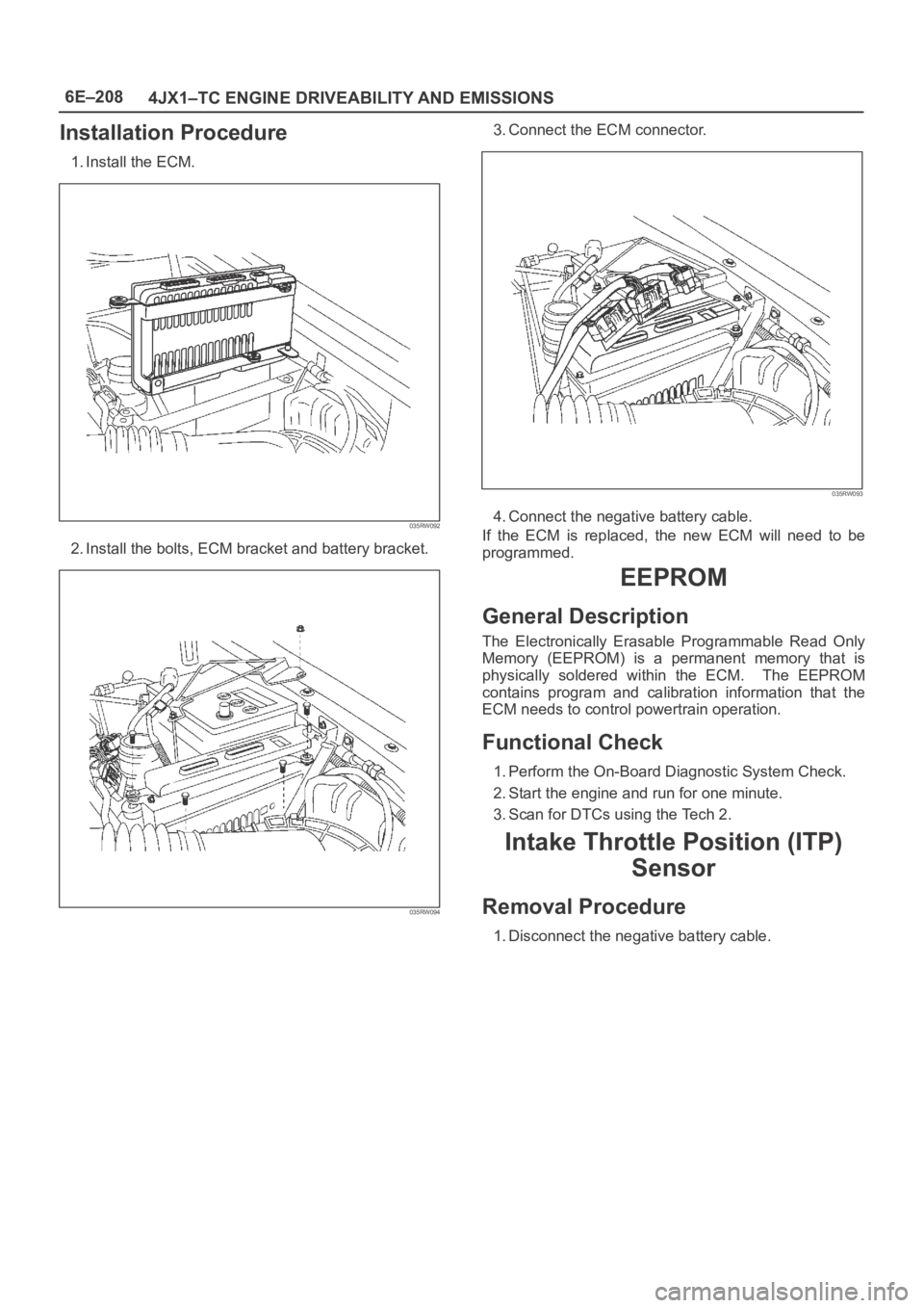
1. Install the ECM.
035RW092
2. Install the bolts, ECM bracket and battery bracket.
035RW094
3. Connect the ECM connector.
035RW093
4. Connect the negative battery cable.
If the ECM is replaced, the new ECM will need to be
programmed.
EEPROM
General Description
The Electronically Erasable Programmable Read Only
Memory (EEPROM) is a permanent memory that is
physically soldered within the ECM. The EEPROM
contains program and calibration information that the
ECM needs to control powertrain operation.
Functional Check
1. Perform the On-Board Diagnostic System Check.
2. Start the engine and run for one minute.
3. Scan for DTCs using the Tech 2.
Intake Throttle Position (ITP)
Sensor
Removal Procedure
1. Disconnect the negative battery cable.
Page 5638 of 6000
6E–209 4JX1–TC ENGINE DRIVEABILITY AND EMISSIONS
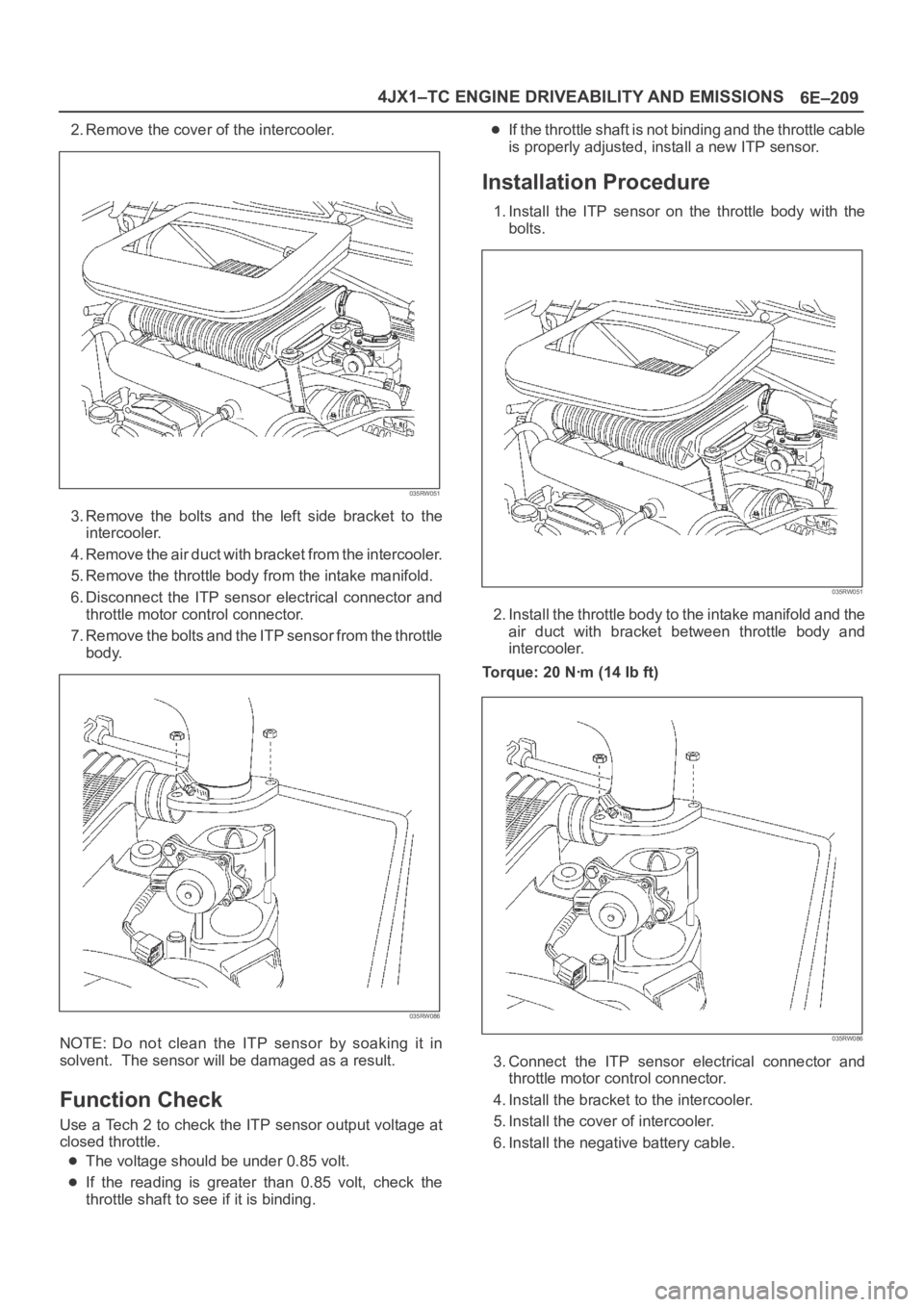
2. Remove the cover of the intercooler.
035RW051
3. Remove the bolts and the left side bracket to the
intercooler.
4 . R e m o v e t h e a i r d u c t w i t h b r a c k e t f r o m t h e i n t e r c o o l e r.
5. Remove the throttle body from the intake manifold.
6. Disconnect the ITP sensor electrical connector and
throttle motor control connector.
7. Remove the bolts and the ITP sensor from the throttle
body.
035RW086
NOTE: Do not clean the ITP sensor by soaking it in
solvent. The sensor will be damaged as a result.
Function Check
Use a Tech 2 to check the ITP sensor output voltage at
closed throttle.
The voltage should be under 0.85 volt.
If the reading is greater than 0.85 volt, check the
throttle shaft to see if it is binding.
If the throttle shaft is not binding and the throttle cable
is properly adjusted, install a new ITP sensor.
Installation Procedure
1. Install the ITP sensor on the throttle body with the
bolts.
035RW051
2. Install the throttle body to the intake manifold and the
air duct with bracket between throttle body and
intercooler.
Torque: 20 Nꞏm (14 Ib ft)
035RW086
3. Connect the ITP sensor electrical connector and
throttle motor control connector.
4. Install the bracket to the intercooler.
5. Install the cover of intercooler.
6. Install the negative battery cable.
Page 5646 of 6000
6E–217 4JX1–TC ENGINE DRIVEABILITY AND EMISSIONS
Throttle Body (TB)
Removal Procedure
1. Disconnect the negative battery cable.
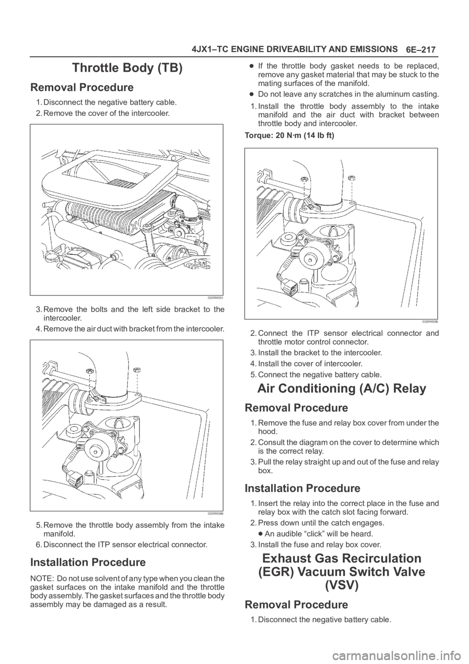
2. Remove the cover of the intercooler.
035RW051
3. Remove the bolts and the left side bracket to the
intercooler.
4 . R e m o v e t h e a i r d u c t w i t h b r a c k e t f r o m t h e i n t e r c o o l e r.
035RW086
5. Remove the throttle body assembly from the intake
manifold.
6. Disconnect the ITP sensor electrical connector.
Installation Procedure
NOTE: Do not use solvent of any type when you clean the
gasket surfaces on the intake manifold and the throttle
body assembly. The gasket surfaces and the throttle body
assembly may be damaged as a result.
If the throttle body gasket needs to be replaced,
remove any gasket material that may be stuck to the
mating surfaces of the manifold.
Do not leave any scratches in the aluminum casting.
1. Install the throttle body assembly to the intake
manifold and the air duct with bracket between
throttle body and intercooler.
Torque: 20 Nꞏm (14 Ib ft)
035RW086
2. Connect the ITP sensor electrical connector and
throttle motor control connector.
3. Install the bracket to the intercooler.
4. Install the cover of intercooler.
5. Connect the negative battery cable.
Air Conditioning (A/C) Relay
Removal Procedure
1. Remove the fuse and relay box cover from under the
hood.
2. Consult the diagram on the cover to determine which
is the correct relay.
3. Pull the relay straight up and out of the fuse and relay
box.
Installation Procedure
1. Insert the relay into the correct place in the fuse and
relay box with the catch slot facing forward.
2. Press down until the catch engages.
An audible “click” will be heard.
3. Install the fuse and relay box cover.
Exhaust Gas Recirculation
(EGR) Vacuum Switch Valve
(VSV)
Removal Procedure
1. Disconnect the negative battery cable.
Page 5647 of 6000
6E–218
4JX1–TC ENGINE DRIVEABILITY AND EMISSIONS
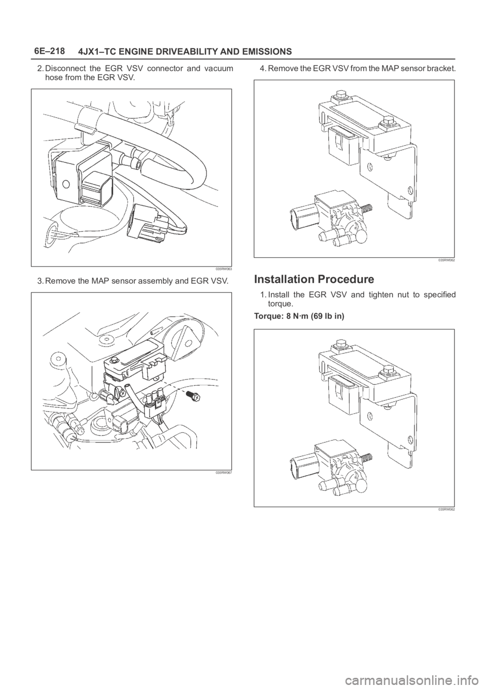
2. Disconnect the EGR VSV connector and vacuum
hose from the EGR VSV.
035RW063
3. Remove the MAP sensor assembly and EGR VSV.
035RW067
4. Remove the EGR VSV from the MAP sensor bracket.
035RW062
Installation Procedure
1. Install the EGR VSV and tighten nut to specified
torque.
Torque: 8 Nꞏm (69 lb in)
035RW062