1998 OPEL FRONTERA rack
[x] Cancel search: rackPage 3974 of 6000
DIFFERENTIAL (REAR 220mm)
4A2A–5
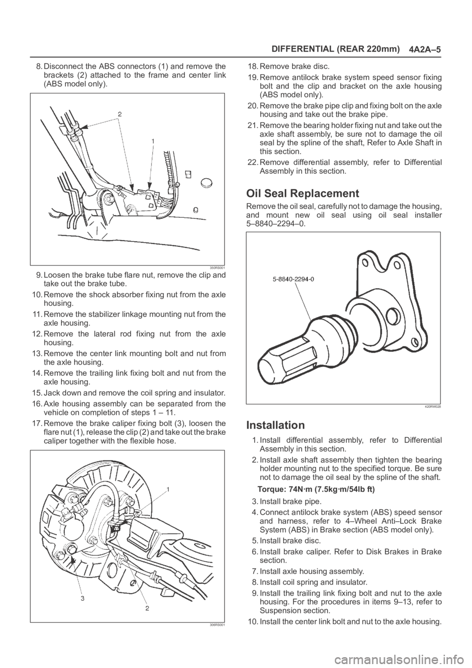
8. Disconnect the ABS connectors (1) and remove the
brackets (2) attached to the frame and center link
(ABS model only).
350RS001
9. Loosen the brake tube flare nut, remove the clip and
take out the brake tube.
10. Remove the shock absorber fixing nut from the axle
housing.
11. Remove the stabilizer linkage mounting nut from the
axle housing.
12. Remove the lateral rod fixing nut from the axle
housing.
13. Remove the center link mounting bolt and nut from
the axle housing.
14. Remove the trailing link fixing bolt and nut from the
axle housing.
15. Jack down and remove the coil spring and insulator.
16. Axle housing assembly can be separated from the
vehicle on completion of steps 1 – 11.
17. Remove the brake caliper fixing bolt (3), loosen the
flare nut (1), release the clip (2) and take out the brake
caliper together with the flexible hose.
306RS001
18. Remove brake disc.
19. Remove antilock brake system speed sensor fixing
bolt and the clip and bracket on the axle housing
(ABS model only).
20. Remove the brake pipe clip and fixing bolt on the axle
housing and take out the brake pipe.
21. Remove the bearing holder fixing nut and take out the
axle shaft assembly, be sure not to damage the oil
seal by the spline of the shaft, Refer to Axle Shaft in
this section.
22. Remove differential assembly, refer to Differential
Assembly in this section.
Oil Seal Replacement
Remove the oil seal, carefully not to damage the housing,
and mount new oil seal using oil seal installer
5–8840–2294–0.
420RW028
Installation
1. Install differential assembly, refer to Differential
Assembly in this section.
2. Install axle shaft assembly then tighten the bearing
holder mounting nut to the specified torque. Be sure
not to damage the oil seal by the spline of the shaft.
Torque: 74Nꞏm (7.5kgꞏm/54lb ft)
3. Install brake pipe.
4. Connect antilock brake system (ABS) speed sensor
and harness, refer to 4–Wheel Anti–Lock Brake
System (ABS) in Brake section (ABS model only).
5. Install brake disc.
6. Install brake caliper. Refer to Disk Brakes in Brake
section.
7. Install axle housing assembly.
8. Install coil spring and insulator.
9. Install the trailing link fixing bolt and nut to the axle
housing. For the procedures in items 9–13, refer to
Suspension section.
10. Install the center link bolt and nut to the axle housing.
Page 3975 of 6000
4A2A–6
DIFFERENTIAL (REAR 220mm)
11. Install the lateral rod fixing nut to the axle housing.
12. Install the stabilizer linkage mounting nut to the axle
housing.
13. Install the shock absorber fixing nut to the axle
housing.
14. Install brake tube flare nut, Refer to Disk Brakes in
Brake section.15. Install ABS connector and bracket (ABS model only).
16. Connect breather hose.
17. Install parking brake cable, Refer to Parking Brakes in
Brake section.
18. Bleed brakes. Refer to Hydraulic Brakes in Brake
section.
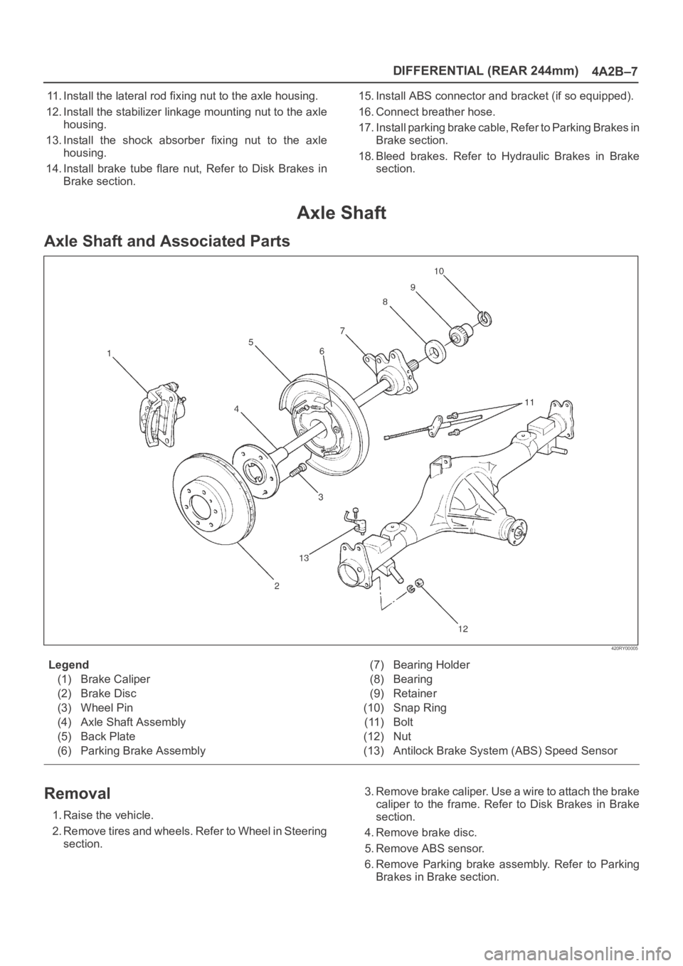
Axle Shaft
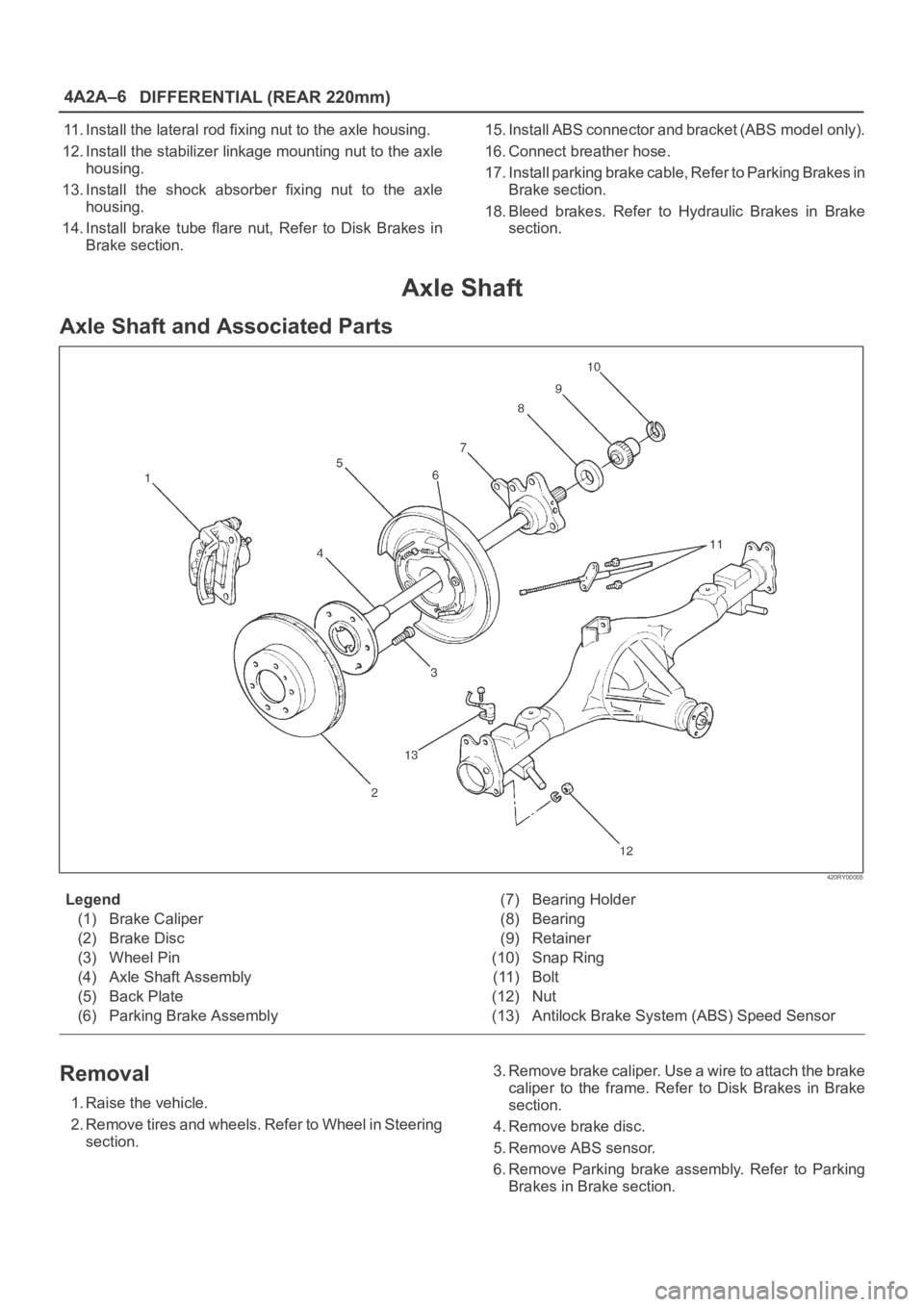
Axle Shaft and Associated Parts
420RY00005
Legend
(1) Brake Caliper
(2) Brake Disc
(3) Wheel Pin
(4) Axle Shaft Assembly
(5) Back Plate
(6) Parking Brake Assembly(7) Bearing Holder
(8) Bearing
(9) Retainer
(10) Snap Ring
(11) Bolt
(12) Nut
(13) Antilock Brake System (ABS) Speed Sensor
Removal
1. Raise the vehicle.
2. Remove tires and wheels. Refer to Wheel in Steering
section.3. Remove brake caliper. Use a wire to attach the brake
caliper to the frame. Refer to Disk Brakes in Brake
section.
4. Remove brake disc.
5. Remove ABS sensor.
6. Remove Parking brake assembly. Refer to Parking
Brakes in Brake section.
Page 4012 of 6000
DIFFERENTIAL (REAR 244mm)
4A2B–5
Axle Housing
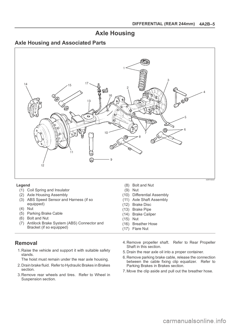
Axle Housing and Associated Parts
420RY00007
Legend
(1) Coil Spring and Insulator
(2) Axle Housing Assembly
(3) ABS Speed Sensor and Harness (if so
equipped)
(4) Nut
(5) Parking Brake Cable
(6) Bolt and Nut
(7) Antilock Brake System (ABS) Connector and
Bracket (if so equipped)(8) Bolt and Nut
(9) Nut
(10) Differential Assembly
(11) Axle Shaft Assembly
(12) Brake Disc
(13) Brake Pipe
(14) Brake Caliper
(15) Nut
(16) Breather Hose
(17) Flare Nut
Removal
1. Raise the vehicle and support it with suitable safety
stands.
The hoist must remain under the rear axle housing.
2. Drain brake fluid. Refer to Hydraulic Brakes in Brakes
section.
3. Remove rear wheels and tires. Refer to Wheel in
Suspension section.4. Remove propeller shaft. Refer to Rear Propeller
Shaft in this section.
5. Drain the rear axle oil into a proper container.
6. Remove parking brake cable, release the connection
between the cable fixing clip equalizer. Refer to
Parking Brakes in Brakes section.
7. Move the clip aside and pull out the breather hose.
Page 4013 of 6000
4A2B–6DIFFERENTIAL (REAR 244mm)
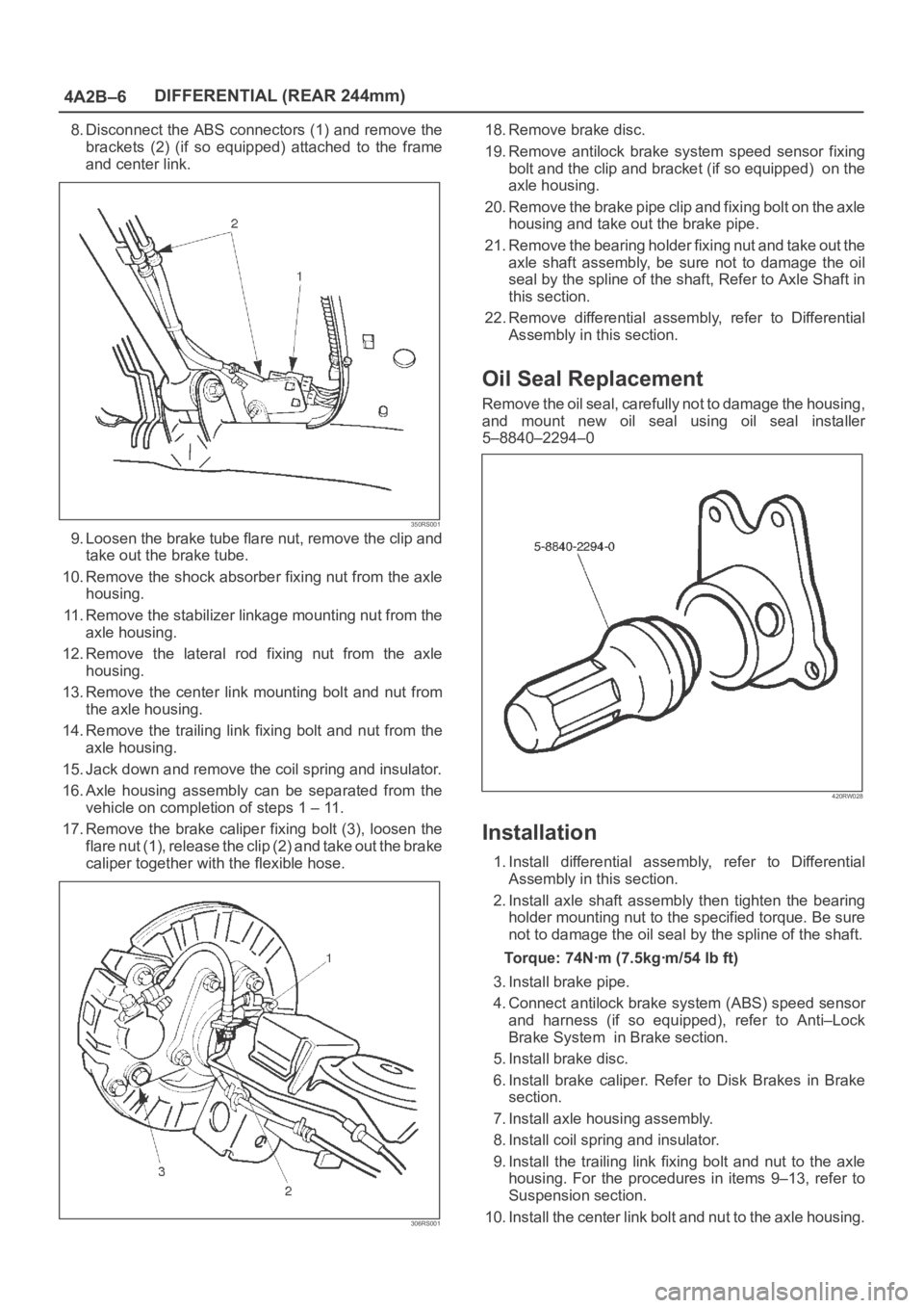
8. Disconnect the ABS connectors (1) and remove the
brackets (2) (if so equipped) attached to the frame
and center link.
350RS001
9. Loosen the brake tube flare nut, remove the clip and
take out the brake tube.
10. Remove the shock absorber fixing nut from the axle
housing.
11. Remove the stabilizer linkage mounting nut from the
axle housing.
12. Remove the lateral rod fixing nut from the axle
housing.
13. Remove the center link mounting bolt and nut from
the axle housing.
14. Remove the trailing link fixing bolt and nut from the
axle housing.
15. Jack down and remove the coil spring and insulator.
16. Axle housing assembly can be separated from the
vehicle on completion of steps 1 – 11.
17. Remove the brake caliper fixing bolt (3), loosen the
flare nut (1), release the clip (2) and take out the brake
caliper together with the flexible hose.
306RS001
18. Remove brake disc.
19. Remove antilock brake system speed sensor fixing
bolt and the clip and bracket (if so equipped) on the
axle housing.
20. Remove the brake pipe clip and fixing bolt on the axle
housing and take out the brake pipe.
21. Remove the bearing holder fixing nut and take out the
axle shaft assembly, be sure not to damage the oil
seal by the spline of the shaft, Refer to Axle Shaft in
this section.
22. Remove differential assembly, refer to Differential
Assembly in this section.
Oil Seal Replacement
Remove the oil seal, carefully not to damage the housing,
and mount new oil seal using oil seal installer
5–8840–2294–0
420RW028
Installation
1. Install differential assembly, refer to Differential
Assembly in this section.
2. Install axle shaft assembly then tighten the bearing
holder mounting nut to the specified torque. Be sure
not to damage the oil seal by the spline of the shaft.
Torque: 74Nꞏm (7.5kgꞏm/54 lb ft)
3. Install brake pipe.
4. Connect antilock brake system (ABS) speed sensor
and harness (if so equipped), refer to Anti–Lock
Brake System in Brake section.
5. Install brake disc.
6. Install brake caliper. Refer to Disk Brakes in Brake
section.
7. Install axle housing assembly.
8. Install coil spring and insulator.
9. Install the trailing link fixing bolt and nut to the axle
housing. For the procedures in items 9–13, refer to
Suspension section.
10. Install the center link bolt and nut to the axle housing.
Page 4014 of 6000
DIFFERENTIAL (REAR 244mm)
4A2B–7
11. Install the lateral rod fixing nut to the axle housing.
12. Install the stabilizer linkage mounting nut to the axle
housing.
13. Install the shock absorber fixing nut to the axle
housing.
14. Install brake tube flare nut, Refer to Disk Brakes in
Brake section.15. Install ABS connector and bracket (if so equipped).
16. Connect breather hose.
17. Install parking brake cable, Refer to Parking Brakes in
Brake section.
18. Bleed brakes. Refer to Hydraulic Brakes in Brake
section.
Axle Shaft
Axle Shaft and Associated Parts
420RY00005
Legend
(1) Brake Caliper
(2) Brake Disc
(3) Wheel Pin
(4) Axle Shaft Assembly
(5) Back Plate
(6) Parking Brake Assembly(7) Bearing Holder
(8) Bearing
(9) Retainer
(10) Snap Ring
(11) Bolt
(12) Nut
(13) Antilock Brake System (ABS) Speed Sensor
Removal
1. Raise the vehicle.
2. Remove tires and wheels. Refer to Wheel in Steering
section.3. Remove brake caliper. Use a wire to attach the brake
caliper to the frame. Refer to Disk Brakes in Brake
section.
4. Remove brake disc.
5. Remove ABS sensor.
6. Remove Parking brake assembly. Refer to Parking
Brakes in Brake section.
Page 4090 of 6000
4B2–7 DRIVE LINE CONTROL SYSTEM (TOD)
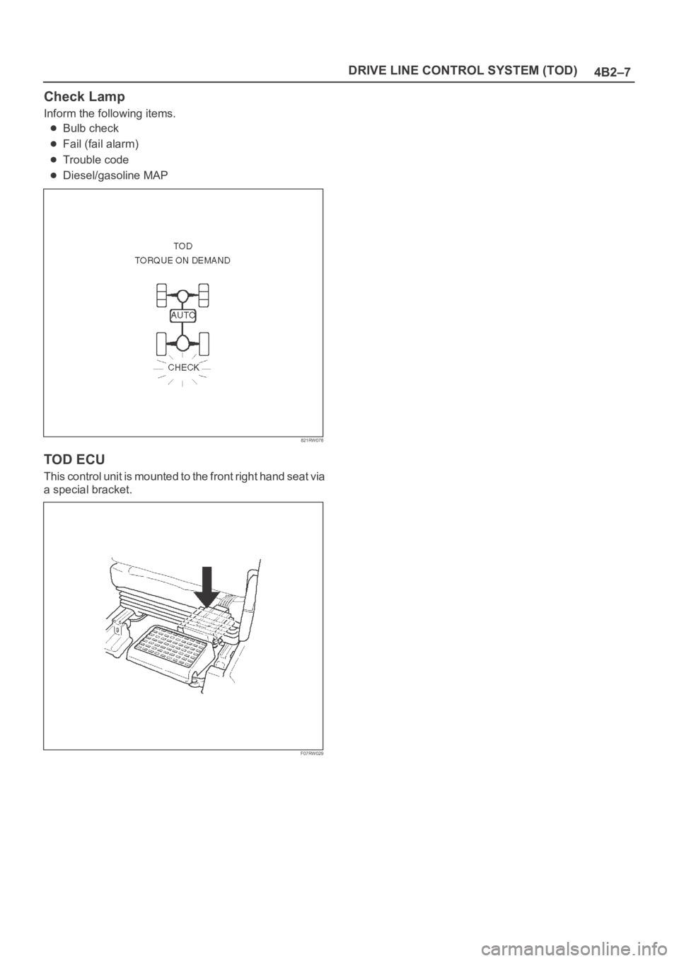
Check Lamp
Inform the following items.
Bulb check
Fail (fail alarm)
Trouble code
Diesel/gasoline MAP
821RW078
TOD ECU
This control unit is mounted to the front right hand seat via
a special bracket.
F07RW029
Page 4209 of 6000
4C–3 DRIVE SHAFT SYSTEM
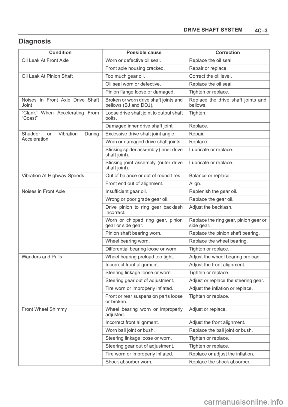
Diagnosis
ConditionPossible causeCorrection
Oil Leak At Front AxleWorn or defective oil seal.Replace the oil seal.
Front axle housing cracked.Repair or replace.
Oil Leak At Pinion ShaftToo much gear oil.Correct the oil level.
Oil seal worn or defective.Replace the oil seal.
Pinion flange loose or damaged.Tighten or replace.
Noises In Front Axle Drive Shaft
JointBroken or worn drive shaft joints and
bellows (BJ and DOJ).Replace the drive shaft joints and
bellows.
“Clank” When Accelerating From
“Coast”Loose drive shaft joint to output shaft
bolts.Tighten.
Damaged inner drive shaft joint.Replace.
Shudder or Vibration During
Acceleration
Excessive drive shaft joint angle.Repair.
AccelerationWorn or damaged drive shaft joints.Replace.
Sticking spider assembly (inner drive
shaft joint).Lubricate or replace.
Sticking joint assembly (outer drive
shaft joint).Lubricate or replace.
Vibration At Highway SpeedsOut of balance or out of round tires.Balance or replace.
Front end out of alignment.Align.
Noises in Front AxleInsufficient gear oil.Replenish the gear oil.
Wrong or poor grade gear oil.Replace the gear oil.
Drive pinion to ring gear backlash
incorrect.Adjust the backlash.
Worn or chipped ring gear, pinion
gear or side gear.Replace the ring gear, pinion gear or
side gear.
Pinion shaft bearing worn.Replace the pinion shaft bearing.
Wheel bearing worn.Replace the wheel bearing.
Differential bearing loose or worn.Tighten or replace.
Wanders and PullsWheel bearing preload too tight.Adjust the wheel bearing preload.
Incorrect front alignment.Adjust the front alignment.
Steering linkage loose or worn.Tighten or replace.
Steering gear out of adjustment.Adjust or replace the steering gear.
Tire worn or improperly inflated.Adjust the inflation or replace.
Front or rear suspension parts loose
or broken.Tighten or replace.
Front Wheel ShimmyWheel bearing worn or improperly
adjusted.Adjust or replace.
Incorrect front alignment.Adjust the front alignment.
Worn ball joint or bush.Replace the ball joint or bush.
Steering linkage loose or worn.Tighten or replace.
Steering gear out of adjustment.Tighten or replace.
Tire worn or improperly inflated.Replace or adjust the inflation.
Shock absorber worn.Replace the shock absorber.
Page 4229 of 6000
4C–23 DRIVE SHAFT SYSTEM
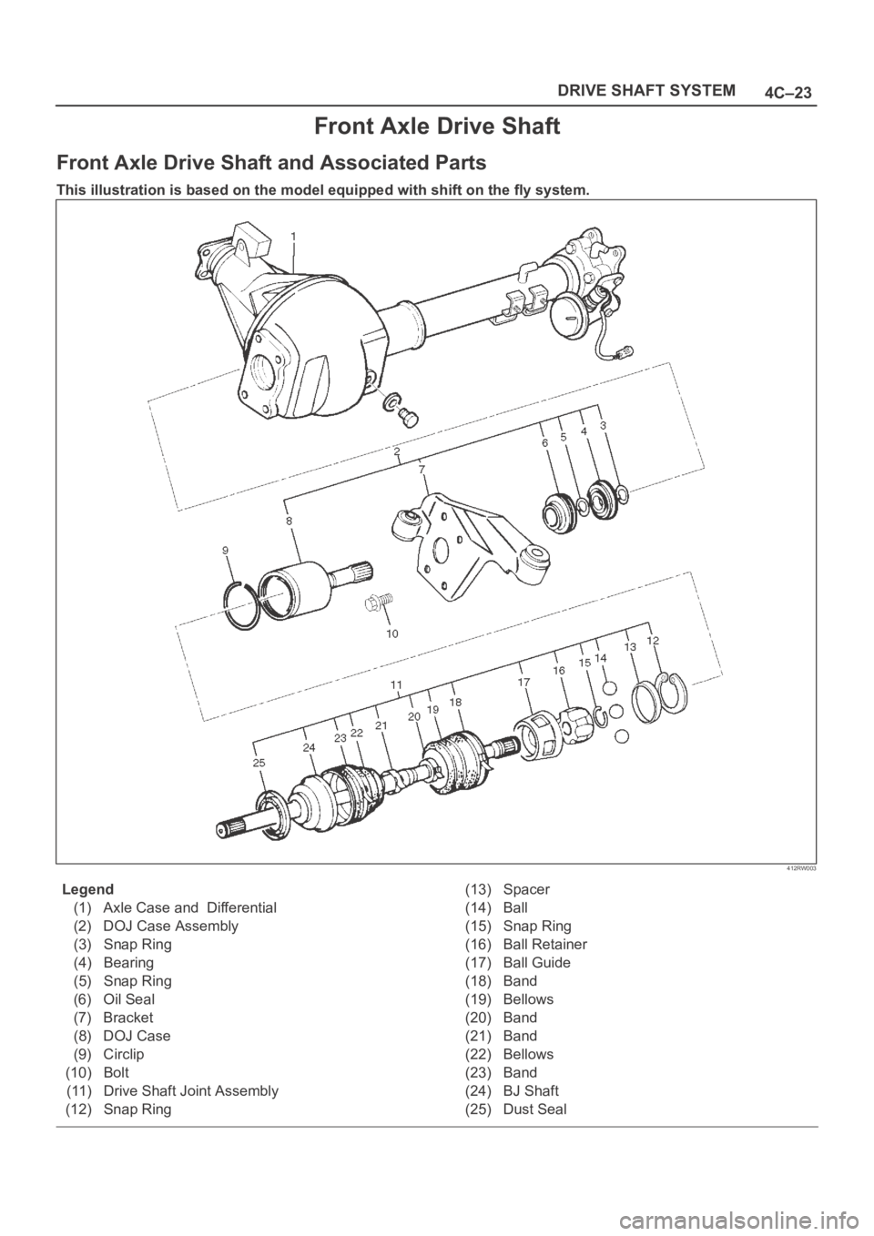
Front Axle Drive Shaft
Front Axle Drive Shaft and Associated Parts
This illustration is based on the model equipped with shift on the fly system.
412RW003
Legend
(1) Axle Case and Differential
(2) DOJ Case Assembly
(3) Snap Ring
(4) Bearing
(5) Snap Ring
(6) Oil Seal
(7) Bracket
(8) DOJ Case
(9) Circlip
(10) Bolt
(11) Drive Shaft Joint Assembly
(12) Snap Ring(13) Spacer
(14) Ball
(15) Snap Ring
(16) Ball Retainer
(17) Ball Guide
(18) Band
(19) Bellows
(20) Band
(21) Band
(22) Bellows
(23) Band
(24) BJ Shaft
(25) Dust Seal