1998 OPEL FRONTERA rack
[x] Cancel search: rackPage 3781 of 6000
COMPRESSOR SHAFT SEAL
Service Precaution
When replacing the shaft seal assembly, pressure relief
valve or control switches, it will be necessary to recover
the refrigerant. Other than clutch repair procedures, the
same holds true for any disassembly of the compressor.
A clean workbench covered with a sheet of clean
paper, and a place (clean trays, etc) for all parts being
removed and replaced is important, as is the use of
proper clean service tools.
CAUTION: Any attempt to use makeshift or
inadequate service tools or equipment may result
in damage and/or improper compressor operation.
All parts required for servicing the internal compressor
are protected by a preservative process and packaged
in a manner which will eliminate the necessity of
cleaning, washing or flushing of the parts. The parts
can be used in the internal assembly just as they are
removed from the service package. Seals and
protective packaging should be left intact until just
prior to installation.
If the compressor rear head, front head or cylinder and
shaft assembly is to be serviced or replaced, the oil in
the compressor must be drained, measured, recorded
and replaced.
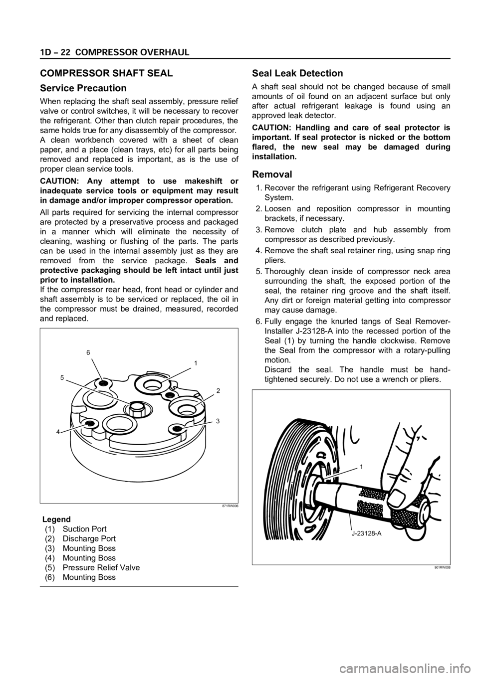
Legend
(1) Suction Port
(2) Discharge Port
(3) Mounting Boss
(4) Mounting Boss
(5) Pressure Relief Valve
(6) Mounting Boss
Seal Leak Detection
A shaft seal should not be changed because of small
amounts of oil found on an adjacent surface but only
after actual refrigerant leakage is found using an
approved leak detector.
CAUTION: Handling and care of seal protector is
important. If seal protector is nicked or the bottom
flared, the new seal may be damaged during
installation.
Removal
1. Recover the refrigerant using Refrigerant Recovery
System.
2. Loosen and reposition compressor in mounting
brackets, if necessary.
3. Remove clutch plate and hub assembly from
compressor as described previously.
4. Remove the shaft seal retainer ring, using snap ring
pliers.
5. Thoroughly clean inside of compressor neck area
surrounding the shaft, the exposed portion of the
seal, the retainer ring groove and the shaft itself.
Any dirt or foreign material getting into compressor
may cause damage.
6. Fully engage the knurled tangs of Seal Remover-
Installer J-23128-A into the recessed portion of the
Seal (1) by turning the handle clockwise. Remove
the Seal from the compressor with a rotary-pulling
motion.
Discard the seal. The handle must be hand-
tightened securely. Do not use a wrench or pliers.
1
2
3
456
871RW006
J-23128-A1
901RW008
Page 3783 of 6000

6. Remove any excess oil resulting from installing the
new seal parts from the shaft and inside the
compressor neck.
7. Install the clutch plate and hub assembly as
described previously.8. Reinstall compressor belt and tighten bracket.
9. Evacuate and charge the refrigerant system.
COMPRESSOR PRESSURE RELIEF VALVE
Removal
1. Recover the refrigerant using Refrigerant Recovery
System.
2. Remove old pressure relief valve.
Installation
1. Clean valve seat area on rear head.2. Lubricate O-ring of new pressure relief valve and
O-ring assembly with new 525 viscosity refrigerant
oil. Install new valve and torque in place, 9.0 Nꞏm
(6.1 ft lbs)
3. Evacuate and recharge the system.
4. Leak test system.
COMPRESSOR OIL
Compressor Oil Check
The oil used to lubricate the compressor is circulating
with the refrigerant.
Whenever replacing any component of the system or a
large amount of gas leakage occurs, add oil to maintain
the original amount of oil.
Checking and Adjusting Oil Quantity for
Used Compressor
1. Perform oil return operation. Refer to Oil Return
Operation in this section.
2. Discharge and recover refrigerant and remove the
compressor.
3. Drain the compressor oil and measure the extracted
oil with a measuring cylinder.
4. If the amount of oil drained is much less than 90 cc
(3.0 fl. oz.), some refrigerant may have leaked out.
Conduct a leak tests on the connections of each
system, and if necessary, repair or replace faulty
parts.
5. Check the compressor oil contamination. (Refer to
Contamination of Compressor Oil in this section.)
6. Adjust the oil level following the next procedure
below.7. Install the compressor, then evacuate, charge and
perform the oil return operation.
8. Check system operation.
When it is impossible to preform oil return
operation, the compressor oil should be checked in
the following order:
1. Discharge and recover refrigerant and remove the
compressor.
2. Drain the compressor oil and measure the extracted
oil with a measuring cylinder.
3. Check the oil for contamination.
4. If more than 90 cc (3.0 fl. oz.) of oil is extracted from
the compressor, supply the same amount of oil to
the compressor to be installed. If the amount of oil
extracted is less than 90 cc (3.0 fl. oz.), recheck the
compressor oil in the following order:
5. Supply 90 cc (3.0 fl. oz.) of oil to the compressor
and install it onto the vehicle.
6. Evacuate and recharge with the proper amount of
refrigerant.
7. Perform the oil return operation.
8. Remove the compressor and recheck the amount of
oil.
9. Adjust the compressor oil, if necessary.
Checking and Adjusting for Compressor
Replacement
The oil is not charged in compressor (service parts). So
it is necessary to charge the proper amount of oil to the
new compressor. (Oil Capacity)
Capacity total in system 150 cc (5.0 fl.oz)
Compressor (Service 150 cc (5.0 fl.oz)
parts) charging amount
(Collected Amount) (Charging Amount)
more than 90 cc same as collected
(3.0 fl.oz) amount
less than 90 cc (3.0 fl.oz) 90 cc (3.0 fl.oz)
(Collected Amount) (Charging Amount)
more than 90 cc same as collected
(3.0 fl.oz) amount
less than 90 cc (3.0 fl.oz) 90 cc (3.0 fl.oz)
Page 3942 of 6000
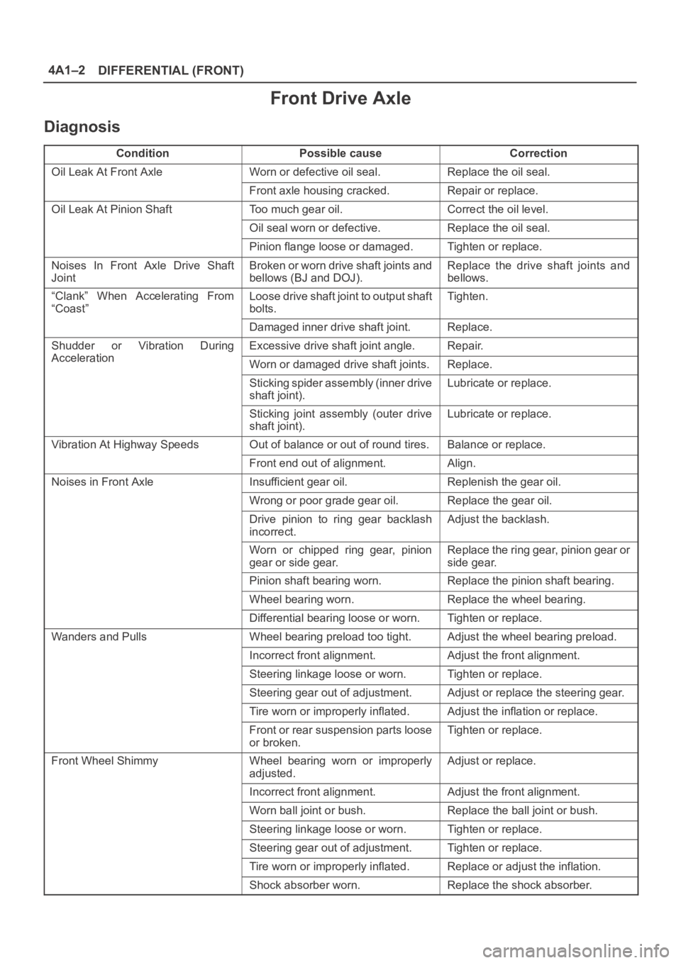
DIFFERENTIAL (FRONT) 4A1–2
Front Drive Axle
Diagnosis
ConditionPossible causeCorrection
Oil Leak At Front AxleWorn or defective oil seal.Replace the oil seal.
Front axle housing cracked.Repair or replace.
Oil Leak At Pinion ShaftToo much gear oil.Correct the oil level.
Oil seal worn or defective.Replace the oil seal.
Pinion flange loose or damaged.Tighten or replace.
Noises In Front Axle Drive Shaft
JointBroken or worn drive shaft joints and
bellows (BJ and DOJ).Replace the drive shaft joints and
bellows.
“Clank” When Accelerating From
“Coast”Loose drive shaft joint to output shaft
bolts.Tighten.
Damaged inner drive shaft joint.Replace.
Shudder or Vibration During
Acceleration
Excessive drive shaft joint angle.Repair.
AccelerationWorn or damaged drive shaft joints.Replace.
Sticking spider assembly (inner drive
shaft joint).Lubricate or replace.
Sticking joint assembly (outer drive
shaft joint).Lubricate or replace.
Vibration At Highway SpeedsOut of balance or out of round tires.Balance or replace.
Front end out of alignment.Align.
Noises in Front AxleInsufficient gear oil.Replenish the gear oil.
Wrong or poor grade gear oil.Replace the gear oil.
Drive pinion to ring gear backlash
incorrect.Adjust the backlash.
Worn or chipped ring gear, pinion
gear or side gear.Replace the ring gear, pinion gear or
side gear.
Pinion shaft bearing worn.Replace the pinion shaft bearing.
Wheel bearing worn.Replace the wheel bearing.
Differential bearing loose or worn.Tighten or replace.
Wanders and PullsWheel bearing preload too tight.Adjust the wheel bearing preload.
Incorrect front alignment.Adjust the front alignment.
Steering linkage loose or worn.Tighten or replace.
Steering gear out of adjustment.Adjust or replace the steering gear.
Tire worn or improperly inflated.Adjust the inflation or replace.
Front or rear suspension parts loose
or broken.Tighten or replace.
Front Wheel ShimmyWheel bearing worn or improperly
adjusted.Adjust or replace.
Incorrect front alignment.Adjust the front alignment.
Worn ball joint or bush.Replace the ball joint or bush.
Steering linkage loose or worn.Tighten or replace.
Steering gear out of adjustment.Tighten or replace.
Tire worn or improperly inflated.Replace or adjust the inflation.
Shock absorber worn.Replace the shock absorber.
Page 3947 of 6000
4A1–7 DIFFERENTIAL (FRONT)
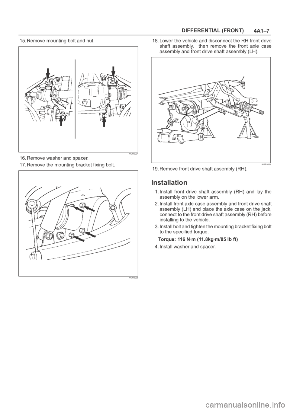
15. Remove mounting bolt and nut.
412RS004
16. Remove washer and spacer.
17. Remove the mounting bracket fixing bolt.
412RS005
18. Lower the vehicle and disconnect the RH front drive
shaft assembly, then remove the front axle case
assembly and front drive shaft assembly (LH).
412RS006
19. Remove front drive shaft assembly (RH).
Installation
1. Install front drive shaft assembly (RH) and lay the
assembly on the lower arm.
2. Install front axle case assembly and front drive shaft
assembly (LH) and place the axle case on the jack,
connect to the front drive shaft assembly (RH) before
installing to the vehicle.
3. Install bolt and tighten the mounting bracket fixing bolt
to the specified torque.
Torque: 116 Nꞏm (11.8kgꞏm/85 lb ft)
4. Install washer and spacer.
Page 3949 of 6000
4A1–9 DIFFERENTIAL (FRONT)
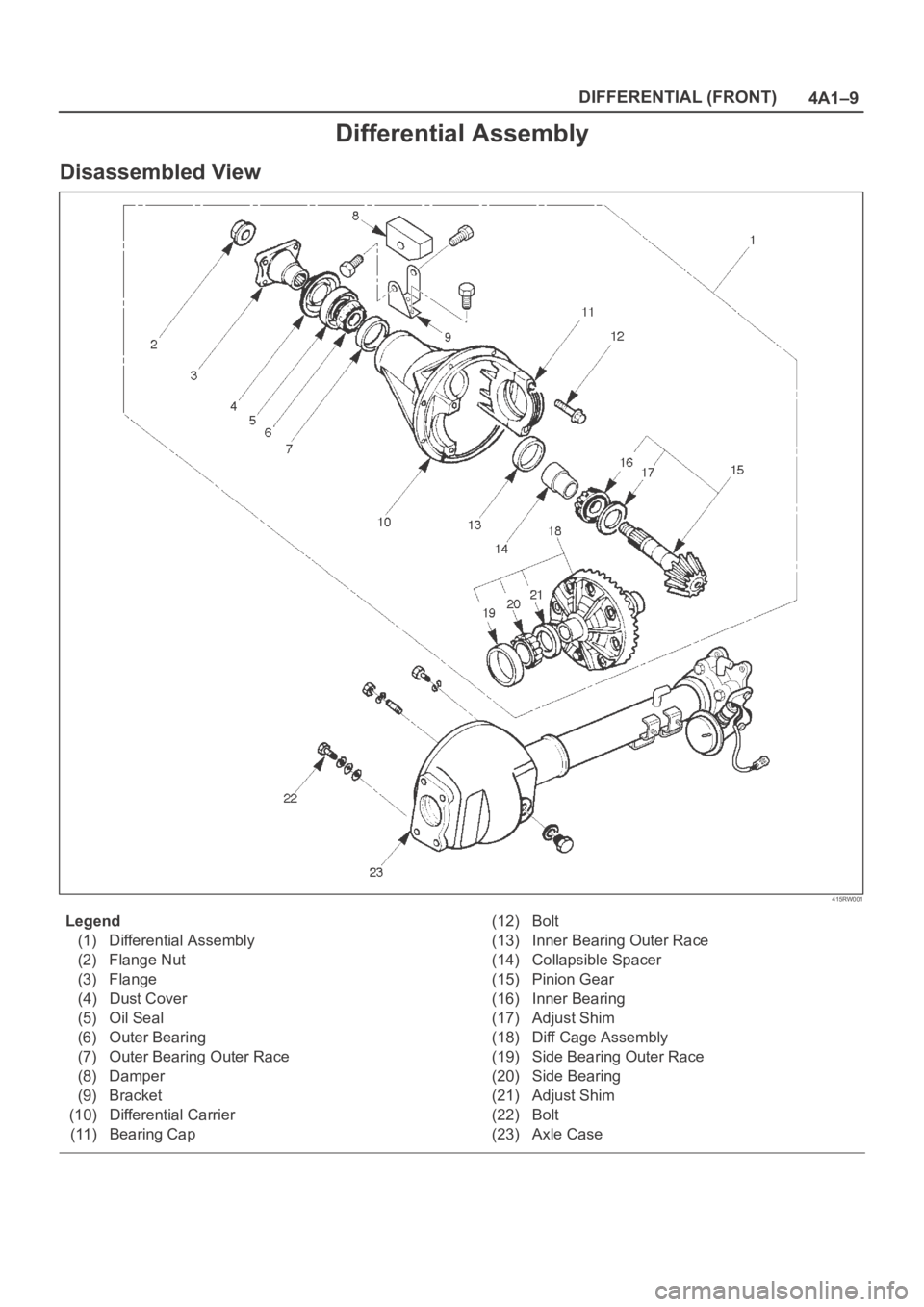
Differential Assembly
Disassembled View
415RW001
Legend
(1) Differential Assembly
(2) Flange Nut
(3) Flange
(4) Dust Cover
(5) Oil Seal
(6) Outer Bearing
(7) Outer Bearing Outer Race
(8) Damper
(9) Bracket
(10) Differential Carrier
(11) Bearing Cap(12) Bolt
(13) Inner Bearing Outer Race
(14) Collapsible Spacer
(15) Pinion Gear
(16) Inner Bearing
(17) Adjust Shim
(18) Diff Cage Assembly
(19) Side Bearing Outer Race
(20) Side Bearing
(21) Adjust Shim
(22) Bolt
(23) Axle Case
Page 3952 of 6000
DIFFERENTIAL (FRONT) 4A1–12
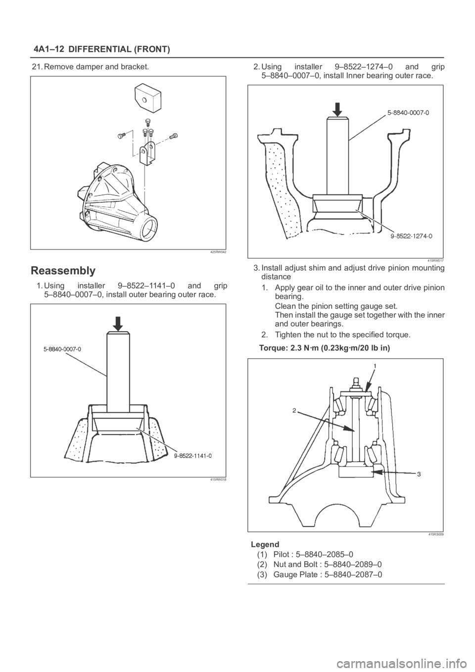
21. Remove damper and bracket.
425RW042
Reassembly
1. Using installer 9–8522–1141–0 and grip
5–8840–0007–0, install outer bearing outer race.
415RW018
2. Using installer 9–8522–1274–0 and grip
5–8840–0007–0, install Inner bearing outer race.
415RW017
3. Install adjust shim and adjust drive pinion mounting
distance
1. Apply gear oil to the inner and outer drive pinion
bearing.
Clean the pinion setting gauge set.
Then install the gauge set together with the inner
and outer bearings.
2. Tighten the nut to the specified torque.
Torque: 2.3 Nꞏm (0.23kgꞏm/20 lb in)
415RS009
Legend
(1) Pilot : 5–8840–2085–0
(2) Nut and Bolt : 5–8840–2089–0
(3) Gauge Plate : 5–8840–2087–0
Page 3960 of 6000
DIFFERENTIAL (FRONT) 4A1–20
425RS039
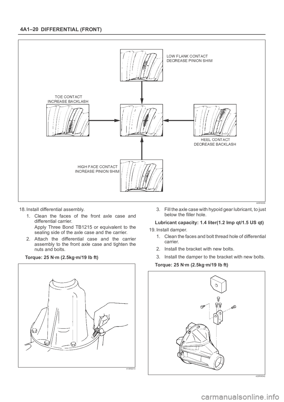
18. Install differential assembly.
1. Clean the faces of the front axle case and
differential carrier.
Apply Three Bond TB1215 or equivalent to the
sealing side of the axle case and the carrier.
2. Attach the differential case and the carrier
assembly to the front axle case and tighten the
nuts and bolts.
To r q u e : 2 5 N ꞏm ( 2 . 5 k g ꞏm / 1 9 l b f t )
415RS014
3. Fill the axle case with hypoid gear lubricant, to just
below the filler hole.
Lubricant capacity: 1.4 liter(1.2 Imp qt/1.5 US qt)
19. Install damper.
1. Clean the faces and bolt thread hole of differential
carrier.
2. Install the bracket with new bolts.
3. Install the damper to the bracket with new bolts.
Torque: 25 Nꞏm (2.5kgꞏm/19 lb ft)
425RW042
Page 3973 of 6000
4A2A–4
DIFFERENTIAL (REAR 220mm)
Axle Housing
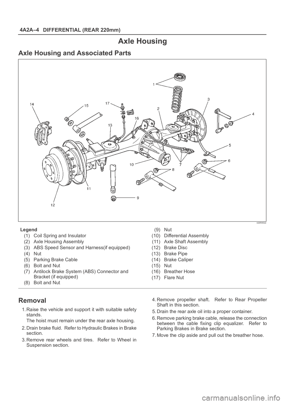
Axle Housing and Associated Parts
420RW022
Legend
(1) Coil Spring and Insulator
(2) Axle Housing Assembly
(3) ABS Speed Sensor and Harness(if equipped)
(4) Nut
(5) Parking Brake Cable
(6) Bolt and Nut
(7) Antilock Brake System (ABS) Connector and
Bracket (if equipped)
(8) Bolt and Nut(9) Nut
(10) Differential Assembly
(11) Axle Shaft Assembly
(12) Brake Disc
(13) Brake Pipe
(14) Brake Caliper
(15) Nut
(16) Breather Hose
(17) Flare Nut
Removal
1. Raise the vehicle and support it with suitable safety
stands.
The hoist must remain under the rear axle housing.
2. Drain brake fluid. Refer to Hydraulic Brakes in Brake
section.
3. Remove rear wheels and tires. Refer to Wheel in
Suspension section.4. Remove propeller shaft. Refer to Rear Propeller
Shaft in this section.
5. Drain the rear axle oil into a proper container.
6. Remove parking brake cable, release the connection
between the cable fixing clip equalizer. Refer to
Parking Brakes in Brake section.
7. Move the clip aside and pull out the breather hose.