Page 3334 of 6000
8G–22SEATS
Disassembly (Bench Type)
1. Remove the device cover.
2. Remove the release knob.
Turn the knob to the counterclockwise to remove it.
3. Remove the release rod.
Disconnect the rod from the linkage bush.
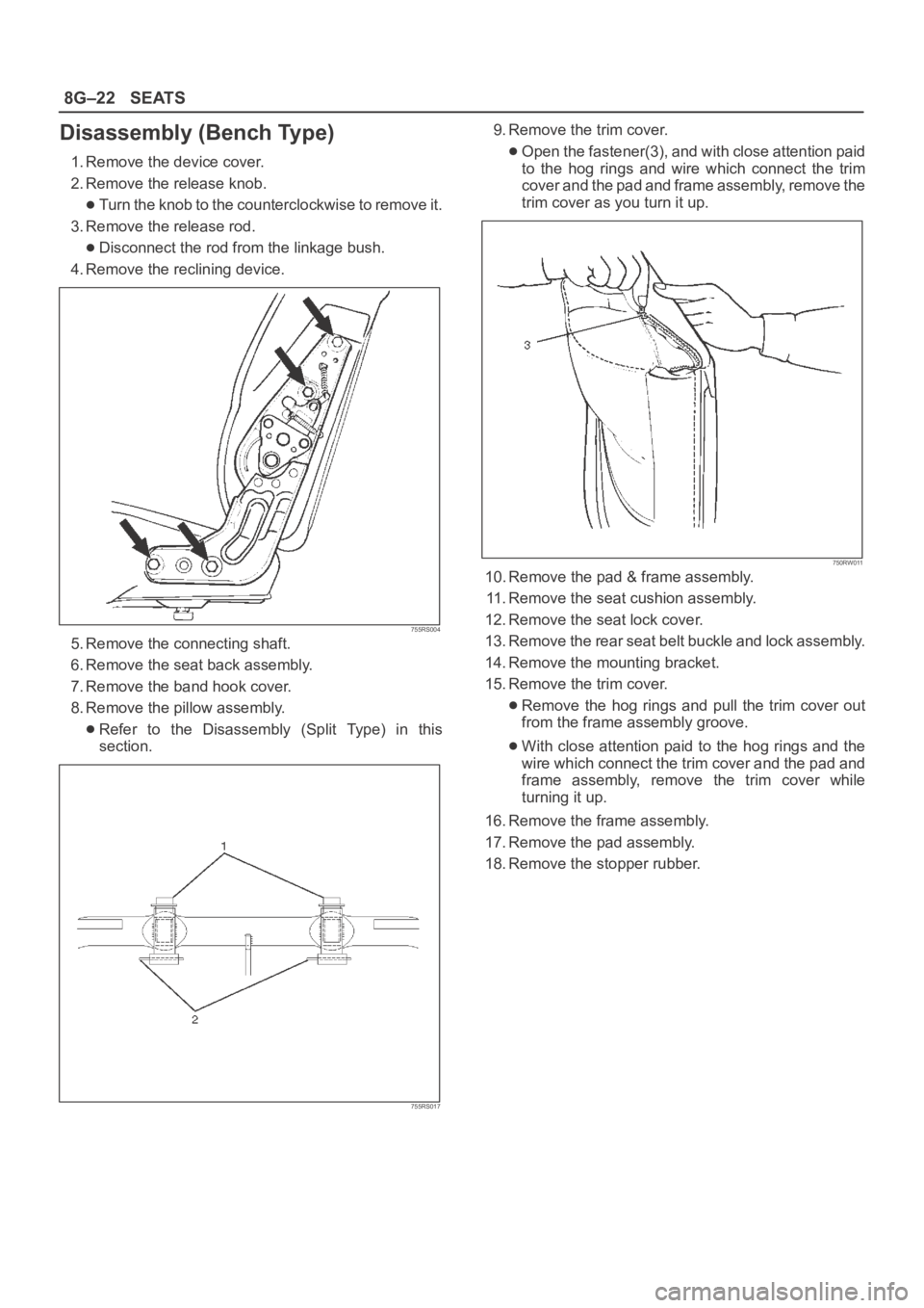
4. Remove the reclining device.
755RS004
5. Remove the connecting shaft.
6. Remove the seat back assembly.
7. Remove the band hook cover.
8. Remove the pillow assembly.
Refer to the Disassembly (Split Type) in this
section.
755RS017
9. Remove the trim cover.
Open the fastener(3), and with close attention paid
to the hog rings and wire which connect the trim
cover and the pad and frame assembly, remove the
trim cover as you turn it up.
750RW011
10. Remove the pad & frame assembly.
11. Remove the seat cushion assembly.
12. Remove the seat lock cover.
13. Remove the rear seat belt buckle and lock assembly.
14. Remove the mounting bracket.
15. Remove the trim cover.
Remove the hog rings and pull the trim cover out
from the frame assembly groove.
With close attention paid to the hog rings and the
wire which connect the trim cover and the pad and
frame assembly, remove the trim cover while
turning it up.
16. Remove the frame assembly.
17. Remove the pad assembly.
18. Remove the stopper rubber.
Page 3336 of 6000
8G–24SEATS
Installation
To reassemble, follow the disassembly steps in the
reverse order, noting the following point.1. Tighten the reclining device fixing bolts to the
specified torque.
Torque: 19 Nꞏm (1.9kgꞏm/14 lb ft)
Disassembled View
755RW035
Legend
(1) Seat Back Assembly
(2) Pad & Frame Assembly
(3) Trim Cover
(4) Hinge Knob
(5) Hinge Cover
(6) Hinge Assembly
(7) Trim Cover
(8) Arm Bracket
(9) Bush
(10) Bracket
(11) Arm Bracket Cover
(12) Pad & Frame Assembly
(13) Seat Cushion Assembly(14) Board Assembly
(15) E–Ring
(16) Cam Bracket
(17) Tension Spring
(18) Leg Pipe Assembly
(19) Hing Pin
(20) Lock Cover
(21) Floor Lock Assembly
(22) Lock Cover
(23) Band Assembly
(24) Arm Bracket
(25) Free Hinge
(26) Free Hinge Bolt
Page 3337 of 6000
SEATS8G–25
Disassembly
1. Remove the hinge knob.
Pull the knob out from hinge assembly.
2. Remove the hinge cover.
3. Remove the hinge assembly.
4. Remove the free hinge bolt.
5. Remove the seat back assembly.
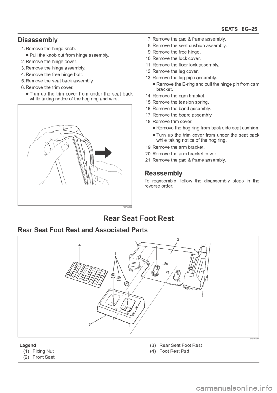
6. Remove the trim cover.
Trun up the trim cover from under the seat back
while taking notice of the hog ring and wire.
755RW032
7. Remove the pad & frame assembly.
8. Remove the seat cushion assembly.
9. Remove the free hinge.
10. Remove the lock cover.
11. Remove the floor lock assembly.
12. Remove the leg cover.
13. Remove the leg pipe assembly.
Remove the E-ring and pull the hinge pin from cam
bracket.
14. Remove the cam bracket.
15. Remove the tension spring.
16. Remove the band assembly.
17. Remove the board assembly.
18. Remove trim cover.
Remove the hog ring from back side seat cushion.
Turn up the trim cover from under the seat back
while taking notice of the hog ring.
19. Remove the arm bracket.
20. Remove the arm bracket cover.
21. Remove the pad & frame assembly.
Reassembly
To reassemble, follow the disassembly steps in the
reverse order.
Rear Seat Foot Rest
Rear Seat Foot Rest and Associated Parts
676RS001
Legend
(1) Fixing Nut
(2) Front Seat(3) Rear Seat Foot Rest
(4) Foot Rest Pad
Page 3361 of 6000
8H–22SECURITY AND LOCKS
Anti-theft System
General Description
The circuit consists of the starter switch, anti-theft &
keyless entry control unit, anti-theft horn, front door and
tailgate key switch (detect and tamper switch), door lock
(& power window) switch, door lock actuator for each
door, engine hood switch, clutch start switch (M/T),
ANTI-THEFT indicator light and mode switch (A/T).
The system operates as follows: After locking the starter
switch and removing the starter key (this sets the alarm),
if the door is unlocked in any way other than with the
proper key, the headlights start flashing, the horn sounds,
and the starter circuit is disabled. (However, the engine
hood and all the doors must be locked and closed.)
Once the system has been placed in the warning or alarm
condition, it can be released only when the starter switch
is shifted from “OFF” to “ACC” by the starter key, or when
the lock of the front door or the tailgate is released (to
activate the detect switch) by the starter key.
Anti-theft & Keyless Entry Control
Unit Removal
1. Disconnect the battery ground cable.
2. Remove the front console assembly.
Refer to the Instrument Panel Assembly in Body
Structure section.
3. Remove the lower cluster assembly.
Refer to the Instrument Panel Assembly in Body
Structure section.
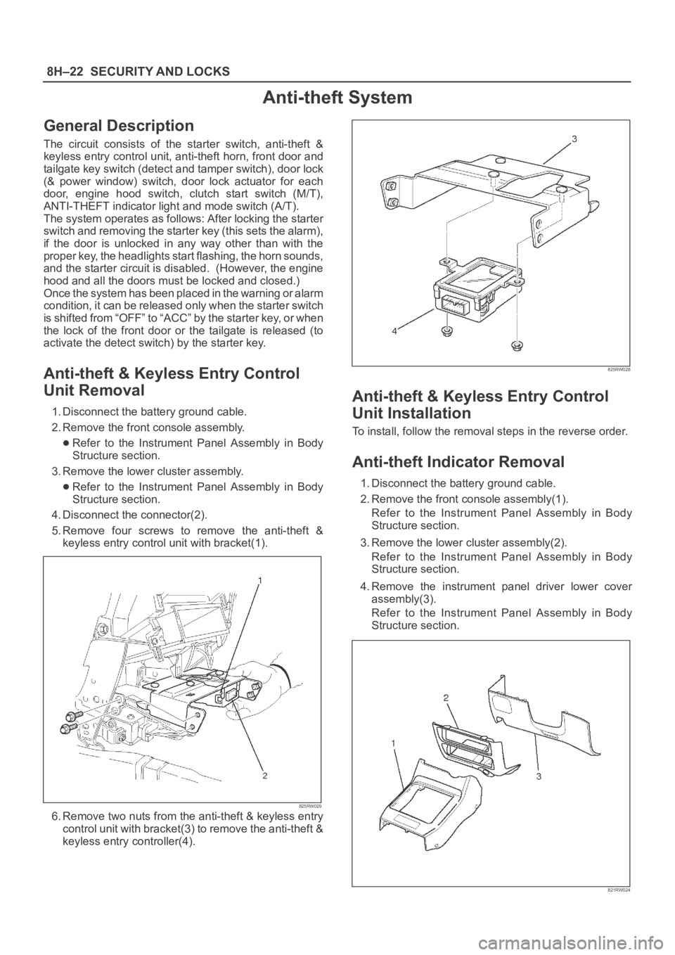
4. Disconnect the connector(2).
5. Remove four screws to remove the anti-theft &
keyless entry control unit with bracket(1).
825RW029
6. Remove two nuts from the anti-theft & keyless entry
control unit with bracket(3) to remove the anti-theft &
keyless entry controller(4).
825RW028
Anti-theft & Keyless Entry Control
Unit Installation
To install, follow the removal steps in the reverse order.
Anti-theft Indicator Removal
1. Disconnect the battery ground cable.
2. Remove the front console assembly(1).
Refer to the Instrument Panel Assembly in Body
Structure section.
3. Remove the lower cluster assembly(2).
Refer to the Instrument Panel Assembly in Body
Structure section.
4. Remove the instrument panel driver lower cover
assembly(3).
Refer to the Instrument Panel Assembly in Body
Structure section.
821RW024
Page 3393 of 6000
8J–14EXTERIOR/INTERIOR TRIM
Luggage Side and Quarter Upper Trim Cover (Long Wheel Base)
Luggage Side, Quarter Upper Trim Cover and Associated Parts
760RW017
Legend
(1) Assist Grip
(2) Rear Seat Belt Anchor Bolt Cover and Anchor
Bolt
(3) Quarter Upper Trim Cover
(4) Anchor Bolt
(5) Luggage Side Trim Cover
(6) Luggage Side Lower Cover
(7) Third Seat Assembly and seat Bracket(8) Third Seat Belt Anchor Bolt Cover and Anchor
Bolt
(9) Rear End Floor Trim Cover
(10) Luggage Side Cap
(11) Speaker Grille
(12) Rear Speaker
(13) Luggage Room Light
(14) Rear Roof Trim Cover
Removal
1. Disconnect the battery ground cable.
2. Remove the third seat assembly and seat bracket.
3. Remove the rear end floor trim cover.
4. Remove the luggage side cap.
Page 3422 of 6000
9A–2 SEAT BELT SYSTEM
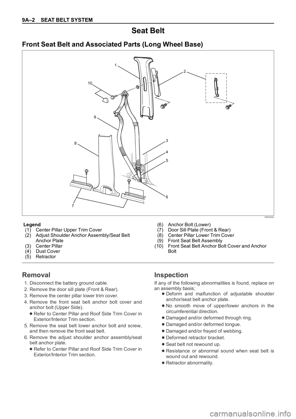
Legend
(1) Center Pillar Upper Trim Cover
(2) Adjust Shoulder Anchor Assembly/Seat Belt
Anchor Plate
(3) Center Pillar
(4) Dust Cover
(5) Retractor(6) Anchor Bolt (Lower)
(7) Door Sill Plate (Front & Rear)
(8) Center Pillar Lower Trim Cover
(9) Front Seat Belt Assembly
(10) Front Seat Belt Anchor Bolt Cover and Anchor
Bolt
Seat Belt
Front Seat Belt and Associated Parts (Long Wheel Base)
73
4
5
6 1
2
10
8
9
760RW022
Removal
1. Disconnect the battery ground cable.
2. Remove the door sill plate (Front & Rear).
3. Remove the center pillar lower trim cover.
4. Remove the front seat belt anchor bolt cover and
anchor bolt (Upper Side).
Refer to Center Pillar and Roof Side Trim Cover in
Exterior/Interior Trim section.
5. Remove the seat belt lower anchor bolt and screw,
and then remove the front seat belt.
6. Remove the adjust shoulder anchor assembly/seat
belt anchor plate.
Refer to Center Pillar and Roof Side Trim Cover in
Exterior/Interior Trim section.
Inspection
If any of the following abnormalities is found, replace on
an assembly basis;
Deform and malfunction of adjustable shoulder
anchor/seat belt anchor plate.
No smooth move of upper/lower anchors in the
circumferential direction.
Damaged and/or deformed through ring.
Damaged and/or deformed tongue.
Damaged and/or frayed of webbing.
Deformed retractor bracket.
Seat belt not rewound up.
Resistance or abnormal sound when seat belt is
wound out and rewound.
Retractor abnormality.
Page 3424 of 6000
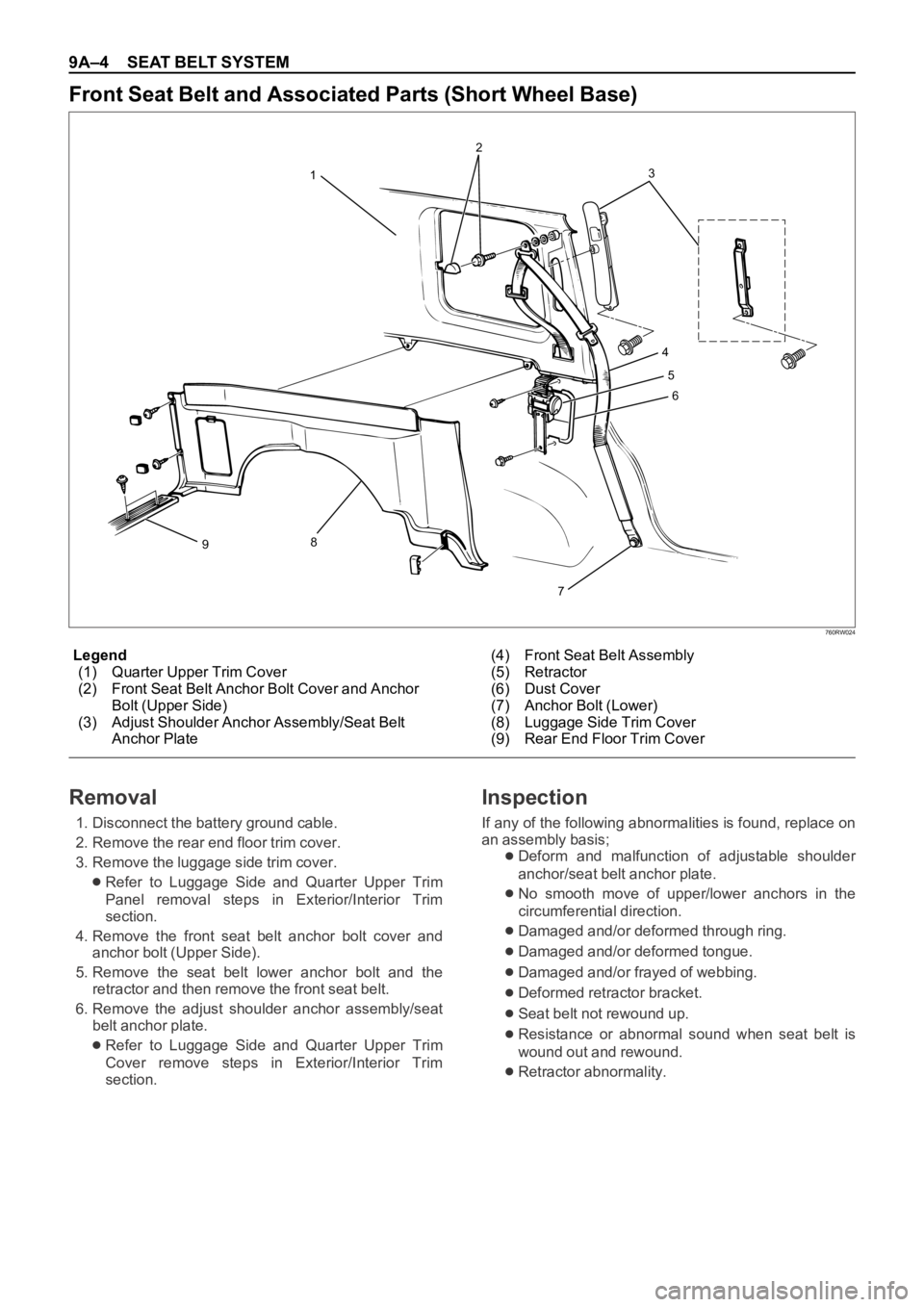
9A–4 SEAT BELT SYSTEM
760RW024
Legend
(1) Quarter Upper Trim Cover
(2) Front Seat Belt Anchor Bolt Cover and Anchor
Bolt (Upper Side)
(3) Adjust Shoulder Anchor Assembly/Seat Belt
Anchor Plate(4) Front Seat Belt Assembly
(5) Retractor
(6) Dust Cover
(7) Anchor Bolt (Lower)
(8) Luggage Side Trim Cover
(9) Rear End Floor Trim Cover
Front Seat Belt and Associated Parts (Short Wheel Base)
3
4
5
6
7
8
912
Removal
1. Disconnect the battery ground cable.
2. Remove the rear end floor trim cover.
3. Remove the luggage side trim cover.
Refer to Luggage Side and Quarter Upper Trim
Panel removal steps in Exterior/Interior Trim
section.
4. Remove the front seat belt anchor bolt cover and
anchor bolt (Upper Side).
5. Remove the seat belt lower anchor bolt and the
retractor and then remove the front seat belt.
6. Remove the adjust shoulder anchor assembly/seat
belt anchor plate.
Refer to Luggage Side and Quarter Upper Trim
Cover remove steps in Exterior/Interior Trim
section.
Inspection
If any of the following abnormalities is found, replace on
an assembly basis;
Deform and malfunction of adjustable shoulder
anchor/seat belt anchor plate.
No smooth move of upper/lower anchors in the
circumferential direction.
Damaged and/or deformed through ring.
Damaged and/or deformed tongue.
Damaged and/or frayed of webbing.
Deformed retractor bracket.
Seat belt not rewound up.
Resistance or abnormal sound when seat belt is
wound out and rewound.
Retractor abnormality.
Page 3426 of 6000
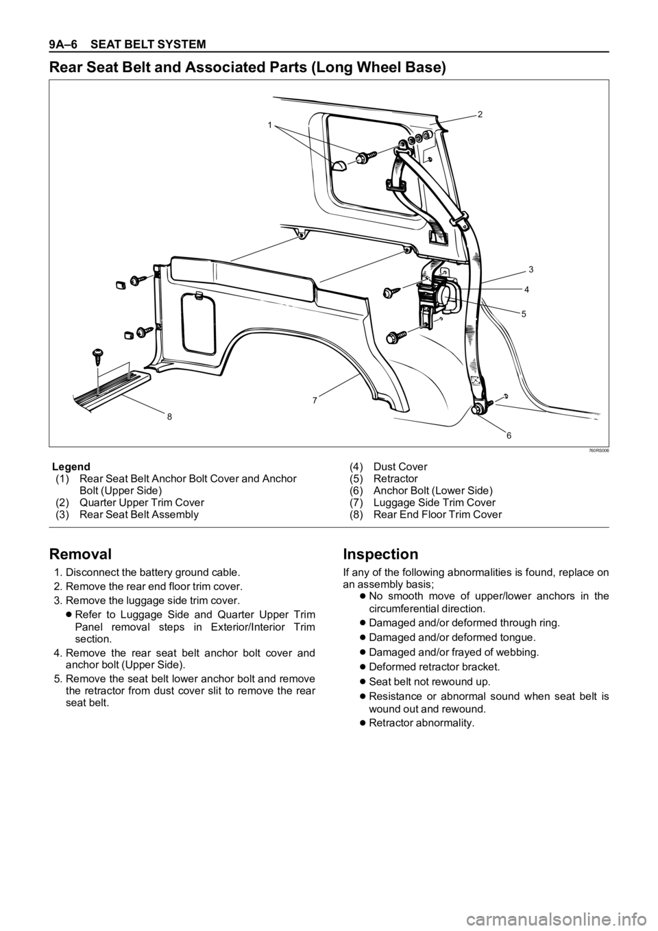
9A–6 SEAT BELT SYSTEM
760RS006
Legend
(1) Rear Seat Belt Anchor Bolt Cover and Anchor
Bolt (Upper Side)
(2) Quarter Upper Trim Cover
(3) Rear Seat Belt Assembly(4) Dust Cover
(5) Retractor
(6) Anchor Bolt (Lower Side)
(7) Luggage Side Trim Cover
(8) Rear End Floor Trim Cover
Rear Seat Belt and Associated Parts (Long Wheel Base)
12
3
4
5
6 7
8
Removal
1. Disconnect the battery ground cable.
2. Remove the rear end floor trim cover.
3. Remove the luggage side trim cover.
Refer to Luggage Side and Quarter Upper Trim
Panel removal steps in Exterior/Interior Trim
section.
4. Remove the rear seat belt anchor bolt cover and
anchor bolt (Upper Side).
5. Remove the seat belt lower anchor bolt and remove
the retractor from dust cover slit to remove the rear
seat belt.
Inspection
If any of the following abnormalities is found, replace on
an assembly basis;
No smooth move of upper/lower anchors in the
circumferential direction.
Damaged and/or deformed through ring.
Damaged and/or deformed tongue.
Damaged and/or frayed of webbing.
Deformed retractor bracket.
Seat belt not rewound up.
Resistance or abnormal sound when seat belt is
wound out and rewound.
Retractor abnormality.