1998 OPEL FRONTERA rack
[x] Cancel search: rackPage 3494 of 6000
9J1–7
RESTRAINT CONTROL SYSTEM
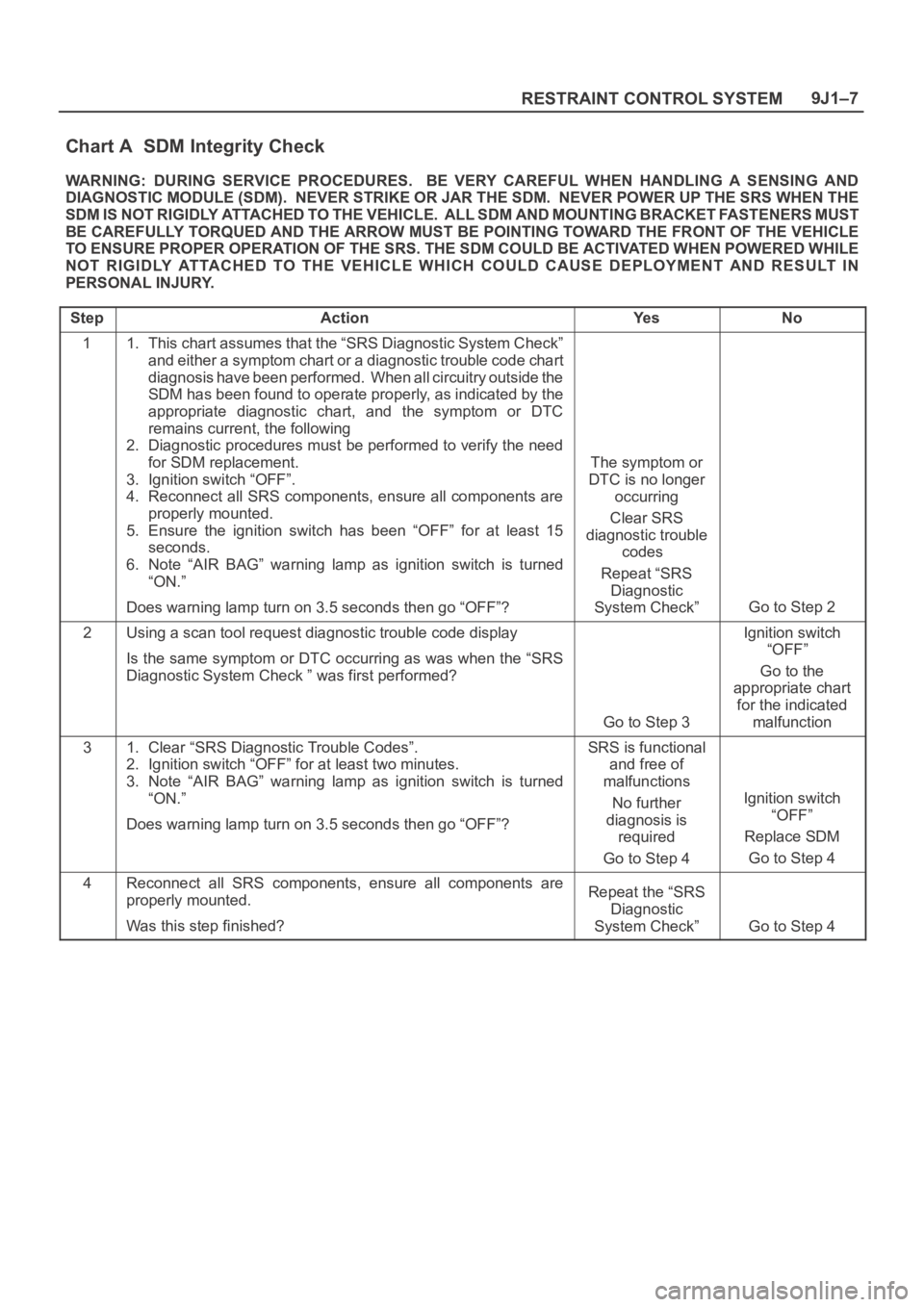
Chart A SDM Integrity Check
WARNING: DURING SERVICE PROCEDURES. BE VERY CAREFUL WHEN HANDLING A SENSING AND
DIAGNOSTIC MODULE (SDM). NEVER STRIKE OR JAR THE SDM. NEVER POWER UP THE SRS WHEN THE
S D M I S N O T R I G I D LY AT TA C H E D T O T H E V E H I C L E . A L L S D M A N D M O U N T ING BRACKET FASTENERS MUST
BE CAREFULLY TORQUED AND THE ARROW MUST BE POINTING TOWARD THE FRONT OF THE VEHICLE
TO ENSURE PROPER OPERATION OF THE SRS. THE SDM COULD BE ACTIVATED WHEN POWERED WHILE
NOT RIGIDLY ATTACHED TO THE VEHICLE WHICH COULD CAUSE DEPLOYMENT AND RESULT IN
PERSONAL INJURY.
Step
ActionYe sNo
11. This chart assumes that the “SRS Diagnostic System Check”
and either a symptom chart or a diagnostic trouble code chart
diagnosis have been performed. When all circuitry outside the
SDM has been found to operate properly, as indicated by the
appropriate diagnostic chart, and the symptom or DTC
remains current, the following
2. Diagnostic procedures must be performed to verify the need
for SDM replacement.
3. Ignition switch “OFF”.
4. Reconnect all SRS components, ensure all components are
properly mounted.
5. Ensure the ignition switch has been “OFF” for at least 15
seconds.
6. Note “AIR BAG” warning lamp as ignition switch is turned
“ON.”
Does warning lamp turn on 3.5 seconds then go “OFF”?
The symptom or
DTC is no longer
occurring
Clear SRS
diagnostic trouble
codes
Repeat “SRS
Diagnostic
System Check”
Go to Step 2
2Using a scan tool request diagnostic trouble code display
Is the same symptom or DTC occurring as was when the “SRS
Diagnostic System Check ” was first performed?
Go to Step 3
Ignition switch
“OFF”
Go to the
appropriate chart
for the indicated
malfunction
31. Clear “SRS Diagnostic Trouble Codes”.
2. Ignition switch “OFF” for at least two minutes.
3. Note “AIR BAG” warning lamp as ignition switch is turned
“ON.”
Does warning lamp turn on 3.5 seconds then go “OFF”?SRS is functional
and free of
malfunctions
No further
diagnosis is
required
Go to Step 4
Ignition switch
“OFF”
Replace SDM
Go to Step 4
4Reconnect all SRS components, ensure all components are
properly mounted.
Was this step finished?Repeat the “SRS
Diagnostic
System Check”
Go to Step 4
Page 3523 of 6000
RESTRAINT CONTROL SYSTEM 9J1–36
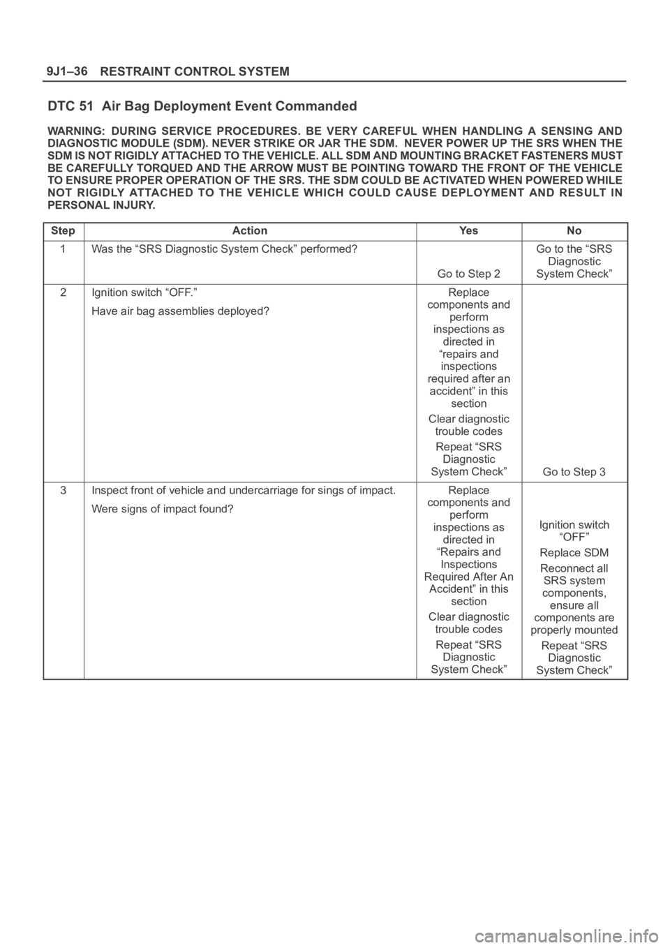
DTC 51 Air Bag Deployment Event Commanded
WARNING: DURING SERVICE PROCEDURES. BE VERY CAREFUL WHEN HANDLING A SENSING AND
DIAGNOSTIC MODULE (SDM). NEVER STRIKE OR JAR THE SDM. NEVER POWER UP THE SRS WHEN THE
SDM IS NOT RIGIDLY ATTACHED TO THE VEHICLE. ALL SDM AND MOUNTING BRACKET FASTENERS MUST
BE CAREFULLY TORQUED AND THE ARROW MUST BE POINTING TOWARD THE FRONT OF THE VEHICLE
TO ENSURE PROPER OPERATION OF THE SRS. THE SDM COULD BE ACTIVATED WHEN POWERED WHILE
NOT RIGIDLY ATTACHED TO THE VEHICLE WHICH COULD CAUSE DEPLOYMENT AND RESULT IN
PERSONAL INJURY.
Step
ActionYe sNo
1Was the “SRS Diagnostic System Check” performed?
Go to Step 2
Go to the “SRS
Diagnostic
System Check”
2Ignition switch “OFF.”
Have air bag assemblies deployed?Replace
components and
perform
inspections as
directed in
“repairs and
inspections
required after an
accident” in this
section
Clear diagnostic
trouble codes
Repeat “SRS
Diagnostic
System Check”
Go to Step 3
3Inspect front of vehicle and undercarriage for sings of impact.
Were signs of impact found?Replace
components and
perform
inspections as
directed in
“Repairs and
Inspections
Required After An
Accident” in this
section
Clear diagnostic
trouble codes
Repeat “SRS
Diagnostic
System Check”
Ignition switch
“OFF”
Replace SDM
Reconnect all
SRS system
components,
ensure all
components are
properly mounted
Repeat “SRS
Diagnostic
System Check”
Page 3525 of 6000
RESTRAINT CONTROL SYSTEM 9J1–38
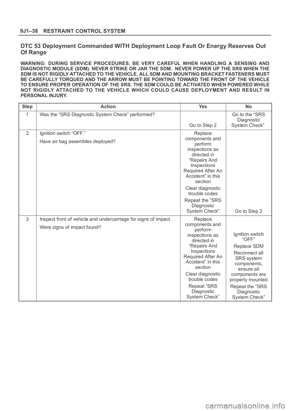
DTC 53 Deployment Commanded WITH Deployment Loop Fault Or Energy Reserves Out
Of Range
WARNING: DURING SERVICE PROCEDURES. BE VERY CAREFUL WHEN HANDLING A SENSING AND
DIAGNOSTIC MODULE (SDM). NEVER STRIKE OR JAR THE SDM. NEVER POWER UP THE SRS WHEN THE
SDM IS NOT RIGIDLY ATTACHED TO THE VEHICLE. ALL SDM AND MOUNTING BRACKET FASTENERS MUST
BE CAREFULLY TORQUED AND THE ARROW MUST BE POINTING TOWARD THE FRONT OF THE VEHICLE
TO ENSURE PROPER OPERATION OF THE SRS. THE SDM COULD BE ACTIVATED WHEN POWERED WHILE
NOT RIGIDLY ATTACHED TO THE VEHICLE WHICH COULD CAUSE DEPLOYMENT AND RESULT IN
PERSONAL INJURY.
Step
ActionYe sNo
1Was the “SRS Diagnostic System Check” performed?
Go to Step 2
Go to the “SRS
Diagnostic
System Check”
2Ignition switch “OFF.”
Have air bag assembles deployed?Replace
components and
perform
inspections as
directed in
“Repairs And
Inspections
Required After An
Accident” in this
section
Clear diagnostic
trouble codes
Repeat the “SRS
Diagnostic
System Check”
Go to Step 3
3Inspect front of vehicle and undercarriage for signs of impact.
Were signs of impact found?Replace
components and
perform
inspections as
directed in
“Repairs And
Inspections
Required After An
Accident” in this
section
Clear diagnostic
trouble codes
Repeat “SRS
Diagnostic
System Check”
Ignition switch
“OFF”
Replace SDM
Reconnect all
SRS system
components,
ensure all
components are
properly mounted
Repeat the “SRS
Diagnostic
System Check”
Page 3529 of 6000
RESTRAINT CONTROL SYSTEM 9J1–42
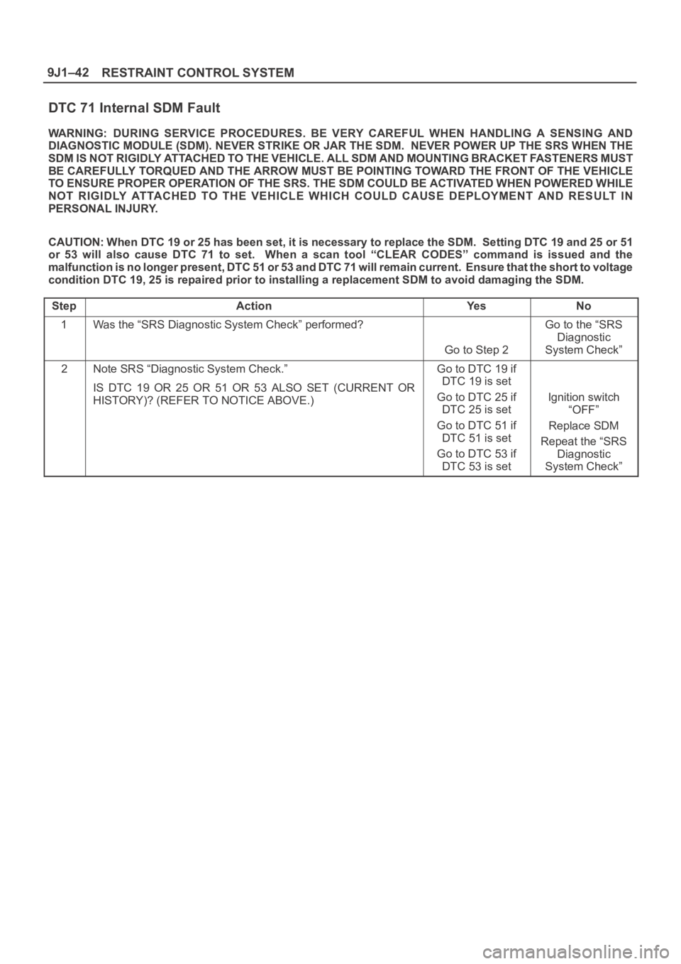
DTC 71 Internal SDM Fault
WARNING: DURING SERVICE PROCEDURES. BE VERY CAREFUL WHEN HANDLING A SENSING AND
DIAGNOSTIC MODULE (SDM). NEVER STRIKE OR JAR THE SDM. NEVER POWER UP THE SRS WHEN THE
SDM IS NOT RIGIDLY ATTACHED TO THE VEHICLE. ALL SDM AND MOUNTING BRACKET FASTENERS MUST
BE CAREFULLY TORQUED AND THE ARROW MUST BE POINTING TOWARD THE FRONT OF THE VEHICLE
TO ENSURE PROPER OPERATION OF THE SRS. THE SDM COULD BE ACTIVATED WHEN POWERED WHILE
NOT RIGIDLY ATTACHED TO THE VEHICLE WHICH COULD CAUSE DEPLOYMENT AND RESULT IN
PERSONAL INJURY.
CAUTION: When DTC 19 or 25 has been set, it is necessary to replace the SDM. Setting DTC 19 and 25 or 51
or 53 will also cause DTC 71 to set. When a scan tool “CLEAR CODES” command is issued and the
malfunction is no longer present, DTC 51 or 53 and DTC 71 will remain current. Ensure that the short to voltage
condition DTC 19, 25 is repaired prior to installing a replacement SDM to avoid damaging the SDM.
Step
ActionYe sNo
1Was the “SRS Diagnostic System Check” performed?
Go to Step 2
Go to the “SRS
Diagnostic
System Check”
2Note SRS “Diagnostic System Check.”
IS DTC 19 OR 25 OR 51 OR 53 ALSO SET (CURRENT OR
HISTORY)? (REFER TO NOTICE ABOVE.)Go to DTC 19 if
DTC 19 is set
Go to DTC 25 if
DTC 25 is set
Go to DTC 51 if
DTC 51 is set
Go to DTC 53 if
DTC 53 is set
Ignition switch
“OFF”
Replace SDM
Repeat the “SRS
Diagnostic
System Check”
Page 3551 of 6000
RESTRAINT CONTROL SYSTEM 9J1–64
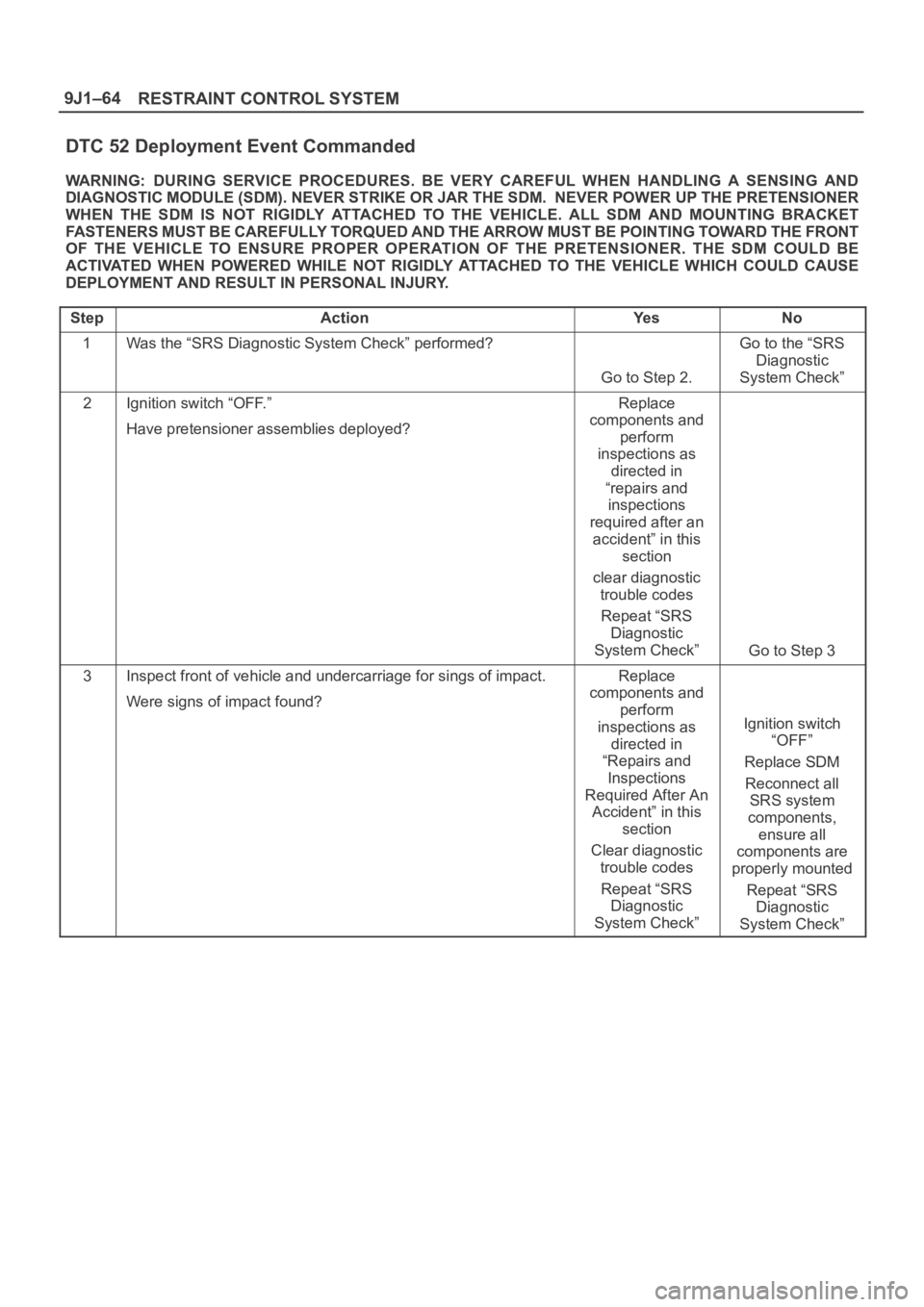
DTC 52 Deployment Event Commanded
WARNING: DURING SERVICE PROCEDURES. BE VERY CAREFUL WHEN HANDLING A SENSING AND
DIAGNOSTIC MODULE (SDM). NEVER STRIKE OR JAR THE SDM. NEVER POWER UP THE PRETENSIONER
WHEN THE SDM IS NOT RIGIDLY ATTACHED TO THE VEHICLE. ALL SDM AND MOUNTING BRACKET
FASTENERS MUST BE CAREFULLY TORQUED AND THE ARROW MUST BE POINTING TOWARD THE FRONT
OF THE VEHICLE TO ENSURE PROPER OPERATION OF THE PRETENSIONER. THE SDM COULD BE
ACTIVATED WHEN POWERED WHILE NOT RIGIDLY ATTACHED TO THE VEHICLE WHICH COULD CAUSE
DEPLOYMENT AND RESULT IN PERSONAL INJURY.
Step
ActionYe sNo
1Was the “SRS Diagnostic System Check” performed?
Go to Step 2.
Go to the “SRS
Diagnostic
System Check”
2Ignition switch “OFF.”
Have pretensioner assemblies deployed?Replace
components and
perform
inspections as
directed in
“repairs and
inspections
required after an
accident” in this
section
clear diagnostic
trouble codes
Repeat “SRS
Diagnostic
System Check”
Go to Step 3
3Inspect front of vehicle and undercarriage for sings of impact.
Were signs of impact found?Replace
components and
perform
inspections as
directed in
“Repairs and
Inspections
Required After An
Accident” in this
section
Clear diagnostic
trouble codes
Repeat “SRS
Diagnostic
System Check”
Ignition switch
“OFF”
Replace SDM
Reconnect all
SRS system
components,
ensure all
components are
properly mounted
Repeat “SRS
Diagnostic
System Check”
Page 3767 of 6000
Inspection and Repair
Drive Plate
If the frictional surface shows signs of damage due to
excessive heat, the drive plate and pulley should be
replaced.
Pulley Assembly
Check the appearance of the pulley assembly. If the
frictional surface of the pulley shows signs of excessive
grooving due to slippage, both the pulley and drive
plate should be replaced. The frictional surfaces of the
pulley assembly should be cleaned with a suitable
solvent before reinstallation.
Coil
Check coil for loose connector or cracked insulation.
Installation
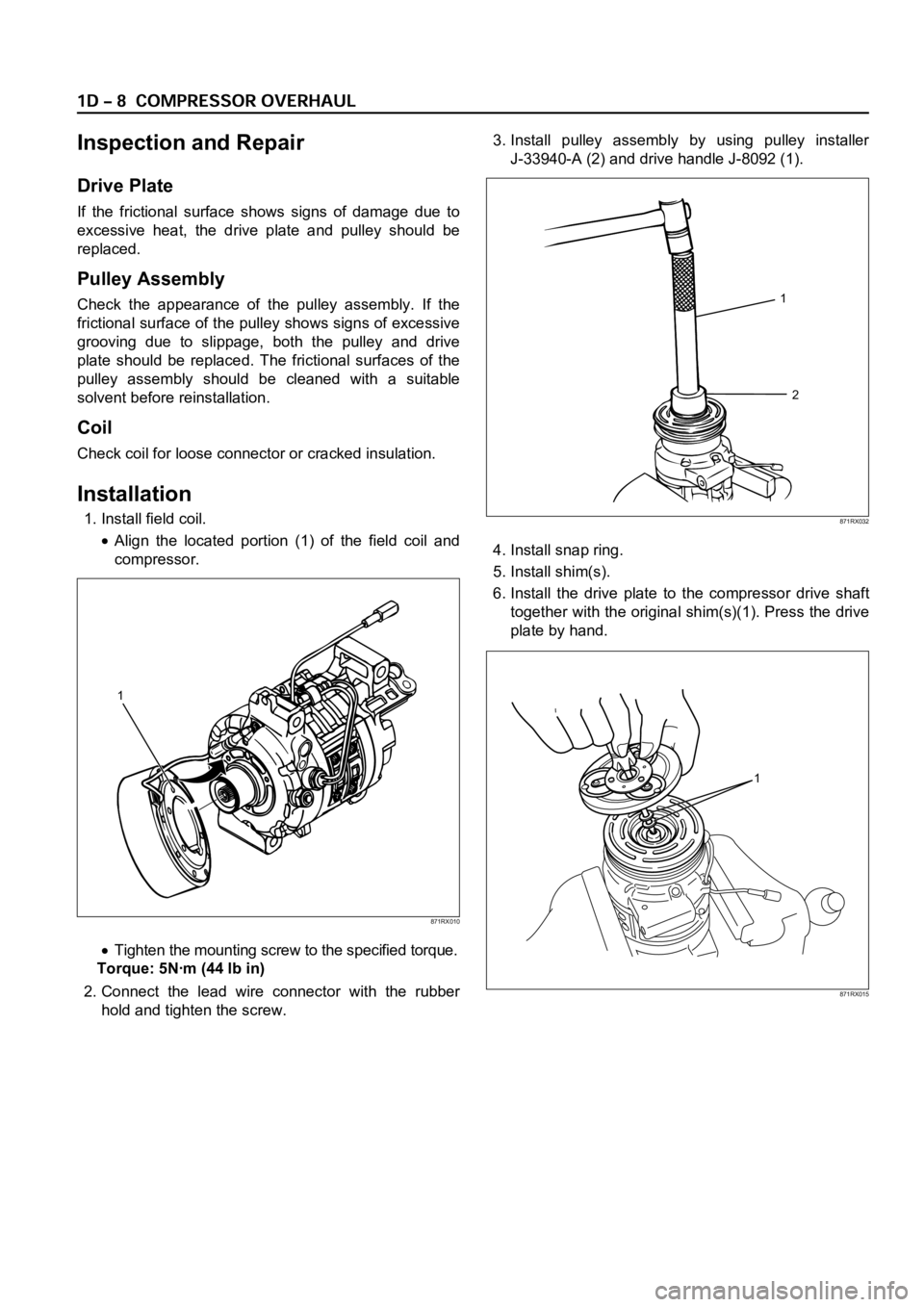
1. Install field coil.
Align the located portion (1) of the field coil and
compressor.
Tighten the mounting screw to the specified torque.
Torque: 5Nꞏm (44 lb in)
2. Connect the lead wire connector with the rubber
hold and tighten the screw.3. Install pulley assembly by using pulley installer
J-33940-A (2) and drive handle J-8092 (1).
4. Install snap ring.
5. Install shim(s).
6. Install the drive plate to the compressor drive shaft
together with the original shim(s)(1). Press the drive
plate by hand.
1
2
871RX032
1
871RX010
1
871RX015
Page 3772 of 6000
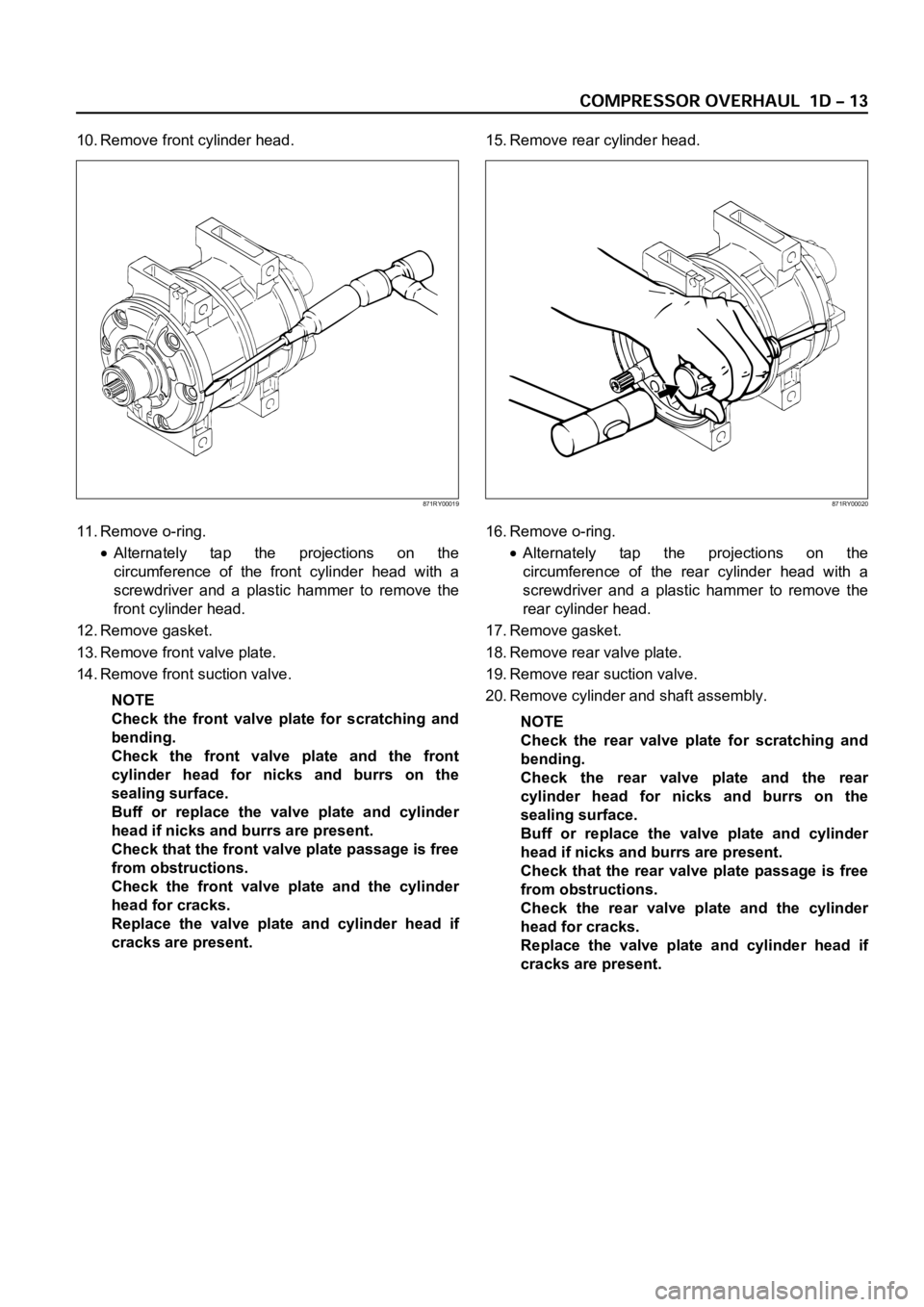
10. Remove front cylinder head.
11. Remove o-ring.
Alternately tap the projections on the
circumference of the front cylinder head with a
screwdriver and a plastic hammer to remove the
front cylinder head.
12. Remove gasket.
13. Remove front valve plate.
14. Remove front suction valve.
NOTE
Check the front valve plate for scratching and
bending.
Check the front valve plate and the front
cylinder head for nicks and burrs on the
sealing surface.
Buff or replace the valve plate and cylinder
head if nicks and burrs are present.
Check that the front valve plate passage is free
from obstructions.
Check the front valve plate and the cylinder
head for cracks.
Replace the valve plate and cylinder head if
cracks are present.15. Remove rear cylinder head.
16. Remove o-ring.Alternately tap the projections on the
circumference of the rear cylinder head with a
screwdriver and a plastic hammer to remove the
rear cylinder head.
17. Remove gasket.
18. Remove rear valve plate.
19. Remove rear suction valve.
20. Remove cylinder and shaft assembly.
NOTE
Check the rear valve plate for scratching and
bending.
Check the rear valve plate and the rear
cylinder head for nicks and burrs on the
sealing surface.
Buff or replace the valve plate and cylinder
head if nicks and burrs are present.
Check that the rear valve plate passage is free
from obstructions.
Check the rear valve plate and the cylinder
head for cracks.
Replace the valve plate and cylinder head if
cracks are present.
871RY00019871RY00020
Page 3777 of 6000
HD6 TYPE COMPRESSOR
Metric Thread Size Information
Compressor to mounting bracket bolts (Front)
M10
1.5 – 6H
Compressor to mounting bracket bolts (Rear)
M8
1.25 – 6H
Suction-discharge port screw
M10
1.5 – 6HCompressor shaft
M9
1.25 – 6H
Internal hub-clutch drive assembly
M22
1.5 – 6H
COMPRESSOR CLUTCH PLATE AND HUB
ASSEMBLY
Removal
1. Clamp the holding fixture J-33026 in a vise and
attach compressor to holding fixture with thumb
screws J-33026-1.
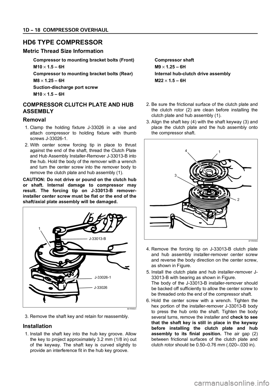
2. With center screw forcing tip in place to thrust
against the end of the shaft, thread the Clutch Plate
and Hub Assembly Installer-Remover J-33013-B into
the hub. Hold the body of the remover with a wrench
and turn the center screw into the remover body to
remove the clutch plate and hub assembly (1).
CAUTION: Do not drive or pound on the clutch hub
or shaft. Internal damage to compressor may
result. The forcing tip on J-33013-B remover-
installer center screw must be flat or the end of the
shaft/axial plate assembly will be damaged.
3. Remove the shaft key and retain for reassembly.
Installation
1. Install the shaft key into the hub key groove. Allow
the key to project approximately 3.2 mm (1/8 in) out
of the keyway. The shaft key is curved slightly to
provide an interference fit in the hub key groove.2. Be sure the frictional surface of the clutch plate and
the clutch rotor (2) are clean before installing the
clutch plate and hub assembly (1).
3. Align the shaft key (4) with the shaft keyway (3) and
place the clutch plate and the hub assembly onto
the compressor shaft.
4. Remove the forcing tip on J-33013-B clutch plate
and hub assembly installer-remover center screw
and reverse the body direction on the center screw,
as shown in Figure.
5. Install the clutch plate and hub installer-remover J-
33013-B with bearing as shown in Figure.
The body of the J-33013-B installer-remover should
be backed off sufficiently to allow the center screw to
be threaded onto the end of the compressor shaft.
6. Hold the center screw with a wrench. Tighten the
hex portion of the installer-remover J-33013-B body
to press the hub onto the shaft. Tighten the body
several turns, remove the installer and check to see
that the shaft key is still in place in the keyway
before installing the clutch plate and hub
assembly to its finial position.The air gap (2)
between frictional surfaces of the clutch plate and
clutch rotor should be 0.50–0.76 mm (.020–.030 in).
1
J-33013-B
J-33026-1
J-33026
901RW001
4
31
2
871RW003