1998 OPEL FRONTERA rack
[x] Cancel search: rackPage 3429 of 6000
SEAT BELT SYSTEM 9A–9
3. Remove the rear end floor trim cover.
4. Remove the luggage side trim cover.
Refer to Luggage Side and Quarter Upper Trim
Panel removal steps in Exterior/Interior Trim
section.
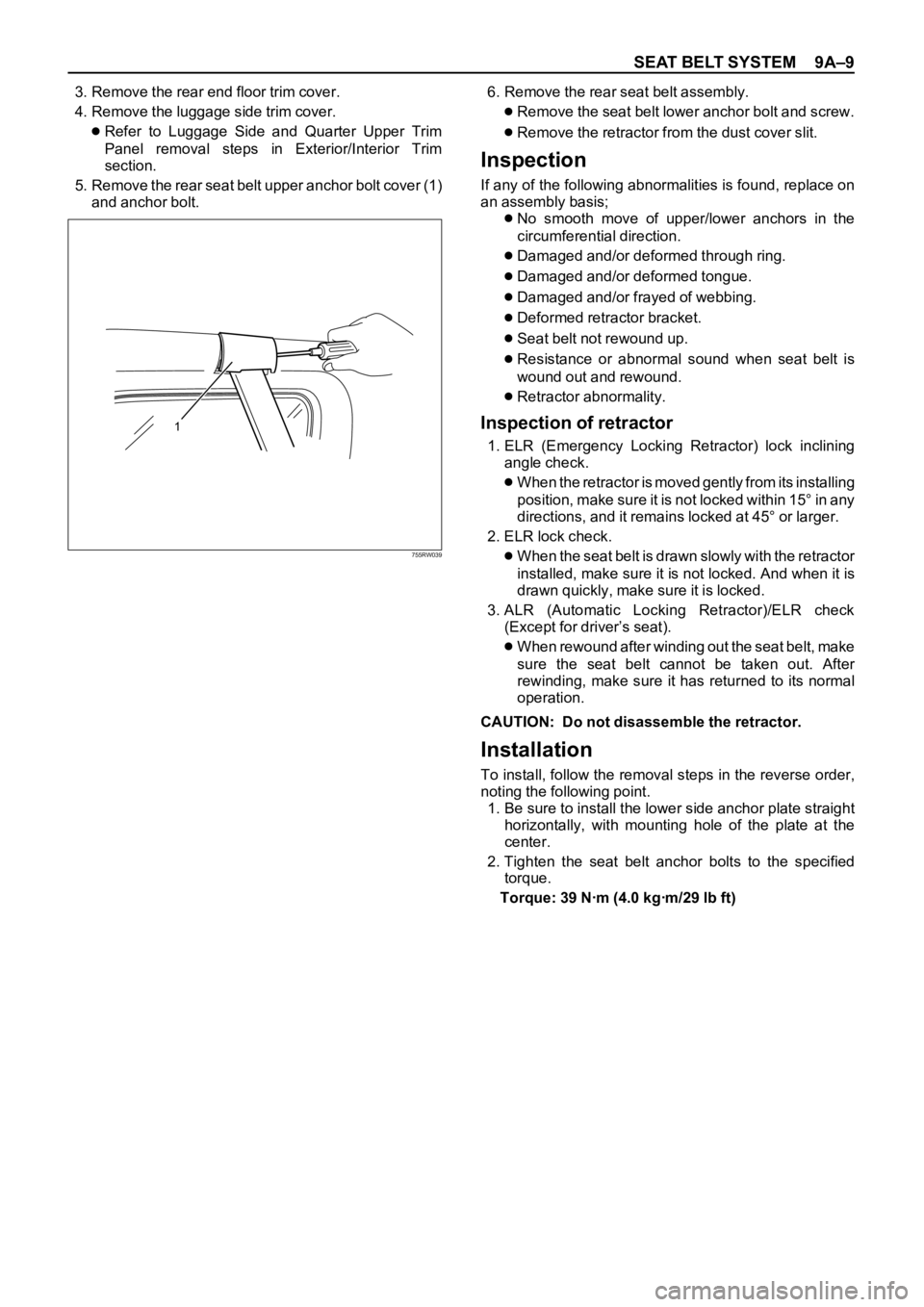
5. Remove the rear seat belt upper anchor bolt cover (1)
and anchor bolt.6. Remove the rear seat belt assembly.
Remove the seat belt lower anchor bolt and screw.
Remove the retractor from the dust cover slit.
Inspection
If any of the following abnormalities is found, replace on
an assembly basis;
No smooth move of upper/lower anchors in the
circumferential direction.
Damaged and/or deformed through ring.
Damaged and/or deformed tongue.
Damaged and/or frayed of webbing.
Deformed retractor bracket.
Seat belt not rewound up.
Resistance or abnormal sound when seat belt is
wound out and rewound.
Retractor abnormality.
Inspection of retractor
1. ELR (Emergency Locking Retractor) lock inclining
angle check.
When the retractor is moved gently from its installing
position, make sure it is not locked within 15° in any
directions, and it remains locked at 45° or larger.
2. ELR lock check.
When the seat belt is drawn slowly with the retractor
installed, make sure it is not locked. And when it is
drawn quickly, make sure it is locked.
3. ALR (Automatic Locking Retractor)/ELR check
(Except for driver’s seat).
When rewound after winding out the seat belt, make
sure the seat belt cannot be taken out. After
rewinding, make sure it has returned to its normal
operation.
CAUTION: Do not disassemble the retractor.
Installation
To install, follow the removal steps in the reverse order,
noting the following point.
1. Be sure to install the lower side anchor plate straight
horizontally, with mounting hole of the plate at the
center.
2. Tighten the seat belt anchor bolts to the specified
torque.
Torque: 39 Nꞏm (4.0 kgꞏm/29 lb ft)
1
755RW039
Page 3431 of 6000

SEAT BELT SYSTEM 9A–11
Inspection
If any of the following abnormalities is found, replace on
an assembly basis;
No smooth move of upper/lower anchors in the
circumferential direction.
Damaged and/or deformed through ring.
Damaged and/or deformed tongue.
Damaged and/or frayed of webbing.
Deformed retractor bracket.
Seat belt not rewound up.
Resistance or abnormal sound when seat belt is
wound out and rewound.
Retractor abnormality.
Inspection of retractor
1. ELR (Emergency Locking Retractor) lock inclining
angle check.
When the retractor is moved gently from its installing
position, make sure it is not locked within 15° in any
directions, and it remains locked at 45° or larger.
2. ELR lock check.
When the seat belt is drawn slowly with the retractor
installed, make sure it is not locked. And when it is
drawn quickly, make sure it is locked.
CAUTION: Do not disassemble the retractor.
Installation
To install, follow the removal steps in the reverse order,
noting the following point.
1. Be sure to install the lower side anchor plate (1)
straight against the longitudinal direction of the
vehicle with mounting hole of the plate at the center.
2. Tighten the seat belt anchor bolts to the specified
torque.
Torque: 39 Nꞏm (4.0 kgꞏm/29 lb ft)
Page 3441 of 6000
SUPPLEMENTAL RESTRAINT SYSTEM 9J–4
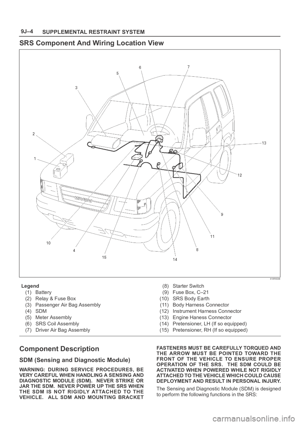
SRS Component And Wiring Location View
810RW298
Legend
(1) Battery
(2) Relay & Fuse Box
(3) Passenger Air Bag Assembly
(4) SDM
(5) Meter Assembly
(6) SRS Coil Assembly
(7) Driver Air Bag Assembly(8) Starter Switch
(9) Fuse Box, C–21
(10) SRS Body Earth
(11) Body Harness Connector
(12) Instrument Harness Connector
(13) Engine Haness Connector
(14) Pretensioner, LH (If so equipped)
(15) Pretensioner, RH (If so equipped)
Component Description
SDM (Sensing and Diagnostic Module)
WARNING: DURING SERVICE PROCEDURES, BE
VERY CAREFUL WHEN HANDLING A SENSING AND
DIAGNOSTIC MODULE (SDM). NEVER STRIKE OR
JAR THE SDM. NEVER POWER UP THE SRS WHEN
THE SDM IS NOT RIGIDLY ATTACHED TO THE
VEHICLE. ALL SDM AND MOUNTING BRACKETFASTENERS MUST BE CAREFULLY TORQUED AND
THE ARROW MUST BE POINTED TOWARD THE
FRONT OF THE VEHICLE TO ENSURE PROPER
OPERATION OF THE SRS. THE SDM COULD BE
ACTIVATED WHEN POWERED WHILE NOT RIGIDLY
ATTACHED TO THE VEHICLE WHICH COULD CAUSE
DEPLOYMENT AND RESULT IN PERSONAL INJURY.
The Sensing and Diagnostic Module (SDM) is designed
to perform the following functions in the SRS:
Page 3446 of 6000
SUPPLEMENTAL RESTRAINT SYSTEM9J–9
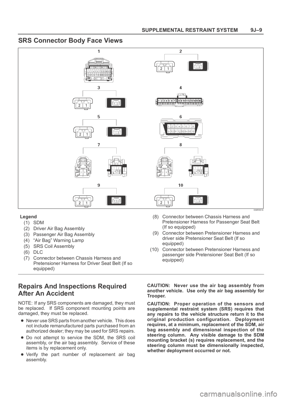
SRS Connector Body Face Views
D09RW016
Legend
(1) SDM
(2) Driver Air Bag Assembly
(3) Passenger Air Bag Assembly
(4) “Air Bag” Warning Lamp
(5) SRS Coil Assembly
(6) DLC
(7) Connector between Chassis Harness and
Pretensioner Harness for Driver Seat Belt (If so
equipped)(8) Connector between Chassis Harness and
Pretensioner Harness for Passenger Seat Belt
(If so equipped)
(9) Connector between Pretensioner Harness and
driver side Pretensioner Seat Belt (If so
equipped)
(10) Connector between Pretensioner Harness and
passenger side Pretensioner Seat Belt (If so
equipped)
Repairs And Inspections Required
After An Accident
NOTE: If any SRS components are damaged, they must
be replaced. If SRS component mounting points are
damaged, they must be replaced.
Never use SRS parts from another vehicle. This does
not include remanufactured parts purchased from an
a u t h o r i z e d d e a l e r ; t h e y m a y b e u s e d f o r S R S r e p a i r s .
Do not attempt to service the SDM, the SRS coil
assembly, or the air bag assembly. Service of these
items is by replacement only.
Verify the part number of replacement air bag
assembly.CAUTION: Never use the air bag assembly from
another vehicle. Use only the air bag assembly for
Trooper.
CAUTION: Proper operation of the sensors and
supplemental restraint system (SRS) requires that
any repairs to the vehicle structure return it to the
original production configuration. Deployment
requires, at a minimum, replacement of the SDM, air
bag assembly and dimensional inspection of the
steering column. Any visible damage to the SDM
mounting bracket (s) requires replacement, and the
steering column must be dimensionally inspected,
whether deployment occurred or not.
Page 3447 of 6000
SUPPLEMENTAL RESTRAINT SYSTEM 9J–10
Accident With Deployment – Component
Replacement And Inspections
Certain SRS components must be replaced or inspected
for damage after a frontal crash involving air bag
deployment. Those components are:
Air bag assembly
SDM
CAUTION: Refer to “SDM Replacement Guidelines”
below for important information on SDM
replacement in both deployment and non
deployment crashes.
SRS coil assembly — Inspect wiring and connector
for any signs of scorching, melting, or damage due to
excessive heat. Replace if damaged. Refer to
section “SRS Coil Assembly” in this manual.
Accident With or Without Deployment –
Component Inspection
Certain SRS system components and rotation parts must
be inspected after any crash, whether the air bag
deployed or not. Those components are:
Steering column — Refer to Inspection Required
“After an Accident” in this manual.
Knee bolsters and mounting points — Inspect for any
distortion, bending, cracking, or other damage.
I/P steering column reinforcement plate — Inspect for
any distortion, bending, cracking, or other damage.
I/P braces — Inspect for any distortion, bending,
cracking, or other damage.
Seat belts and mounting points — Refer to “Seat
Belts” in Section “Seat Belt” of this workshop manual.
SDM Replacement Guidelines
SDM replacement policy requires replacement of SDM,
after crash involving air bag deployment when “SRS
Warning Lamp” turn “ON”, “SRS Diagnosis” should be
done according to Section “Restraint Control System.”
If accident without deployment air bag, it is not necessary
replacement of SDM when do not indicate to replace the
SDM by scan tool after SRS system check.
Wiring Damage
If any SRS wire harness is damaged, it should be
replaced. Don’t repair SRS harness. It is replace only.
SRS Connector (Plastic Body And
Terminal Metal Pin) Damage
If any connector or terminal in the SRS wire harness
(except pigtails) is damaged, it should be replaced.
SRS Wire Pigtail Damage
If the wiring pigtail (a wire or wires attached directly to the
device, not by a connector) is damaged, the entire
component (with pigtail) must be replaced. Examples of
“pigtail” components are the driver air bag assembly, the
passenger air bag assembly, and the SRS coil assembly.
On–Vehicle Service
Service Precaution
WARNING: WHEN PERFORMING SERVICE ON OR
AROUND SRS COMPONENTS OR SRS WIRING,
FOLLOW THE PROCEDURES LISTED BELOW TO
TEMPORARILY DISABLE THE SRS. FAILURE TO
FOLLOW PROCEDURES COULD RESULT IN
POSSIBLE AIR BAG DEPLOYMENT, PERSONAL
INJURY OR OTHERWISE UNNEEDED SRS REPAIRS.
The SDM in Driver–Passenger SRS can maintain
sufficient voltage to cause a deployment for up to 15
seconds after the ignition switch is turned “OFF,” the
battery is disconnected, or the fuse powering the SDM is
removed.
Many of the service procedures require removal of the
“C–21” fuse, and disconnection of the air bag assembly
from the deployment loop to avoid an accidental
deployment. If the air bag assembly is disconnected from
the deployment loop as noted in the “Disabling the SRS”
procedure that follows, service can begin immediately
without waiting for the 15 second time period to expire.
Disabling The SRS
Removal
Turn the ignition switch to “LOCK” and remove key.
1. Remove SRS fuse C–21, from left dash side lower
fuse block or disconnect battery.
2. Disconnect yellow 2–pin connector at the base of
steering column.
3. Remove glove box assembly, refer to “Passenger Air
Bag Assembly Replacement” in this manual.
4. Disconnect yellow 2–pin connector behind the glove
box assembly.
CAUTION: With the “C–21” fuse removed and
ignition switch “ON”, the “AIR BAG” warning lamp
will be “ON”. This is normal operation and does not
indicate an SRS malfunction.
Enabling The SRS
Installation
CAUTION: Never use the air bag assembly from
another vehicle. Use only the air bag assembly for
Trooper.
Turn ignition switch to “LOCK” and remove key.
1. Connect yellow 2–pin connector passenger air bag
assembly.
2. Install glove box assembly. Refer to “Passenger air
bag assembly replacement” in this manual.
3. Connect yellow 2–pin connector at the base of
steering column.
4. Install “AIR BAG” fuse C–21 to left dash side lower
fuse block or connect battery.
Turn ignition switch to “ON” and verify that the “AIR BAG”
warning lamp turn on 3.5 seconds and then turns “OFF.” If
it does not operate as described, perform the “SRS
Diagnostic System Check” in this manual.
Page 3470 of 6000
SUPPLEMENTAL RESTRAINT SYSTEM9J–33
Sensing And Diagnostic Module (SDM)
Service Precautions
WARNING: DURING SERVICE PROCEDURES, BE
VERY CAREFUL WHEN HANDLING SDM. NEVER
STRIKE OR JAR SDM. UNDER SOME
CIRCUMSTANCES, IT COULD CAUSE
DEPLOYMENT AND RESULT IN PERSONAL INJURY
OR IMPROPER OPERATION OF THE
SUPPLEMENTAL RESTRAINT SYSTEM (SRS) . SDM
MOUNTING BRACKET BOLTS MUST BE
CAREFULLY TORQUED TO ASSURE PROPER
OPERATION. NEVER POWER UP THE SRS WHEN
SDM IS NOT RIGIDLY ATTACHED TO THE VEHICLE.
THE SDM COULD BE ACTIVATED WHEN POWERED
WHILE NOT RIGIDLY ATTACHED TO THE VEHICLE
WHICH COULD CAUSE DEPLOYMENT AND RESULT
IN PERSONAL INJURY.
WARNING: PROPER OPERATION OF THE SENSING
AND DIAGNOSTIC MODULE (SDM) REQUIRES THE
SDM TO BE RIGIDLY ATTACHED TO THE VEHICLE
STRUCTURE AND THAT THE ARROW ON THE
SENSOR BE POINTING TOWARD THE FRONT OF
THE VEHICLE.
SDM is specifically calibrated and is keyed to the SDM
location SRS wiring harness. Caution should be used to
ensure proper location of the SDM. The keying of the
SDM to its location and wiring harness connectors should
never be modified in the field.
Removal
1. Disable the SRS (Refer to “Disabling the SRS” in this
section).
2. Remove the transmission knob (for M/T) and transfer
lever knob.
3. Remove the front console assembly and disconnect
wiring harness connector.
4. Pull CPA (Connector Position Assurance) out and
push connector lock down to disconnect the SDM
harness connector.
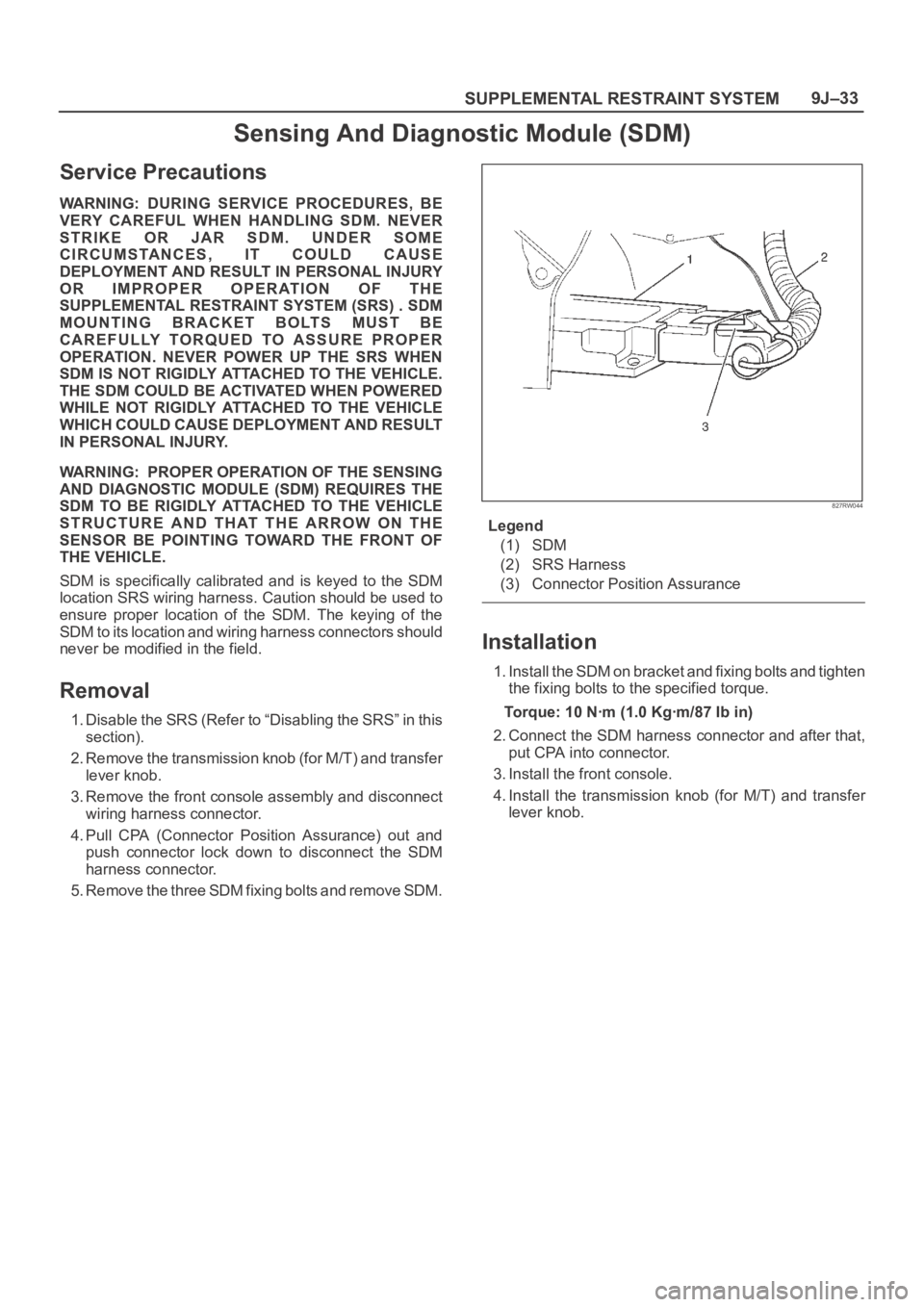
5. Remove the three SDM fixing bolts and remove SDM.
827RW044
Legend
(1) SDM
(2) SRS Harness
(3) Connector Position Assurance
Installation
1. Install the SDM on bracket and fixing bolts and tighten
the fixing bolts to the specified torque.
Torque: 10 Nꞏm (1.0 Kgꞏm/87 Ib in)
2. Connect the SDM harness connector and after that,
put CPA into connector.
3. Install the front console.
4. Install the transmission knob (for M/T) and transfer
lever knob.
Page 3483 of 6000
SUPPLEMENTAL RESTRAINT SYSTEM 9J–46
NOTE: SRS coil is a part of combination switch
assembly, which cannot be replaced separately.
Therefore, be sure not to remove the SRS coil from the
combination switch assembly.
15. Remove the snap ring.
16. Remove the cushion rubber.
17. Disconnect shift lock cable (A/T only).
18. Disconnect the starter switch harness connector
located base of steering column.
19. Remove steering lock cylinder assembly.
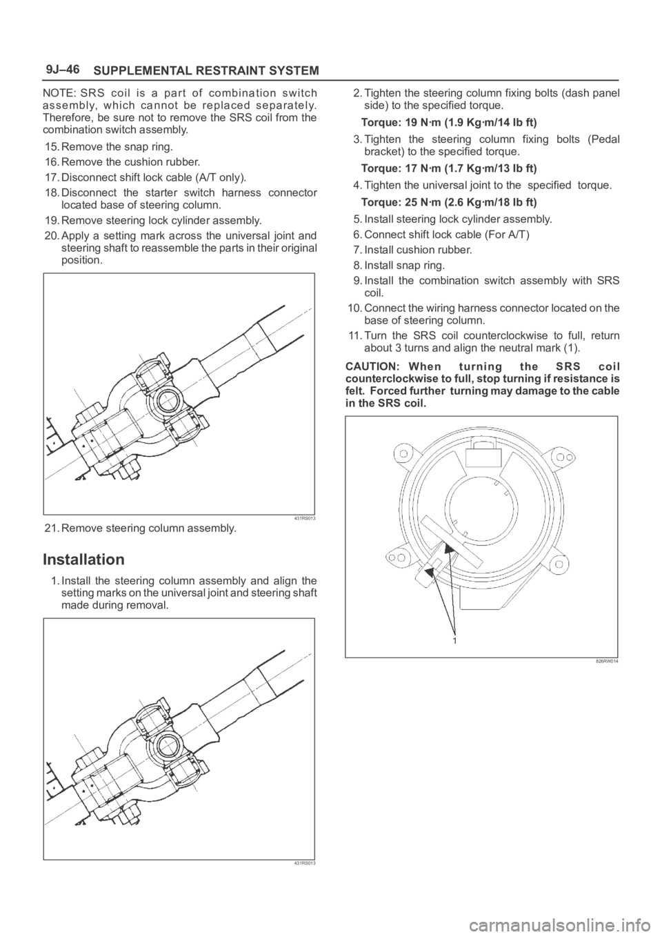
20. Apply a setting mark across the universal joint and
steering shaft to reassemble the parts in their original
position.
431RS013
21. Remove steering column assembly.
Installation
1. Install the steering column assembly and align the
setting marks on the universal joint and steering shaft
made during removal.
431RS013
2. Tighten the steering column fixing bolts (dash panel
side) to the specified torque.
Torque: 19 Nꞏm (1.9 Kgꞏm/14 Ib ft)
3. Tighten the steering column fixing bolts (Pedal
bracket) to the specified torque.
Torque: 17 Nꞏm (1.7 Kgꞏm/13 Ib ft)
4. Tighten the universal joint to the specified torque.
Torque: 25 Nꞏm (2.6 Kgꞏm/18 Ib ft)
5. Install steering lock cylinder assembly.
6. Connect shift lock cable (For A/T)
7. Install cushion rubber.
8. Install snap ring.
9. Install the combination switch assembly with SRS
coil.
10. Connect the wiring harness connector located on the
base of steering column.
11. Turn the SRS coil counterclockwise to full, return
about 3 turns and align the neutral mark (1).
CAUTION: W h e n t u r n i n g t h e S R S c o i l
counterclockwise to full, stop turning if resistance is
felt. Forced further turning may damage to the cable
in the SRS coil.
826RW014
Page 3487 of 6000
SUPPLEMENTAL RESTRAINT SYSTEM 9J–50
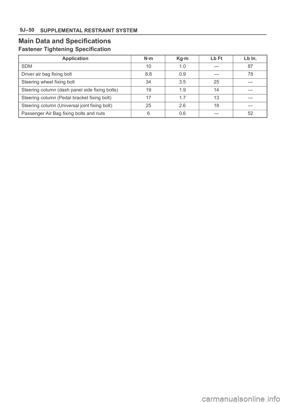
Main Data and Specifications
Fastener Tightening Specification
ApplicationNꞏmKgꞏmLb FtLb In.
SDM101.0—87
Driver air bag fixing bolt8.80.9—78
Steering wheel fixing bolt343.525—
Steering column (dash panel side fixing bolts)191.914—
Steering column (Pedal bracket fixing bolt)171.713—
Steering column (Universal joint fixing bolt)252.618—
Passenger Air Bag fixing bolts and nuts60.6—52