Page 4269 of 6000

4D1–8
TRANSFER CASE (STANDARD TYPE)
Transfer Rear Oil Seal
Removal
1. Disconnect the rear propeller shaft from the transfer
case side.
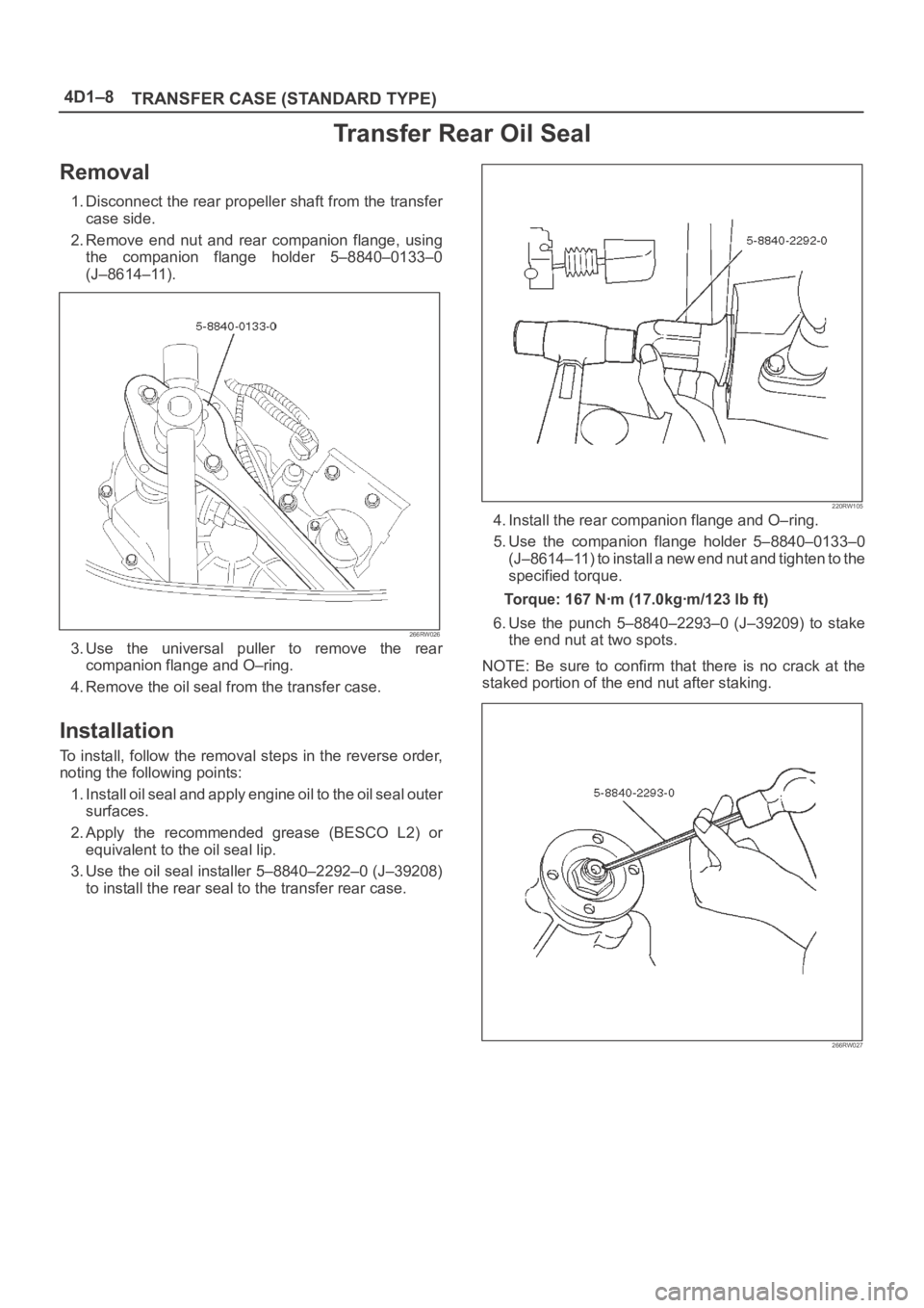
2. Remove end nut and rear companion flange, using
the companion flange holder 5–8840–0133–0
(J–8614–11).
266RW026
3. Use the universal puller to remove the rear
companion flange and O–ring.
4. Remove the oil seal from the transfer case.
Installation
To install, follow the removal steps in the reverse order,
noting the following points:
1. Install oil seal and apply engine oil to the oil seal outer
surfaces.
2. Apply the recommended grease (BESCO L2) or
equivalent to the oil seal lip.
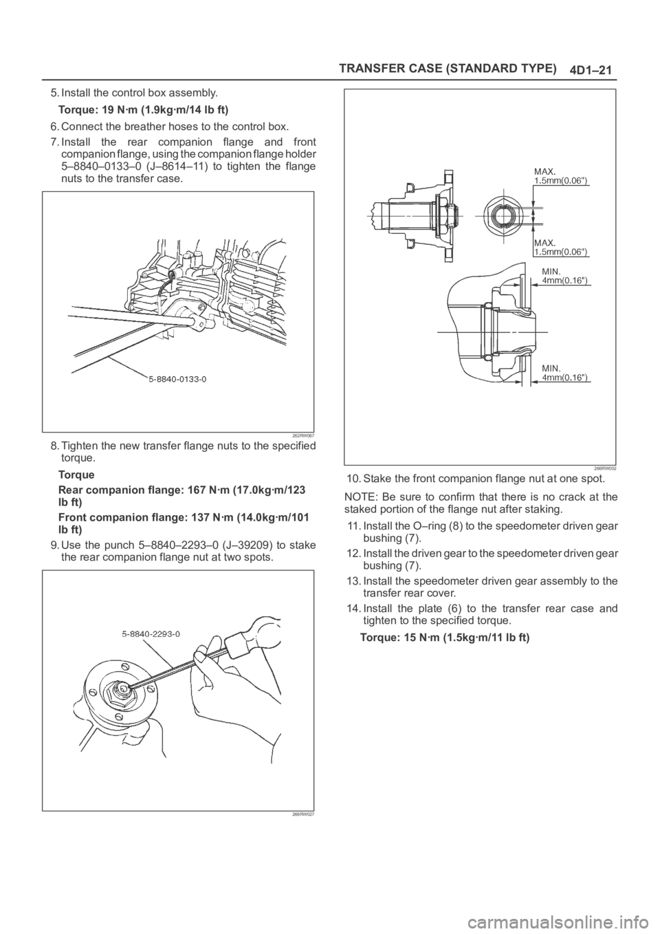
3. Use the oil seal installer 5–8840–2292–0 (J–39208)
to install the rear seal to the transfer rear case.
220RW105
4. Install the rear companion flange and O–ring.
5. Use the companion flange holder 5–8840–0133–0
(J–8614–11) to install a new end nut and tighten to the
specified torque.
Torque: 167 Nꞏm (17.0kgꞏm/123 lb ft)
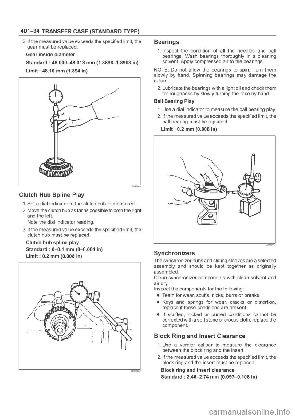
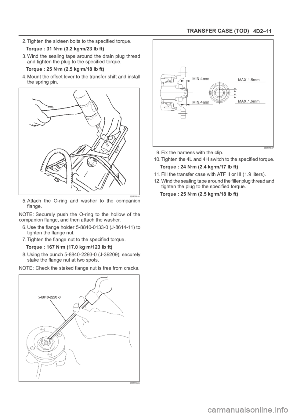
6. Use the punch 5–8840–2293–0 (J–39209) to stake
the end nut at two spots.
NOTE: Be sure to confirm that there is no crack at the
staked portion of the end nut after staking.
266RW027
Page 4276 of 6000
TRANSFER CASE (STANDARD TYPE)
4D1–15
266RW002
16. Stake the front companion flange nut at one spot.
NOTE: Be sure to confirm that there is no crack at the
staked portion of the flange nut after staking.
17. Install the O–ring (8) to the speedometer driven gear
bushing (7).
18. Install the driven gear to the speedometer driven gear
bushing (7).
19. Install the speedometer driven gear assembly to the
transfer rear cover.20. Install the plate (6) to the transfer rear case and
tighten to the specified torque.
Torque: 15 Nꞏm (1.5kgꞏm/11 lb ft)
21. Install the speedometer sensor and tighten to the
specified torque.
Torque: 27 Nꞏm (2.8kgꞏm/20 lb ft)
225RW014
Page 4282 of 6000

TRANSFER CASE (STANDARD TYPE)
4D1–21
5. Install the control box assembly.
Torque: 19 Nꞏm (1.9kgꞏm/14 lb ft)
6. Connect the breather hoses to the control box.
7. Install the rear companion flange and front
companion flange, using the companion flange holder
5–8840–0133–0 (J–8614–11) to tighten the flange
nuts to the transfer case.
262RW067
8. Tighten the new transfer flange nuts to the specified
torque.
Torque
Rear companion flange: 167 Nꞏm (17.0kgꞏm/123
lb ft)
Front companion flange: 137 Nꞏm (14.0kgꞏm/101
lb ft)
9. Use the punch 5–8840–2293–0 (J–39209) to stake
the rear companion flange nut at two spots.
266RW027
266RW002
10. Stake the front companion flange nut at one spot.
NOTE: Be sure to confirm that there is no crack at the
staked portion of the flange nut after staking.
11. Install the O–ring (8) to the speedometer driven gear
bushing (7).
12. Install the driven gear to the speedometer driven gear
bushing (7).
13. Install the speedometer driven gear assembly to the
transfer rear cover.
14. Install the plate (6) to the transfer rear case and
tighten to the specified torque.
Torque: 15 Nꞏm (1.5kgꞏm/11 lb ft)
Page 4295 of 6000

4D1–34
TRANSFER CASE (STANDARD TYPE)
2. If the measured value exceeds the specified limit, the
gear must be replaced.
Gear inside diameter
Standard : 48.000–48.013 mm (1.8898–1.8903 in)
Limit : 48.10 mm (1.894 in)
226RS040
Clutch Hub Spline Play
1. Set a dial indicator to the clutch hub to measured.
2. Move the clutch hub as far as possible to both the right
and the left.
Note the dial indicator reading.
3. If the measured value exceeds the specified limit, the
clutch hub must be replaced.
Clutch hub spline play
Standard : 0–0.1 mm (0–0.004 in)
Limit : 0.2 mm (0.008 in)
226RS042
Bearings
1. Inspect the condition of all the needles and ball
bearings. Wash bearings thoroughly in a cleaning
solvent. Apply compressed air to the bearings.
NOTE: Do not allow the bearings to spin. Turn them
slowly by hand. Spinning bearings may damage the
rollers.
2. Lubricate the bearings with a light oil and check them
for roughness by slowly turning the race by hand.
Ball Bearing Play
1. Use a dial indicator to measure the ball bearing play.
2. If the measured value exceeds the specified limit, the
ball bearing must be replaced.
Limit : 0.2 mm (0.008 in)
226RS043
Synchronizers
The synchronizer hubs and sliding sleeves are a selected
assembly and should be kept together as originally
assembled.
Clean synchronizer components with clean solvent and
air dry.
Inspect the components for the following:
Teeth for wear, scuffs, nicks, burrs or breaks.
Keys and springs for wear, cracks or distortion,
replace if these conditions are present.
If scuffed, nicked or burred conditions cannot be
corrected with a soft stone or crocus cloth, replace the
component.
Block Ring and Insert Clearance
1. Use a vernier caliper to measure the clearance
between the block ring and the insert.
2. If the measured value exceeds the specified limit, the
block ring and the insert must be replaced.
Block ring and insert clearance
Standard : 2.46–2.74 mm (0.097–0.108 in)
Page 4296 of 6000
TRANSFER CASE (STANDARD TYPE)
4D1–35
Limit : 3.0 mm (0.118 in)
226RS037
2WD–4WD 3–Cone Synchronizer (Shift On
The Fly model)
1. Use a thickness gauge to measure the clearance
between the block ring and the dog teeth.
2. If the measured value exceeds the specified limit, the
2WD–4WD synchronizer assembly must be
replaced.
Block ring and insert clearance
Standard : 1.5 mm (0.059 in)
Limit : 0.8 mm (0.031 in)
226RW142
Clutch Hub and Insert Clearance
1. Use a thickness gauge to measure the clearance
between the clutch hub and the insert.
2. If the measured value exceeds the specified limit, the
clutch hub and the insert must be replaced.
Clutch hub and insert clearance
Standard : 0.01–0.19 mm (0.0004–0.0075 in)
Limit : 0.3 mm (0.012 in)
226RS038
Detent Springs
1. Inspect the springs for distortion, cracks or wear.
Replace if these conditions are present.
Detent Spring Free Length
1. Use a vernier caliper to measure the detent spring
free length.
Page 4313 of 6000
4D2–6
TRANSFER CASE (TOD)
2. Using the oil seal installer 5-8840-2412-0 (J-42804),
install the oil seal.
NOTE: When installing the oil seal, pay attention to the
direction.
261RW051
Rear Output Shaft Oil Seal
Distance between the transfer case end and oil seal.
NOTE: When installing the oil seal to the specified
dimension, be careful not to damage it.
Distance : 9.85 — 10.35mm (0.39 — 0.41 in)
A04RW004
3. Mount the rear companion flange, O-ring , washer,
and nut to the transfer case in this order.
4. Using the flange holder 5-8840-0133-0 (J-8614-11),
install a new end nut.
Torque : 167 Nꞏm (17 kgꞏm /123 lb ft)
5. Using the punch 5-8840-2293-0 (J-39209), stake the
end nut at two spots.
NOTE: Check the staked end nut is free from cracks.
266RW028
260RW007
6. Install the rear propeller shaft to the transfer case and
tighten to the specified torque.
Torque : 63 Nꞏm (6.4 kgꞏm /46 lb ft)
Page 4314 of 6000
4D2–7 TRANSFER CASE (TOD)
TOD ECU
Removal
1. Disconnect the ground cable.
2. Move the right-hand seat forward and remove the
second seat foot rest (1).
3. Disconnect the connector from the ECU (2).
4. Remove the bolts and detach the ECU (2) from the
bracket.
F07RW021
Installation
1. Perform the removal step in reverse order.
Page 4318 of 6000

4D2–11 TRANSFER CASE (TOD)
2. Tighten the sixteen bolts to the specified torque.
Torque : 31 Nꞏm (3.2 kgꞏm/23 lb ft)
3. Wind the sealing tape around the drain plug thread
and tighten the plug to the specified torque.
Torque : 25 Nꞏm (2.5 kgꞏm/18 lb ft)
4. Mount the offset lever to the transfer shift and install
the spring pin.
261RW016
5. Attach the O-ring and washer to the companion
flange.
NOTE: Securely push the O-ring to the hollow of the
companion flange, and then attach the washer.
6. Use the flange holder 5-8840-0133-0 (J-8614-11) to
tighten the flange nut.
7. Tighten the flange nut to the specified torque.
Torque : 167 Nꞏm (17.0 kgꞏm/123 lb ft)
8. Using the punch 5-8840-2293-0 (J-39209), securely
stake the flange nut at two spots.
NOTE: Check the staked flange nut is free from cracks.
266RW028
260RW007
9. Fix the harness with the clip.
10. Tighten the 4L and 4H switch to the specified torque.
Torque : 24 Nꞏm (2.4 kgꞏm/17 lb ft)
11. Fill the transfer case with ATF II or III (1.9 liters).
12. Wind the sealing tape around the filler plug thread and
tighten the plug to the specified torque.
Torque : 25 Nꞏm (2.5 kgꞏm/18 lb ft)