Page 4559 of 6000
6A–63
ENGINE MECHANICAL
Camshaft
Camshaft and Associated Parts
014RW040
Legend
(1) Camshaft Bracket Fixing Bolt
(2) Camshaft Bracket
(3) Camshaft Assembly Intake
(4) Camshaft Assembly Exhaust
(5) Pulley Fixing Bolt(6) Camshaft Drive Gear Pulley
(7) Retainer Fixing Bolt
(8) Retainer
(9) Camshaft Drive Gear
(10) Oil Seal
Disassembly
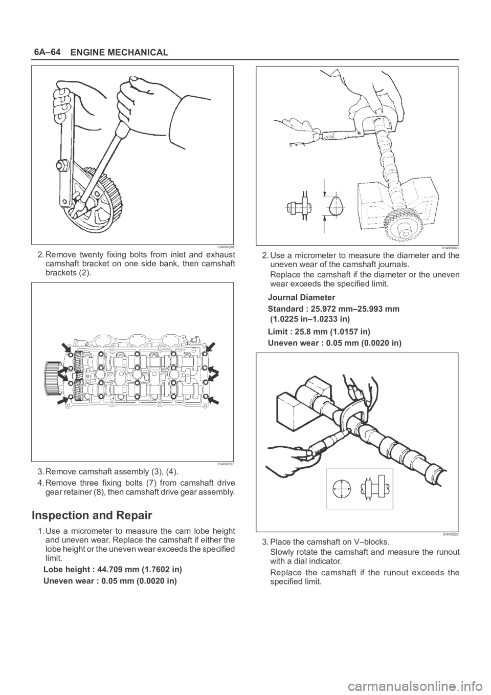
1. Remove fixing bolt (5) for camshaft drive gear pulley
using the 5–8840–2447–0 universal holder.
Page 4560 of 6000
6A–64
ENGINE MECHANICAL
014RW060
2. Remove twenty fixing bolts from inlet and exhaust
camshaft bracket on one side bank, then camshaft
brackets (2).
014RW027
3. Remove camshaft assembly (3), (4).
4. Remove three fixing bolts (7) from camshaft drive
gear retainer (8), then camshaft drive gear assembly.
Inspection and Repair
1. Use a micrometer to measure the cam lobe height
and uneven wear. Replace the camshaft if either the
lobe height or the uneven wear exceeds the specified
limit.
Lobe height : 44.709 mm (1.7602 in)
Uneven wear : 0.05 mm (0.0020 in)
014RW043
2. Use a micrometer to measure the diameter and the
uneven wear of the camshaft journals.
Replace the camshaft if the diameter or the uneven
wear exceeds the specified limit.
Journal Diameter
Standard : 25.972 mm–25.993 mm
(1.0225 in–1.0233 in)
Limit : 25.8 mm (1.0157 in)
Uneven wear : 0.05 mm (0.0020 in)
014RS023
3. Place the camshaft on V–blocks.
Slowly rotate the camshaft and measure the runout
with a dial indicator.
Replace the camshaft if the runout exceeds the
specified limit.
Page 4561 of 6000
6A–65
ENGINE MECHANICAL
Runout
Limit : 0.1 mm (0.0039 in)
014RW044
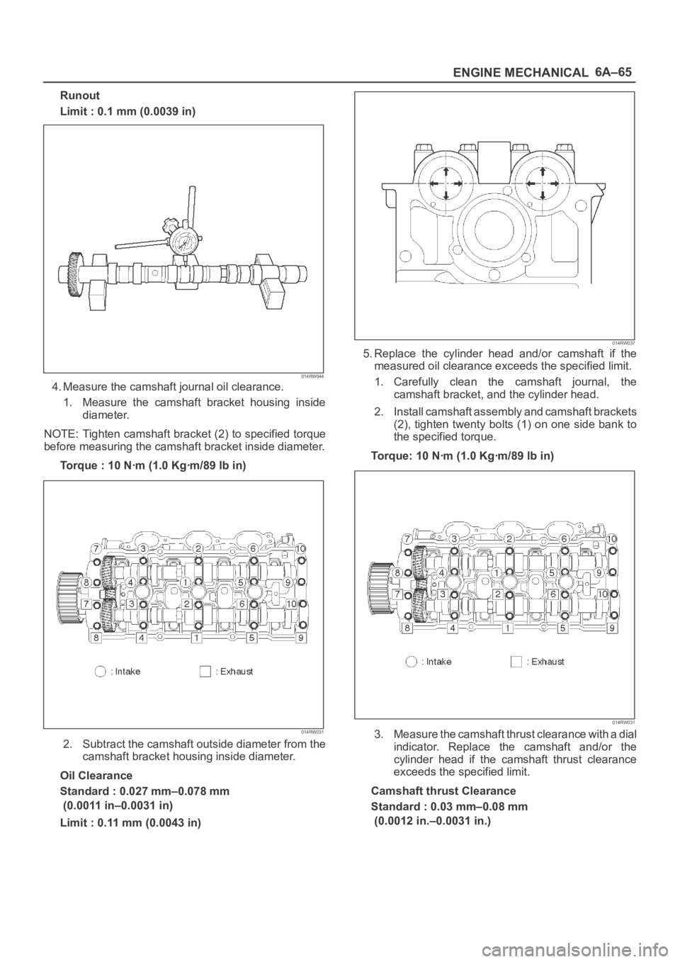
4. Measure the camshaft journal oil clearance.
1. Measure the camshaft bracket housing inside
diameter.
NOTE: Tighten camshaft bracket (2) to specified torque
before measuring the camshaft bracket inside diameter.
Torque : 10 Nꞏm (1.0 Kgꞏm/89 lb in)
014RW031
2. Subtract the camshaft outside diameter from the
camshaft bracket housing inside diameter.
Oil Clearance
Standard : 0.027 mm–0.078 mm
(0.0011 in–0.0031 in)
Limit : 0.11 mm (0.0043 in)
014RW037
5. Replace the cylinder head and/or camshaft if the
measured oil clearance exceeds the specified limit.
1. Carefully clean the camshaft journal, the
camshaft bracket, and the cylinder head.
2. Install camshaft assembly and camshaft brackets
(2), tighten twenty bolts (1) on one side bank to
the specified torque.
Torque: 10 Nꞏm (1.0 Kgꞏm/89 lb in)
014RW031
3. Measure the camshaft thrust clearance with a dial
indicator. Replace the camshaft and/or the
cylinder head if the camshaft thrust clearance
exceeds the specified limit.
Camshaft thrust Clearance
Standard : 0.03 mm–0.08 mm
(0.0012 in.–0.0031 in.)
Page 4562 of 6000
6A–66
ENGINE MECHANICAL
Limit : 0.12 mm (0.0047 mm)
014RW035
Reassembly
1. Install camshaft drive gear assembly and tighten
three bolts to specified torque.
Torque: 10 Nꞏm (1.0 Kgꞏm/89 lb in)
2. Tighten sub gear setting bolt.
1. Use 5–8840–2443–0 to turn sub gear to right
direction until the M5 bolt hole aligns between
camshaft driven gear and sub gear.
2. Tighten M5 bolt suitable torque for prevent
moving the sub gear.
014RW041
3. Install camshaft assembly and camshaft brackets,
tighten twenty bolts on one side bank to the specified
torque.
1. Apply engine oil to camshaft journal and bearing
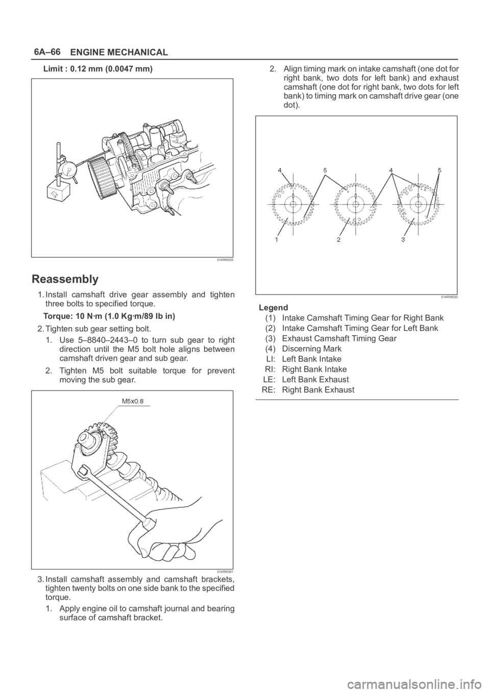
surface of camshaft bracket.2. Align timing mark on intake camshaft (one dot for
right bank, two dots for left bank) and exhaust
camshaft (one dot for right bank, two dots for left
bank) to timing mark on camshaft drive gear (one
dot).
014RW020
Legend
(1) Intake Camshaft Timing Gear for Right Bank
(2) Intake Camshaft Timing Gear for Left Bank
(3) Exhaust Camshaft Timing Gear
(4) Discerning Mark
LI: Left Bank Intake
RI: Right Bank Intake
LE: Left Bank Exhaust
RE: Right Bank Exhaust
Page 4574 of 6000
6A–78
ENGINE MECHANICAL
015RS031
Remove any ridge or carbon build up from the top
end of the cylinder.
9. Remove the piston rings (8) with a piston ring
expander. Arrange the removed piston rings in the
cylinder number order.
015RS022
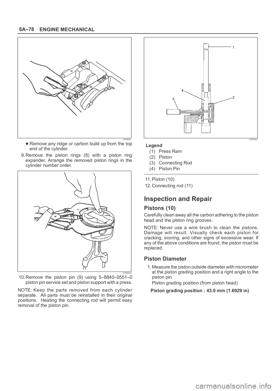
10. Remove the piston pin (9) using 5–8840–0551–0
piston pin service set and piston support with a press.
NOTE: Keep the parts removed from each cylinder
separate. All parts must be reinstalled in their original
positions. Heating the connecting rod will permit easy
removal of the piston pin.
015RX001
Legend
(1) Press Ram
(2) Piston
(3) Connecting Rod
(4) Piston Pin
11. Piston (10)
12. Connecting rod (11)
Inspection and Repair
Pistons (10)
Carefully clean away all the carbon adhering to the piston
head and the piston ring grooves.
NOTE: Never use a wire brush to clean the pistons.
Damage will result. Visually check each piston for
cracking, scoring, and other signs of excessive wear. If
any of the above conditions are found, the piston must be
replaced.
Piston Diameter
1. Measure the piston outside diameter with micrometer
at the piston grading position and a right angle to the
piston pin.
Piston grading position (from piston head)
Piston grading position : 43.0 mm (1.6929 in)
Page 4582 of 6000
6A–86
ENGINE MECHANICAL
11. Remove rear oil seal retainer assembly.
12. Remove main bearing cap.
13. Remove crankshaft.
14. Remove cylinder block.
Inspection and Repair
1. Remove the cylinder head gasket and any other
material adhering to the upper surface of the cylinder
block. Be very careful not to allow any material to
accidentally drop into the cylinder block. Be very
careful not to scratch the cylinder block.
2. Carefully remove the oil pump, rear oil seal retainer,
and crankcase assembly installation surface seal.
3. Wipe the cylinder block clean.
4. Visually inspect the cylinder block. If necessary, use a
flaw detector to perform a dye penetrate and
hydraulic (or air pressure) test. If cracking or other
damage is discovered, the cylinder block must either
be repaired or replaced.
Flatness
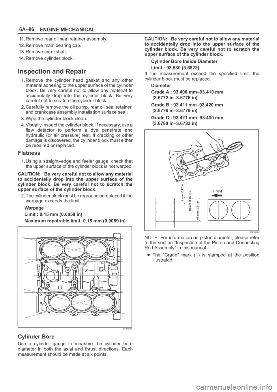
1. Using a straight–edge and feeler gauge, check that
the upper surface of the cylinder block is not warped.
CAUTION: Be very careful not to allow any material
to accidentally drop into the upper surface of the
cylinder block. Be very careful not to scratch the
upper surface of the cylinder block.
2. The cylinder block must be reground or replaced if the
warpage exceeds the limit.
Warpage
Limit : 0.15 mm (0.0059 in)
Maximum repairable limit: 0.15 mm (0.0059 in)
012RS004
Cylinder Bore
Use a cylinder gauge to measure the cylinder bore
diameter in both the axial and thrust directions. Each
measurement should be made at six points.CAUTION: Be very careful not to allow any material
to accidentally drop into the upper surface of the
cylinder block. Be very careful not to scratch the
upper surface of the cylinder block.
Cylinder Bore Inside Diameter
Limit : 93.530 (3.6823)
If the measurement exceed the specified limit, the
cylinder block must be replaced.
Diameter
Grade A : 93.400 mm–93.410 mm
(3.6772 in–3.6776 in)
Grade B : 93.411 mm–93.420 mm
(3.6776 in–3.6779 in)
Grade C : 93.421 mm–93.430 mm
(3.6780 in–3.6783 in)
012RS005
NOTE: For information on piston diameter, please refer
to the section ”Inspection of the Piston and Connecting
Rod Assembly” in this manual.
The ”Grade” mark (1) is stamped at the position
illustrated.
Page 4588 of 6000
6A–92
ENGINE MECHANICAL
Cylinder head cover, Cylinder head, Camshaft bracket, Common chamber, EGR valve and EGR pipe
Nꞏm (Kgꞏm/Ib ft)
E06RW043
Page 4600 of 6000
ENGINE COOLING6B–7
Water Pump
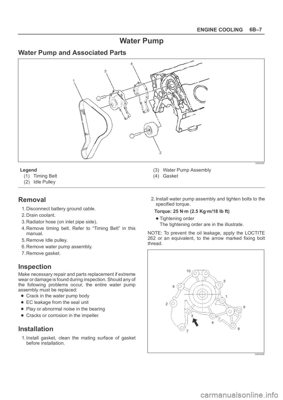
Water Pump and Associated Parts
030RS002
Legend
(1) Timing Belt
(2) Idle Pulley(3) Water Pump Assembly
(4) Gasket
Removal
1. Disconnect battery ground cable.
2. Drain coolant.
3. Radiator hose (on inlet pipe side).
4. Remove timing belt. Refer to “Timing Belt” in this
manual.
5. Remove Idle pulley.
6. Remove water pump assembly.
7. Remove gasket.
Inspection
Make necessary repair and parts replacement if extreme
wear or damage is found during inspection. Should any of
the following problems occur, the entire water pump
assembly must be replaced:
Crack in the water pump body
EC leakage from the seal unit
Play or abnormal noise in the bearing
Cracks or corrosion in the impeller.
Installation
1. Install gasket, clean the mating surface of gasket
before installation.2. Install water pump assembly and tighten bolts to the
specified torque.
Torque: 25 Nꞏm (2.5 Kgꞏm/18 lb ft)
Tightening order
The tightening order are in the illustrate.
NOTE: To prevent the oil leakage, apply the LOCTITE
262 or an equivalent, to the arrow marked fixing bolt
thread.
030RW008