1998 OPEL FRONTERA rack
[x] Cancel search: rackPage 4334 of 6000
4D2–27 TRANSFER CASE (TOD)
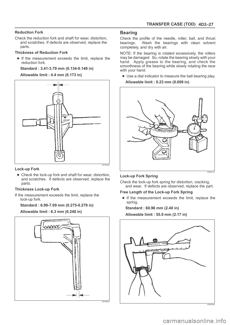
Reduction Fork
Check the reduction fork and shaft for wear, distortion,
and scratches. If defects are observed, replace the
parts.
Thickness of Reduction Fork
If the measurement exceeds the limit, replace the
reduction fork.
Standard : 3.41-3.79 mm (0.134-0.149 in)
Allowable limit : 4.4 mm (0.173 in)
261RW026
Lock-up Fork
Check the lock-up fork and shaft for wear, distortion,
and scratches. If defects are observed, replace the
parts.
Thickness Lock-up Fork
If the measurement exceeds the limit, replace the
lock-up fork.
Standard : 6.99-7.09 mm (0.275-0.279 in)
Allowable limit : 6.3 mm (0.248 in)
261RW027
Bearing
Check the profile of the needle, roller, ball, and thrust
bearings. Wash the bearings with clean solvent
completely, and dry with air.
NOTE: If the bearing is rotated excessively, the rollers
may be damaged. So, rotate the bearing slowly with your
hand. Apply grease to the bearing, and check the
smoothness of the bearing while slowly rotating the race
with your hand.
Use a dial indicator to measure the ball bearing play.
Allowable limit : 0.23 mm (0.009 in)
226RW143
Lock-up Fork Spring
Check the lock-up fork spring for distortion, cracking,
and wear. If defects are observed, replace the part.
Free Length of the Lock-up Fork Spring
If the measurement exceeds the limit, replace the
spring.
Standard : 60.96 mm (2.40 in)
Allowable limit : 55.0 mm (2.17 in)
220RW045
Page 4395 of 6000
5A–45 BRAKE CONTROL SYSTEM
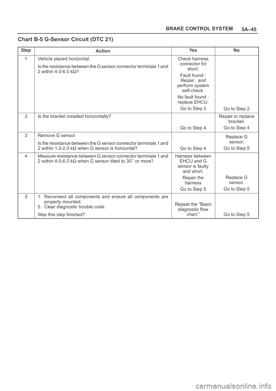
Chart B-5 G-Sensor Circuit (DTC 21)
StepActionYe sNo
1Vehicle placed horizontal.
Is the resistance between the G sensor connector terminals 1 and
2 within 4.0-6.0 k
?
Check harness
connector for
short.
Fault found :
Repair , and
perform system
self-check.
No fault found :
replace EHCU.
Go to Step 3
Go to Step 2
2Is the bracket installed horizontally?
Go to Step 4
Repair or replace
bracket.
Go to Step 4
3Remove G sensor.
Is the resistance between the G sensor connector terminals 1 and
2 within 1.0-2.0 k
when G sensor is horizontal?Go to Step 4
Replace G
sensor.
Go to Step 5
4Measure resistance between G sensor connector terminals 1 and
2 within 4.0-6.0 k
when G sensor tilted to 30 or more?
Harness between
EHCU and G
sensor is faulty
and short.
Repair the
harness
Go to Step 5
Replace G
sensor.
Go to Step 5
51. Reconnect all components and ensure all components are
properly mounted.
2. Clear diagnostic trouble code.
Was this step finished?
Repeat the “Basic
diagnostic flow
chart.”
Go to Step 5
Page 4416 of 6000
5B–4ANTI–LOCK BRAKE SYSTEM
Front Wheel Speed Sensor
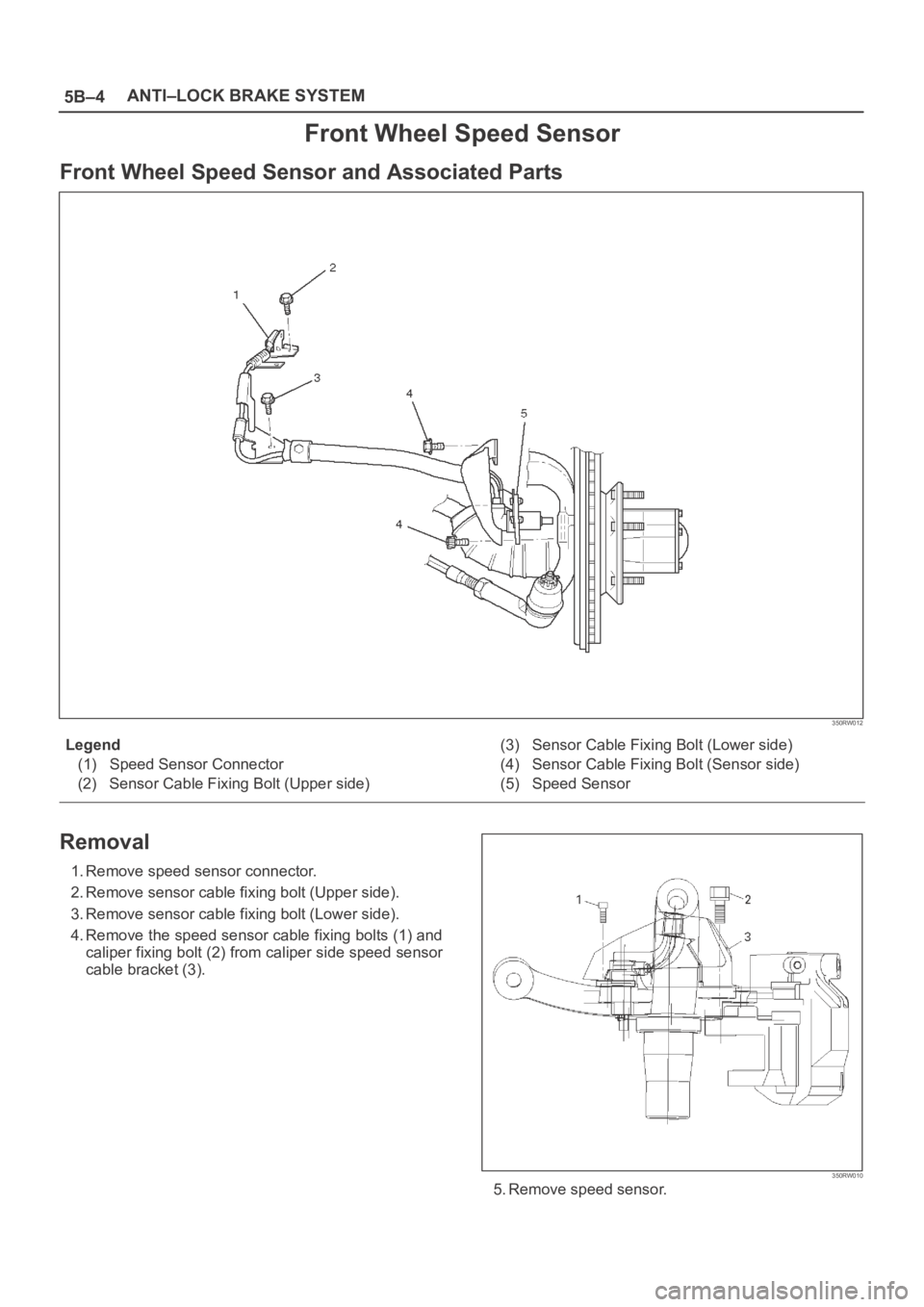
Front Wheel Speed Sensor and Associated Parts
350RW012
Legend
(1) Speed Sensor Connector
(2) Sensor Cable Fixing Bolt (Upper side)(3) Sensor Cable Fixing Bolt (Lower side)
(4) Sensor Cable Fixing Bolt (Sensor side)
(5) Speed Sensor
Removal
1. Remove speed sensor connector.
2. Remove sensor cable fixing bolt (Upper side).
3. Remove sensor cable fixing bolt (Lower side).
4. Remove the speed sensor cable fixing bolts (1) and
caliper fixing bolt (2) from caliper side speed sensor
cable bracket (3).
350RW010
5. Remove speed sensor.
Page 4417 of 6000
5B–5 ANTI–LOCK BRAKE SYSTEM
Inspection and Repair
1. Check the speed sensor pole piece for presence of
foreign materials; remove any dirt, etc.
2. Check the pole piece for damage; replace speed
sensor if necessary.
3. Check the speed sensor cable for short or open
circuit, and replace with a new one if necessary.
To check for cable short or open, bend or stretch the
cable while checking for continuity.
4. Check the sensor ring for damage including tooth
chipping, and if damaged, replace the sensor ring
assembly. Refer to Front Hub and Disc in Drive Shaft
System section.
Installation
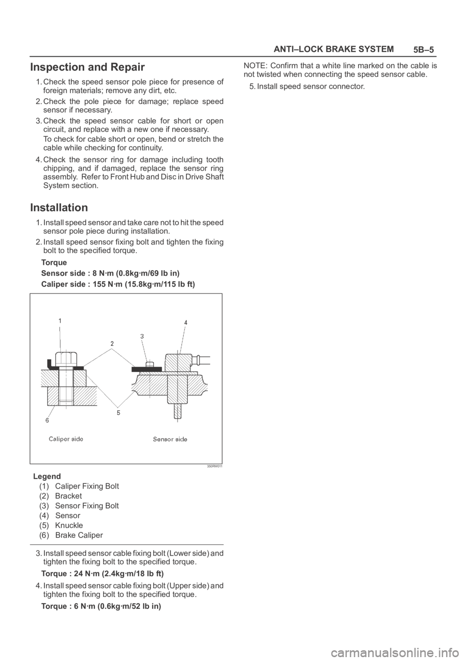
1. Install speed sensor and take care not to hit the speed
sensor pole piece during installation.
2. Install speed sensor fixing bolt and tighten the fixing
bolt to the specified torque.
Torque
Sensor side : 8 Nꞏm (0.8kgꞏm/69 lb in)
Caliper side : 155 Nꞏm (15.8kgꞏm/115 lb ft)
350RW011
Legend
(1) Caliper Fixing Bolt
(2) Bracket
(3) Sensor Fixing Bolt
(4) Sensor
(5) Knuckle
(6) Brake Caliper
3. Install speed sensor cable fixing bolt (Lower side) and
tighten the fixing bolt to the specified torque.
Torque : 24 Nꞏm (2.4kgꞏm/18 lb ft)
4. Install speed sensor cable fixing bolt (Upper side) and
tighten the fixing bolt to the specified torque.
Torque : 6 Nꞏm (0.6kgꞏm/52 lb in)NOTE: Confirm that a white line marked on the cable is
not twisted when connecting the speed sensor cable.
5. Install speed sensor connector.
Page 4510 of 6000
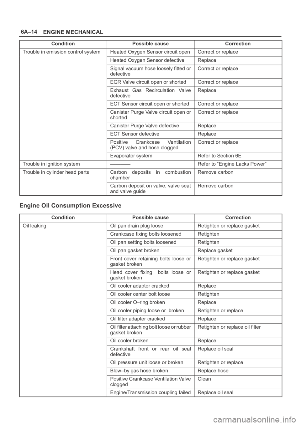
6A–14
ENGINE MECHANICAL
Condition CorrectionPossible cause
Trouble in emission control systemHeated Oxygen Sensor circuit openCorrect or replace
Heated Oxygen Sensor defectiveReplace
Signal vacuum hose loosely fitted or
defectiveCorrect or replace
EGR Valve circuit open or shortedCorrect or replace
Exhaust Gas Recirculation Valve
defectiveReplace
ECT Sensor circuit open or shortedCorrect or replace
Canister Purge Valve circuit open or
shortedCorrect or replace
Canister Purge Valve defectiveReplace
ECT Sensor defectiveReplace
Positive Crankcase Ventilation
(PCV) valve and hose cloggedCorrect or replace
Evaporator systemRefer to Section 6E
Trouble in ignition system————Refer to “Engine Lacks Power”
Trouble in cylinder head partsCarbon deposits in combustion
chamberRemove carbon
Carbon deposit on valve, valve seat
and valve guideRemove carbon
Engine Oil Consumption Excessive
ConditionPossible causeCorrection
Oil leakingOil pan drain plug looseRetighten or replace gasket
Crankcase fixing bolts loosenedRetighten
Oil pan setting bolts loosenedRetighten
Oil pan gasket brokenReplace gasket
Front cover retaining bolts loose or
gasket brokenRetighten or replace gasket
Head cover fixing bolts loose or
gasket brokenRetighten or replace gasket
Oil cooler adapter crackedReplace
Oil cooler center bolt looseRetighten
Oil cooler O–ring brokenReplace
Oil cooler piping loose or brokenRetighten or replace
Oil filter adapter crackedReplace
Oil filter attaching bolt loose or rubber
gasket brokenRetighten or replace oil filter
Oil cooler brokenReplace
Crankshaft front or rear oil seal
defectiveReplace oil seal
Oil pressure unit loose or brokenRetighten or replace
Blow–by gas hose brokenReplace hose
Positive Crankcase Ventilation Valve
cloggedClean
Engine/Transmission coupling failedReplace oil seal
Page 4515 of 6000
6A–19
ENGINE MECHANICAL
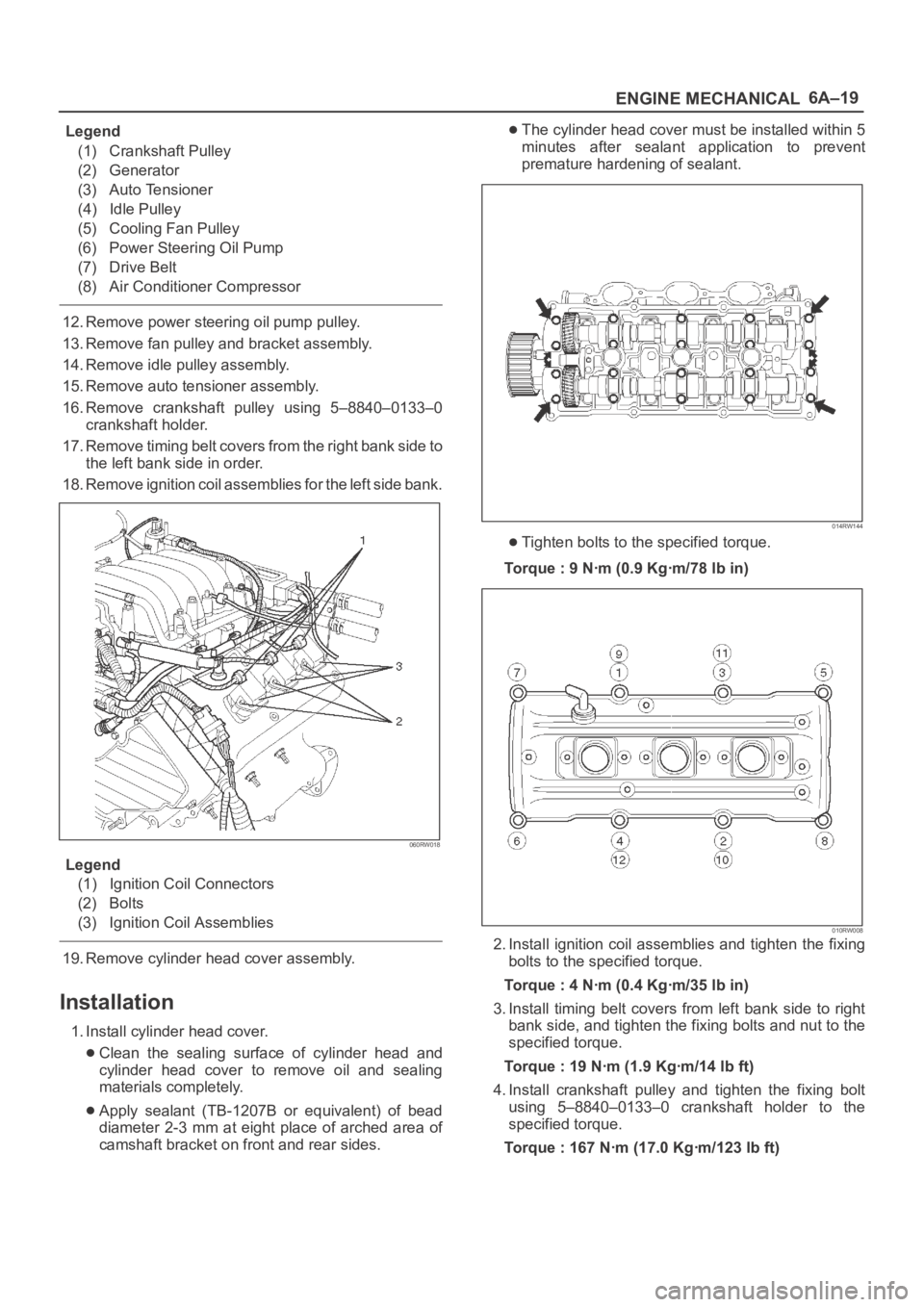
Legend
(1) Crankshaft Pulley
(2) Generator
(3) Auto Tensioner
(4) Idle Pulley
(5) Cooling Fan Pulley
(6) Power Steering Oil Pump
(7) Drive Belt
(8) Air Conditioner Compressor
12. Remove power steering oil pump pulley.
13. Remove fan pulley and bracket assembly.
14. Remove idle pulley assembly.
15. Remove auto tensioner assembly.
16. Remove crankshaft pulley using 5–8840–0133–0
crankshaft holder.
17. Remove timing belt covers from the right bank side to
the left bank side in order.
18. Remove ignition coil assemblies for the left side bank.
060RW018
Legend
(1) Ignition Coil Connectors
(2) Bolts
(3) Ignition Coil Assemblies
19. Remove cylinder head cover assembly.
Installation
1. Install cylinder head cover.
Clean the sealing surface of cylinder head and
cylinder head cover to remove oil and sealing
materials completely.
Apply sealant (TB-1207B or equivalent) of bead
diameter 2-3 mm at eight place of arched area of
camshaft bracket on front and rear sides.
The cylinder head cover must be installed within 5
minutes after sealant application to prevent
premature hardening of sealant.
014RW144
Tighten bolts to the specified torque.
Torque : 9 Nꞏm (0.9 Kgꞏm/78 lb in)
010RW008
2. Install ignition coil assemblies and tighten the fixing
bolts to the specified torque.
Torque : 4 Nꞏm (0.4 Kgꞏm/35 lb in)
3. Install timing belt covers from left bank side to right
bank side, and tighten the fixing bolts and nut to the
specified torque.
Torque : 19 Nꞏm (1.9 Kgꞏm/14 lb ft)
4. Install crankshaft pulley and tighten the fixing bolt
using 5–8840–0133–0 crankshaft holder to the
specified torque.
Torque : 167 Nꞏm (17.0 Kgꞏm/123 lb ft)
Page 4516 of 6000
6A–20
ENGINE MECHANICAL
5. Install auto tensioner assembly and tighten the fixing
bolts to the specified torque.
Torque :
Shorter Bolt : 20 Nꞏm (2.0 Kgꞏm/14 lb ft)
Longer Bolt : 39 Nꞏm (4.0 Kgꞏm/29 lb ft)
6. Install idle pulley and bracket assembly and tighten
the fixing bolt to the specified torque.
Torque : 52 Nꞏm (5.3 Kgꞏm/38 lb ft)
7. Install fan pulley and bracket assembly and tighten
the fixing bolts and nut to the specified torque.
Torque : 22 Nꞏm (2.2 Kgꞏm/16 lb ft)
8. Install power steering oil pump pulley and tighten the
fixing bolt to the specified torque.
Torque : 78 Nꞏm (8.0 Kgꞏm/58 lb ft)
9. Install drive belt by pushing down the auto tensioner
using spanner as shown in the removal step of drive
belt.
10. Install cooling fan and clutch assembly and tighten
the fixing bolts to the specified torque.
Torque : 10 Nꞏm (1.0 Kgꞏm/87 lb in)
11. Install upper fan guide and clip both side and tighten
the fixing bolts to the specified torque.
Torque : 4 Nꞏm (0.4 Kgꞏm/35 lb in)
12. Install engine harness and tighten the fixing bolts of
the retaining clip and bracket to the specified torque.
Torque : 4 Nꞏm (0.4 Kgꞏm/35 lb in)
13. Connect radiator upper and lower hoses and clip
them securely.
14. Connect vacuum hoses of those which were
disconnected in the removal step.
15. Connect wiring connectors and bonding cable of
those which were disconnected in the removal step.
16. Install air cleaner element and air cleaner duct
assembly, and clip the both end securely.
17. Connect MAF sensor connector, IAT sensor
connector and PCV hose.
18. Install engine cover mating with the dowels.
Page 4517 of 6000
6A–21
ENGINE MECHANICAL
Cylinder Head Cover RH
Removal
1. Disconnect battery ground cable.
2. Remove battery from the vehicle.
3. Drain engine coolant from faucet bottom of radiator.
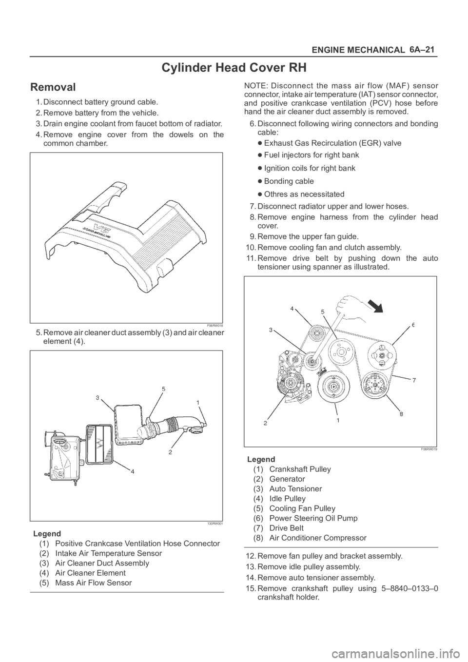
4. Remove engine cover from the dowels on the
common chamber.
F06RW018
5. Remove air cleaner duct assembly (3) and air cleaner
element (4).
130RW001
Legend
(1) Positive Crankcase Ventilation Hose Connector
(2) Intake Air Temperature Sensor
(3) Air Cleaner Duct Assembly
(4) Air Cleaner Element
(5) Mass Air Flow Sensor
NOTE: Disconnect the mass air flow (MAF) sensor
connector, intake air temperature (IAT) sensor connector,
and positive crankcase ventilation (PCV) hose before
hand the air cleaner duct assembly is removed.
6. Disconnect following wiring connectors and bonding
cable:
Exhaust Gas Recirculation (EGR) valve
Fuel injectors for right bank
Ignition coils for right bank
Bonding cable
Othres as necessitated
7. Disconnect radiator upper and lower hoses.
8. Remove engine harness from the cylinder head
cover.
9. Remove the upper fan guide.
10. Remove cooling fan and clutch assembly.
11. Remove drive belt by pushing down the auto
tensioner using spanner as illustrated.
F06RW019
Legend
(1) Crankshaft Pulley
(2) Generator
(3) Auto Tensioner
(4) Idle Pulley
(5) Cooling Fan Pulley
(6) Power Steering Oil Pump
(7) Drive Belt
(8) Air Conditioner Compressor
12. Remove fan pulley and bracket assembly.
13. Remove idle pulley assembly.
14. Remove auto tensioner assembly.
15. Remove crankshaft pulley using 5–8840–0133–0
crankshaft holder.