1998 OPEL FRONTERA rack
[x] Cancel search: rackPage 2535 of 6000
7C–26CLUTCH
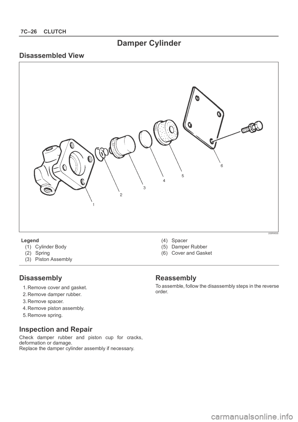
Damper Cylinder
Disassembled View
205RW005
Legend
(1) Cylinder Body
(2) Spring
(3) Piston Assembly(4) Spacer
(5) Damper Rubber
(6) Cover and Gasket
Disassembly
1. Remove cover and gasket.
2. Remove damper rubber.
3. Remove spacer.
4. Remove piston assembly.
5. Remove spring.
Inspection and Repair
Check damper rubber and piston cup for cracks,
deformation or damage.
Replace the damper cylinder assembly if necessary.
Reassembly
To assemble, follow the disassembly steps in the reverse
order.
Page 2543 of 6000
8A–4LIGHTING SYSTEM
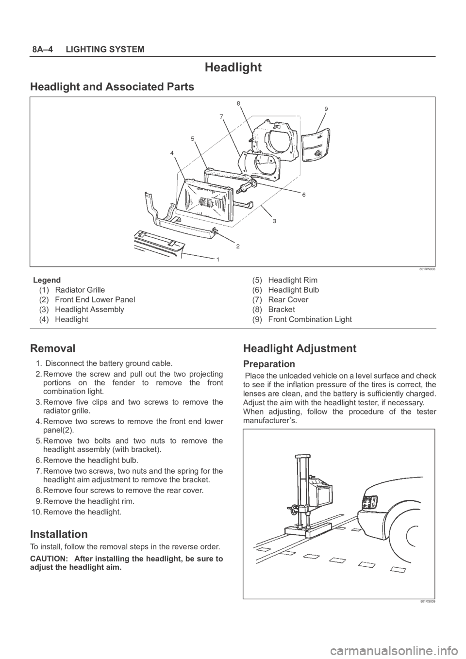
Headlight
Headlight and Associated Parts
801RW003
Legend
(1) Radiator Grille
(2) Front End Lower Panel
(3) Headlight Assembly
(4) Headlight(5) Headlight Rim
(6) Headlight Bulb
(7) Rear Cover
(8) Bracket
(9) Front Combination Light
Removal
1. Disconnect the battery ground cable.
2. Remove the screw and pull out the two projecting
portions on the fender to remove the front
combination light.
3. Remove five clips and two screws to remove the
radiator grille.
4. Remove two screws to remove the front end lower
panel(2).
5. Remove two bolts and two nuts to remove the
headlight assembly (with bracket).
6. Remove the headlight bulb.
7. Remove two screws, two nuts and the spring for the
headlight aim adjustment to remove the bracket.
8. Remove four screws to remove the rear cover.
9. Remove the headlight rim.
10. Remove the headlight.
Installation
To install, follow the removal steps in the reverse order.
CAUTION: After installing the headlight, be sure to
adjust the headlight aim.
Headlight Adjustment
Preparation
Place the unloaded vehicle on a level surface and check
to see if the inflation pressure of the tires is correct, the
lenses are clean, and the battery is sufficiently charged.
Adjust the aim with the headlight tester, if necessary.
When adjusting, follow the procedure of the tester
manufacturer’s.
801RS009
Page 2545 of 6000
8A–6LIGHTING SYSTEM
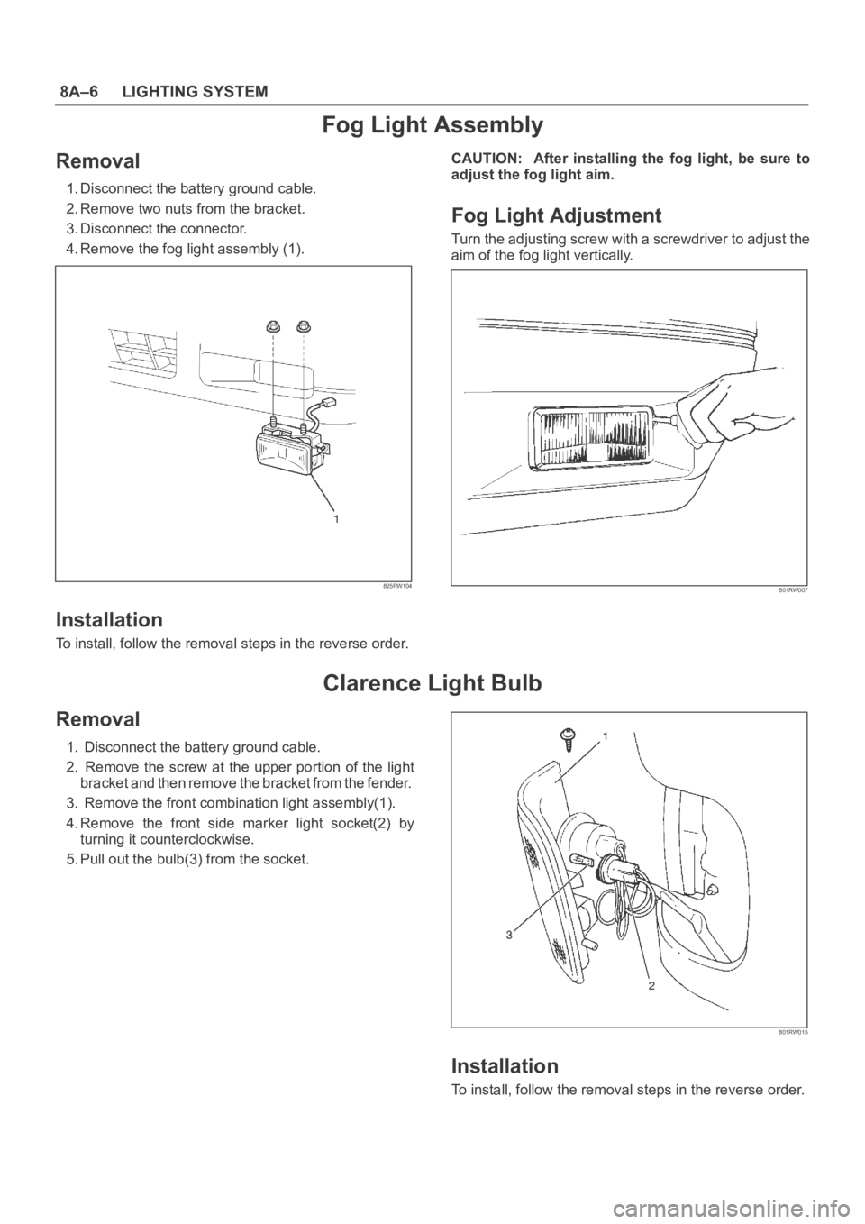
Fog Light Assembly
Removal
1. Disconnect the battery ground cable.
2. Remove two nuts from the bracket.
3. Disconnect the connector.
4. Remove the fog light assembly (1).
825RW104
Installation
To install, follow the removal steps in the reverse order.CAUTION: After installing the fog light, be sure to
adjust the fog light aim.
Fog Light Adjustment
Turn the adjusting screw with a screwdriver to adjust the
aim of the fog light vertically.
801RW007
Clarence Light Bulb
Removal
1. Disconnect the battery ground cable.
2. Remove the screw at the upper portion of the light
bracket and then remove the bracket from the fender.
3. Remove the front combination light assembly(1).
4. Remove the front side marker light socket(2) by
turning it counterclockwise.
5. Pull out the bulb(3) from the socket.
801RW015
Installation
To install, follow the removal steps in the reverse order.
Page 2549 of 6000
8A–10LIGHTING SYSTEM
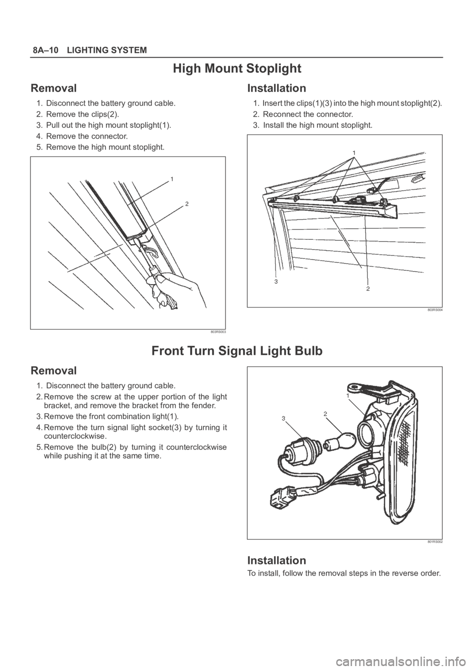
High Mount Stoplight
Removal
1. Disconnect the battery ground cable.
2. Remove the clips(2).
3. Pull out the high mount stoplight(1).
4. Remove the connector.
5. Remove the high mount stoplight.
803RS003
Installation
1. Insert the clips(1)(3) into the high mount stoplight(2).
2. Reconnect the connector.
3. Install the high mount stoplight.
803RS004
Front Turn Signal Light Bulb
Removal
1. Disconnect the battery ground cable.
2. Remove the screw at the upper portion of the light
bracket, and remove the bracket from the fender.
3. Remove the front combination light(1).
4. Remove the turn signal light socket(3) by turning it
counterclockwise.
5. Remove the bulb(2) by turning it counterclockwise
while pushing it at the same time.
801RS002
Installation
To install, follow the removal steps in the reverse order.
Page 2587 of 6000
8C–4ENTERTAINMENT
Rod Type Antenna
Removal
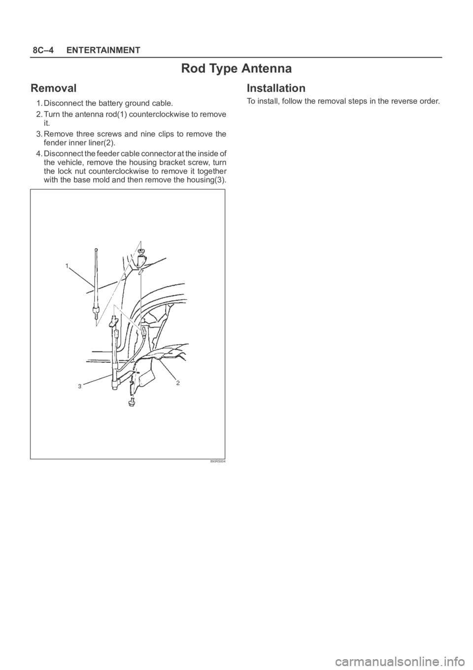
1. Disconnect the battery ground cable.
2. Turn the antenna rod(1) counterclockwise to remove
it.
3. Remove three screws and nine clips to remove the
fender inner liner(2).
4. Disconnect the feeder cable connector at the inside of
the vehicle, remove the housing bracket screw, turn
the lock nut counterclockwise to remove it together
with the base mold and then remove the housing(3).
890RS004
Installation
To install, follow the removal steps in the reverse order.
Page 2588 of 6000
ENTERTAINMENT8C–5
Auto Antenna
General Description
The auto antenna is interlocked with the radio switch. The
antenna rod goes up when the switch is on, and goes
down when the switch is off. The antenna rod also goes
down when the starter switch is turned off with the radio
on.
The antenna rod goes up or down when the cable
connected to the uppermost rod is let out or taken up by
the rotation of motor.
The motor is provided with a built-in limit switch. When the
up/down motion of the antenna is completed, the limit
switch is activated to cut off the circuit.
Removal
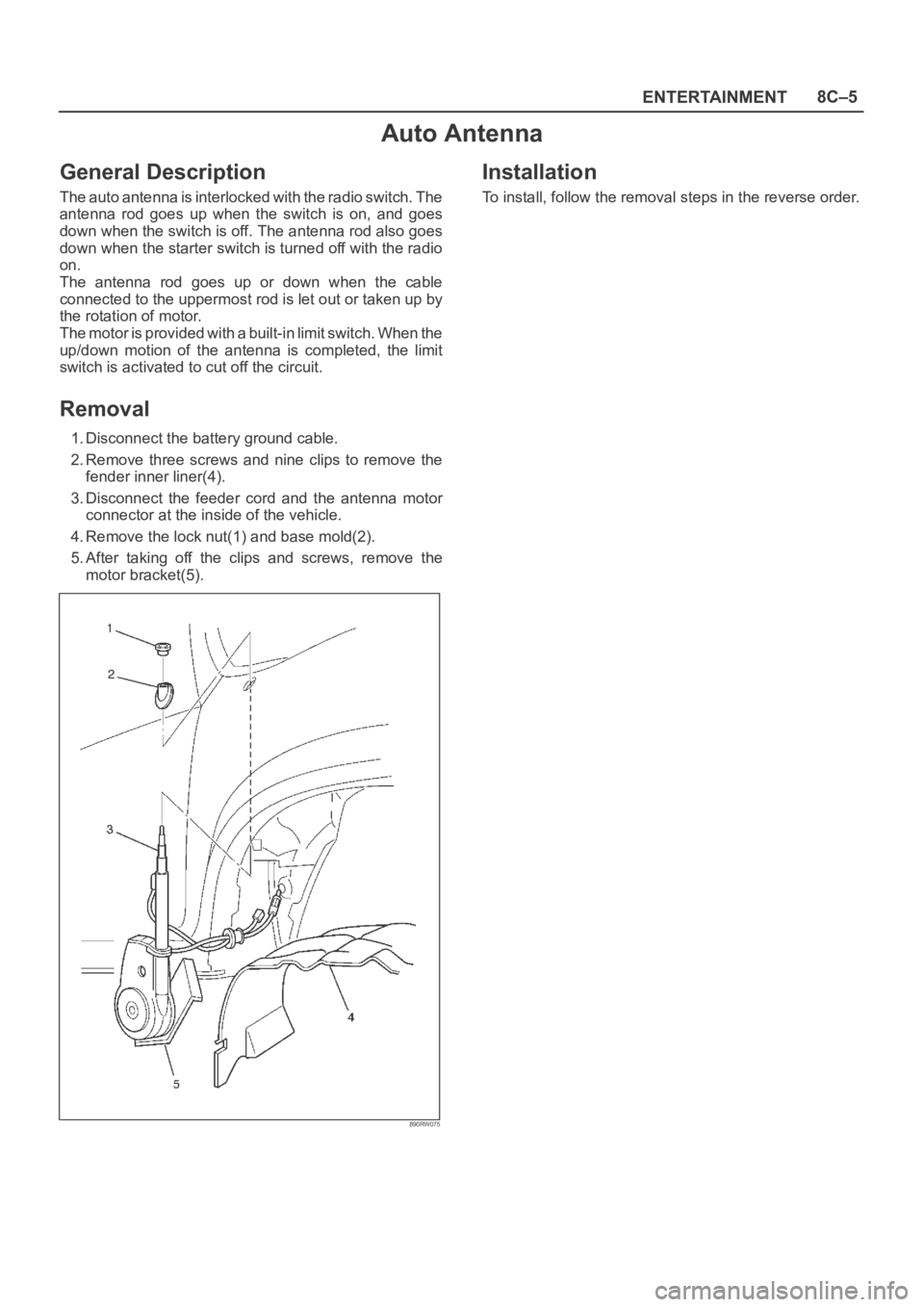
1. Disconnect the battery ground cable.
2. Remove three screws and nine clips to remove the
fender inner liner(4).
3. Disconnect the feeder cord and the antenna motor
connector at the inside of the vehicle.
4. Remove the lock nut(1) and base mold(2).
5. After taking off the clips and screws, remove the
motor bracket(5).
890RW075
Installation
To install, follow the removal steps in the reverse order.
Page 3196 of 6000
8F–1 BODY STRUCTURE
BODY AND ACCESSORIES
BODY STRUCTURE
CONTENTS
Service Precaution 8F–3. . . . . . . . . . . . . . . . . . . . . .
Frame 8F–3. . . . . . . . . . . . . . . . . . . . . . . . . . . . . . . . .
General Description 8F–3. . . . . . . . . . . . . . . . . . . . . .
Frame Dimensions (L W B) 8F–4. . . . . . . . . . . . . . .
Frame Dimensions (S W B) 8F–5. . . . . . . . . . . . . . .
General Description 8F–6. . . . . . . . . . . . . . . . . . . . .
Front Bumper 8F–6. . . . . . . . . . . . . . . . . . . . . . . . . . .
Parts Location 8F–6. . . . . . . . . . . . . . . . . . . . . . . .
Removal 8F–7. . . . . . . . . . . . . . . . . . . . . . . . . . . . .
Installation 8F–7. . . . . . . . . . . . . . . . . . . . . . . . . . . .
Front Bumper Slider Bracket 8F–7. . . . . . . . . . . . . .
Removal 8F–7. . . . . . . . . . . . . . . . . . . . . . . . . . . . .
Installation 8F–7. . . . . . . . . . . . . . . . . . . . . . . . . . . .
Rear Bumper 8F–8. . . . . . . . . . . . . . . . . . . . . . . . . . .
Parts Location 8F–8. . . . . . . . . . . . . . . . . . . . . . . .
Removal 8F–8. . . . . . . . . . . . . . . . . . . . . . . . . . . . .
Installation 8F–9. . . . . . . . . . . . . . . . . . . . . . . . . . . .
Parts Location (W/Rear Combination Light
and License Light) 8F–10. . . . . . . . . . . . . . . . . . . .
Removal 8F–10. . . . . . . . . . . . . . . . . . . . . . . . . . . . .
Installation 8F–11. . . . . . . . . . . . . . . . . . . . . . . . . . . .
Parts Location (W/Rear Combination Light) 8F–12
Removal 8F–12. . . . . . . . . . . . . . . . . . . . . . . . . . . . .
Installation 8F–13. . . . . . . . . . . . . . . . . . . . . . . . . . . .
Rear Bumper Slider 8F–14. . . . . . . . . . . . . . . . . . . . .
Removal 8F–14. . . . . . . . . . . . . . . . . . . . . . . . . . . . .
Installation 8F–14. . . . . . . . . . . . . . . . . . . . . . . . . . . .
General Description 8F–15. . . . . . . . . . . . . . . . . . . . .
Cowl Cover 8F–15. . . . . . . . . . . . . . . . . . . . . . . . . . . . .
Parts Location 8F–15. . . . . . . . . . . . . . . . . . . . . . . .
Removal 8F–15. . . . . . . . . . . . . . . . . . . . . . . . . . . . .
Installation 8F–16. . . . . . . . . . . . . . . . . . . . . . . . . . . .
Engine Hood 8F–16. . . . . . . . . . . . . . . . . . . . . . . . . . .
Removal 8F–16. . . . . . . . . . . . . . . . . . . . . . . . . . . . .
Installation 8F–16. . . . . . . . . . . . . . . . . . . . . . . . . . . .
Air Bulge 8F–17. . . . . . . . . . . . . . . . . . . . . . . . . . . . . . .
Parts Location 8F–17. . . . . . . . . . . . . . . . . . . . . . . .
Removal 8F–17. . . . . . . . . . . . . . . . . . . . . . . . . . . . .
Installation 8F–17. . . . . . . . . . . . . . . . . . . . . . . . . . . .
Engine Hood Hinge 8F–18. . . . . . . . . . . . . . . . . . . . . .
Parts Location 8F–18. . . . . . . . . . . . . . . . . . . . . . . .
Removal 8F–18. . . . . . . . . . . . . . . . . . . . . . . . . . . . .
Installation 8F–18. . . . . . . . . . . . . . . . . . . . . . . . . . . .
Engine Hood Lock 8F–19. . . . . . . . . . . . . . . . . . . . . . . Parts Location 8F–19. . . . . . . . . . . . . . . . . . . . . . . .
Removal 8F–19. . . . . . . . . . . . . . . . . . . . . . . . . . . . .
Installation 8F–20. . . . . . . . . . . . . . . . . . . . . . . . . . . .
Radiator Grille And Front End Lower Panel 8F–20.
Parts Location 8F–20. . . . . . . . . . . . . . . . . . . . . . . .
Removal 8F–20. . . . . . . . . . . . . . . . . . . . . . . . . . . . .
Installation 8F–21. . . . . . . . . . . . . . . . . . . . . . . . . . . .
Front Fender Panel 8F–22. . . . . . . . . . . . . . . . . . . . . .
Parts Location 8F–22. . . . . . . . . . . . . . . . . . . . . . . .
Removal 8F–22. . . . . . . . . . . . . . . . . . . . . . . . . . . . .
Installation 8F–23. . . . . . . . . . . . . . . . . . . . . . . . . . . .
Body Mounting 8F–24. . . . . . . . . . . . . . . . . . . . . . . . . .
Parts Location 8F–24. . . . . . . . . . . . . . . . . . . . . . . .
Removal (No.1 – No. 2) 8F–24. . . . . . . . . . . . . . . .
Removal (No. 3 — No. 6) 8F–25. . . . . . . . . . . . . . .
Installation 8F–26. . . . . . . . . . . . . . . . . . . . . . . . . . . .
General Description 8F–27. . . . . . . . . . . . . . . . . . . . .
Body Dimension 8F–28. . . . . . . . . . . . . . . . . . . . . . . .
Instrument Panel Assembly 8F–48. . . . . . . . . . . . . . .
Parts Location 8F–48. . . . . . . . . . . . . . . . . . . . . . . .
Removal 8F–49. . . . . . . . . . . . . . . . . . . . . . . . . . . . .
Installation 8F–53. . . . . . . . . . . . . . . . . . . . . . . . . . . .
Cross Beam Assembly 8F–54. . . . . . . . . . . . . . . . . . .
Parts Location 8F–54. . . . . . . . . . . . . . . . . . . . . . . .
Removal 8F–54. . . . . . . . . . . . . . . . . . . . . . . . . . . . .
Installation 8F–55. . . . . . . . . . . . . . . . . . . . . . . . . . . .
Front Door Assembly 8F–56. . . . . . . . . . . . . . . . . . . .
Parts Location 8F–56. . . . . . . . . . . . . . . . . . . . . . . .
Removal 8F–56. . . . . . . . . . . . . . . . . . . . . . . . . . . . .
Installation 8F–56. . . . . . . . . . . . . . . . . . . . . . . . . . . .
Rear Door Assembly 8F–57. . . . . . . . . . . . . . . . . . . . .
Parts Location 8F–57. . . . . . . . . . . . . . . . . . . . . . . .
Removal 8F–57. . . . . . . . . . . . . . . . . . . . . . . . . . . . .
Installation 8F–58. . . . . . . . . . . . . . . . . . . . . . . . . . . .
Door Strikers 8F–58. . . . . . . . . . . . . . . . . . . . . . . . . . .
Adjustment 8F–58. . . . . . . . . . . . . . . . . . . . . . . . . . .
Door Check Arm Assembly (Front & Rear) 8F–59. .
Parts Location 8F–59. . . . . . . . . . . . . . . . . . . . . . . .
Removal 8F–59. . . . . . . . . . . . . . . . . . . . . . . . . . . . .
Installation 8F–60. . . . . . . . . . . . . . . . . . . . . . . . . . . .
Front Window Regulator, Glass And Glass
Run 8F–60. . . . . . . . . . . . . . . . . . . . . . . . . . . . . . . . . . .
Parts Location 8F–60. . . . . . . . . . . . . . . . . . . . . . . .
Removal 8F–60. . . . . . . . . . . . . . . . . . . . . . . . . . . . .
Page 3202 of 6000
8F–7 BODY STRUCTURE
Removal
1. Disconnect battery ground cable.
2. Remove front fog light connector.
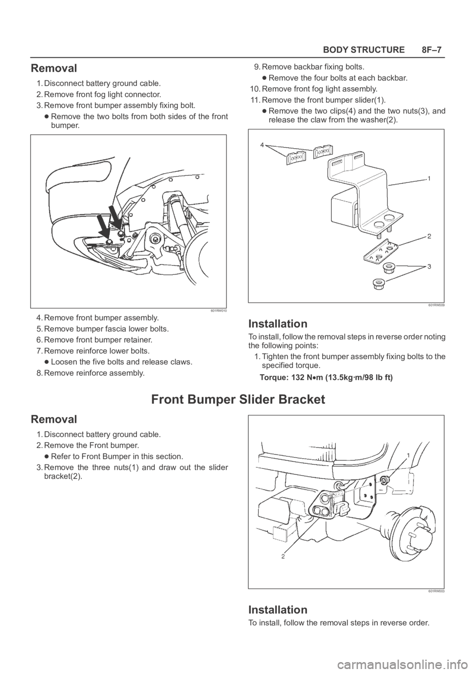
3. Remove front bumper assembly fixing bolt.
Remove the two bolts from both sides of the front
bumper.
601RW010
4. Remove front bumper assembly.
5. Remove bumper fascia lower bolts.
6. Remove front bumper retainer.
7. Remove reinforce lower bolts.
Loosen the five bolts and release claws.
8. Remove reinforce assembly.9. Remove backbar fixing bolts.
Remove the four bolts at each backbar.
10. Remove front fog light assembly.
11. Remove the front bumper slider(1).
Remove the two clips(4) and the two nuts(3), and
release the claw from the washer(2).
601RW009
Installation
To install, follow the removal steps in reverse order noting
the following points:
1. Tighten the front bumper assembly fixing bolts to the
specified torque.
To r q u e : 1 3 2 N
m (13.5kgꞏm/98 lb ft)
Front Bumper Slider Bracket
Removal
1. Disconnect battery ground cable.
2. Remove the Front bumper.
Refer to Front Bumper in this section.
3. Remove the three nuts(1) and draw out the slider
bracket(2).
601RW003
Installation
To install, follow the removal steps in reverse order.