Page 2332 of 6000

7B–14MANUAL TRANSMISSION
7. Install the engine rear mount to the transmission case
and tighten the fixing bolts specified torque (6VE1).
Torque: 41 Nꞏm (4.2kgꞏm/30 Ib ft)
8. Install the third crossmember to the frame and tighten
the fixing bolts specified torque.
Torque: 50 Nꞏm (5.1kgꞏm/37 Ib ft)
9. Tighten the engine rear mount nuts specified torque.
Torque: 50 Nꞏm (5.1kgꞏm/37 Ib ft)
10. Remove the transmission jack.
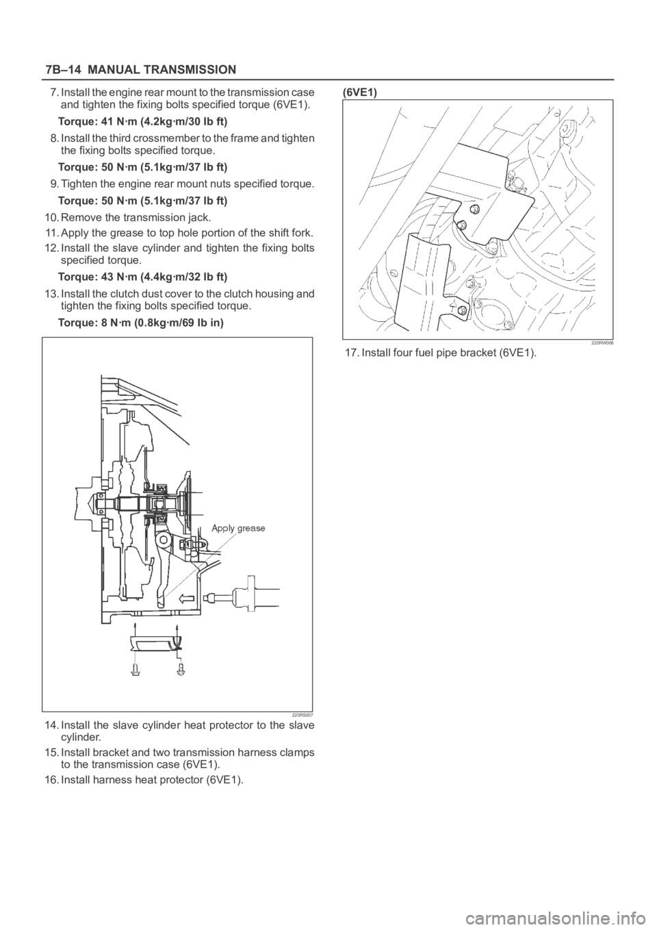
11. Apply the grease to top hole portion of the shift fork.
12. Install the slave cylinder and tighten the fixing bolts
specified torque.
Torque: 43 Nꞏm (4.4kgꞏm/32 Ib ft)
13. Install the clutch dust cover to the clutch housing and
tighten the fixing bolts specified torque.
Torque: 8 Nꞏm (0.8kgꞏm/69 Ib in)
220RS007
14. Install the slave cylinder heat protector to the slave
cylinder.
15. Install bracket and two transmission harness clamps
to the transmission case (6VE1).
16. Install harness heat protector (6VE1).(6VE1)
225RW006
17. Install four fuel pipe bracket (6VE1).
Page 2337 of 6000
MANUAL TRANSMISSION7B–19
(32) Thrust Washer Pin
(33) Reverse Idle Gear
(34) Reverse Idle Gear Shaft
(35) Counter Gear Shaft Center Bearing
(36) Snap Ring
(37) Thrust Washer
(38) Roller Bearing(39) Counter 5th Gear
(40) Reverse Block Ring
(41) Synchronizer Assembly
(42) Hub Sleeve No.3
(43) 5th Gear Spline Piece
(44) Snap Ring
226RW00001
Legend
(1) 3rd-4th Shift Arm
(2) 1st-2nd Shift Arm
(3) 3rd-4th Shift Rod
(4) Ball
(5) Spring
(6) 1st-2nd Shift Rod
(7) Snap Ring
(8) Interlock Pin(9) Reverse Shift Arm Bracket
(10) E–Ring
(11) Reverse Shift Arm No.2
(12) Reverse Shift Arm No.1
(13) 5th Reverse Shift Rod
(14) Spring Pin
(15) 5th Shift Arm
(16) Reverse Shift Rod
Page 2356 of 6000
7B–38MANUAL TRANSMISSION
14. Pull out reverse shift rod from reverse shift arm
No.1.
NOTE: Be sure remove at the rear.
226RW055
15. Using a magnetic finger, remove the ball and
spring from reverse shift arm No.1.
226RW056
16. Remove the reverse shift arm No.2 E–ring.
Remove the reverse shift arm No.2 from reverse
shift arm No.1.
226RW089
17. Remove the 2 bolts and reverse shift arm bracket.
226RW054
Page 2371 of 6000
MANUAL TRANSMISSION7B–53
2. Using 2 bolts, install reverse shift arm bracket.
Torque: 18 Nꞏm (1.8 kgꞏm/13 lb ft)
226RW054
3. Install reverse shift arm No.2 to the reverse shift
arm No.1. Using screwdriver and a hammer,
install the new E-ring.
226RW138
4. Install reverse shift arm No.2 to the reverse shift
arm bracket.
226RW012
20. Install the reverse shift rod.
1. Install the reverse shift arm No.1 compression
spring and ball to the reverse shift arm No.1.
226RW125
Page 2519 of 6000
7C–10CLUTCH
5. Mark the flywheel, clutch cover and pressure plate lug
for alignment when installing.
6. Remove the release bearing (3) from the
transmission case .
7. Remove the shift fork snap pin.
8. Remove the shift fork pin and shift fork (4) from the
front cover.
9. Remove the front cover bolts.
10. Remove the front cover (5) from the transmission
case.
220RW088
11. Remove flywheel assembly and crankshaft bearing.
Do not remove except for replacement.
12. Use the remover 5–8840–2000–0 (J–5822) and
sliding hammer 5–8840–0019–0 (J–23907) to
remove the crankshaft bearing
015RW053
Inspection and Repair
Make necessary correction or parts replacement if wear,
damage, or any other abnormal condition are found
through inspection.
Pressure Plate Assembly
201RS002
1. Visually check the pressure plate friction surface for
excessive wear and heat cracks.
2. If excessive wear or deep heat cracks are present,
the pressure plate must be replaced.
Pressure Plate Warpage
201RS003
Page 2520 of 6000

CLUTCH7C–11
1. Use a straight edge and a feeler gauge to measure
the pressure plate friction surface flatness in four
directions.
2. If any of the measured values exceeds the specified
limit, the pressure plate must be replaced.
Pressure Plate Warpage
Limit: 0.3 mm (0.012 in)
Clutch Cover
201RS004
1. Visually check the entire clutch cover for excessive
wear, cracking, and other damage.
2. The clutch cover must be replaced if any of these
conditions are present.
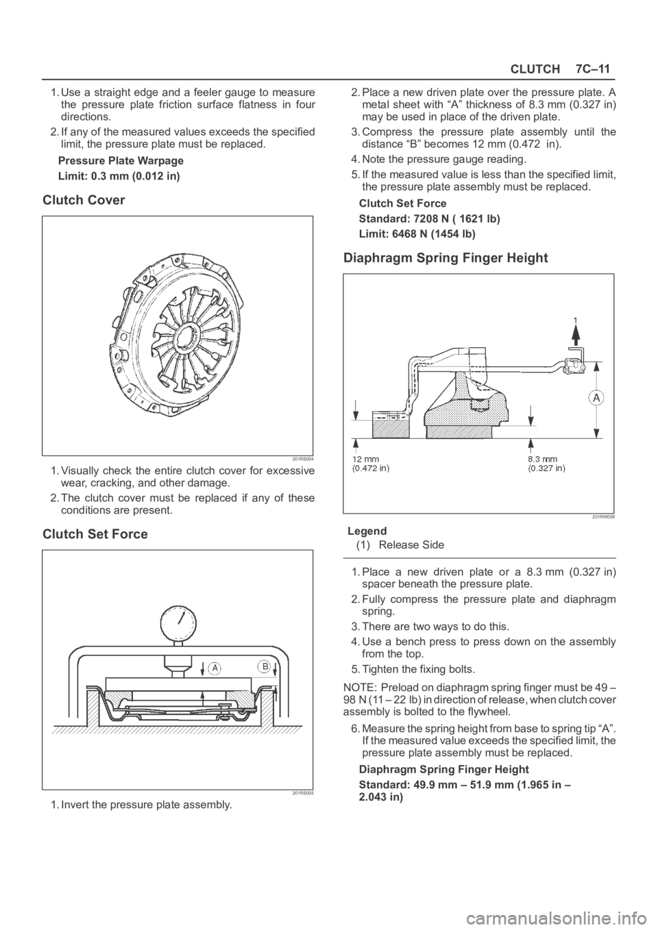
Clutch Set Force
201RS005
1. Invert the pressure plate assembly.2. Place a new driven plate over the pressure plate. A
metal sheet with “A” thickness of 8.3 mm (0.327 in)
may be used in place of the driven plate.
3. Compress the pressure plate assembly until the
distance “B” becomes 12 mm (0.472 in).
4. Note the pressure gauge reading.
5. If the measured value is less than the specified limit,
the pressure plate assembly must be replaced.
Clutch Set Force
Standard: 7208 N ( 1621 lb)
Limit: 6468 N (1454 lb)
Diaphragm Spring Finger Height
201RW009
Legend
(1) Release Side
1. Place a new driven plate or a 8.3 mm (0.327 in)
spacer beneath the pressure plate.
2. Fully compress the pressure plate and diaphragm
spring.
3. There are two ways to do this.
4. Use a bench press to press down on the assembly
from the top.
5. Tighten the fixing bolts.
NOTE: Preload on diaphragm spring finger must be 49 –
98 N (11 – 22 lb) in direction of release, when clutch cover
assembly is bolted to the flywheel.
6. Measure the spring height from base to spring tip “A”.
If the measured value exceeds the specified limit, the
pressure plate assembly must be replaced.
Diaphragm Spring Finger Height
Standard: 49.9 mm – 51.9 mm (1.965 in –
2.043 in)
Page 2521 of 6000

7C–12CLUTCH
Driven Plate Assembly
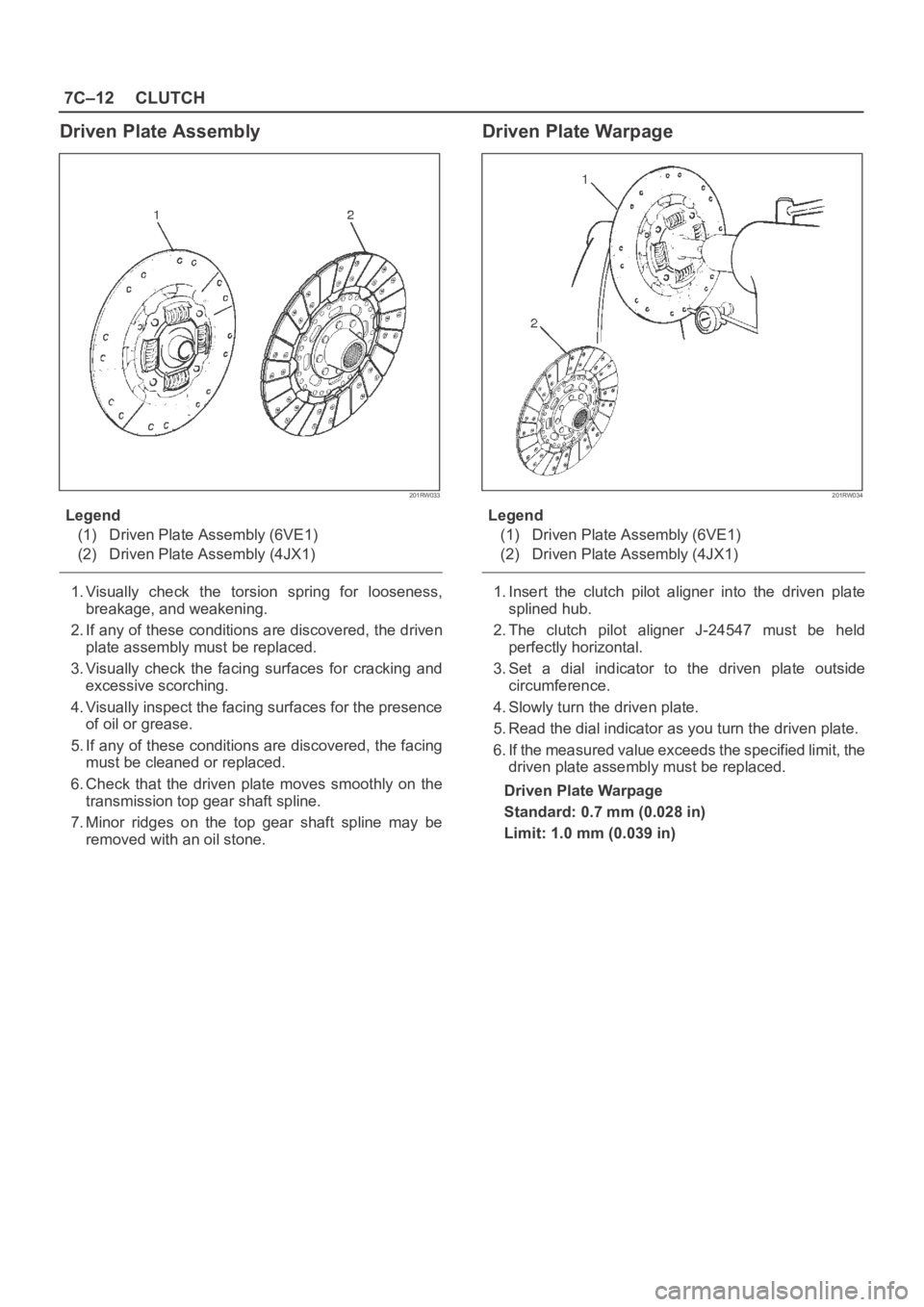
201RW033
Legend
(1) Driven Plate Assembly (6VE1)
(2) Driven Plate Assembly (4JX1)
1. Visually check the torsion spring for looseness,
breakage, and weakening.
2. If any of these conditions are discovered, the driven
plate assembly must be replaced.
3. Visually check the facing surfaces for cracking and
excessive scorching.
4. Visually inspect the facing surfaces for the presence
of oil or grease.
5. If any of these conditions are discovered, the facing
must be cleaned or replaced.
6. Check that the driven plate moves smoothly on the
transmission top gear shaft spline.
7. Minor ridges on the top gear shaft spline may be
removed with an oil stone.
Driven Plate Warpage
201RW034
Legend
(1) Driven Plate Assembly (6VE1)
(2) Driven Plate Assembly (4JX1)
1. Insert the clutch pilot aligner into the driven plate
splined hub.
2. The clutch pilot aligner J-24547 must be held
perfectly horizontal.
3. Set a dial indicator to the driven plate outside
circumference.
4. Slowly turn the driven plate.
5. Read the dial indicator as you turn the driven plate.
6. If the measured value exceeds the specified limit, the
driven plate assembly must be replaced.
Driven Plate Warpage
Standard: 0.7 mm (0.028 in)
Limit: 1.0 mm (0.039 in)
Page 2529 of 6000

7C–20CLUTCH
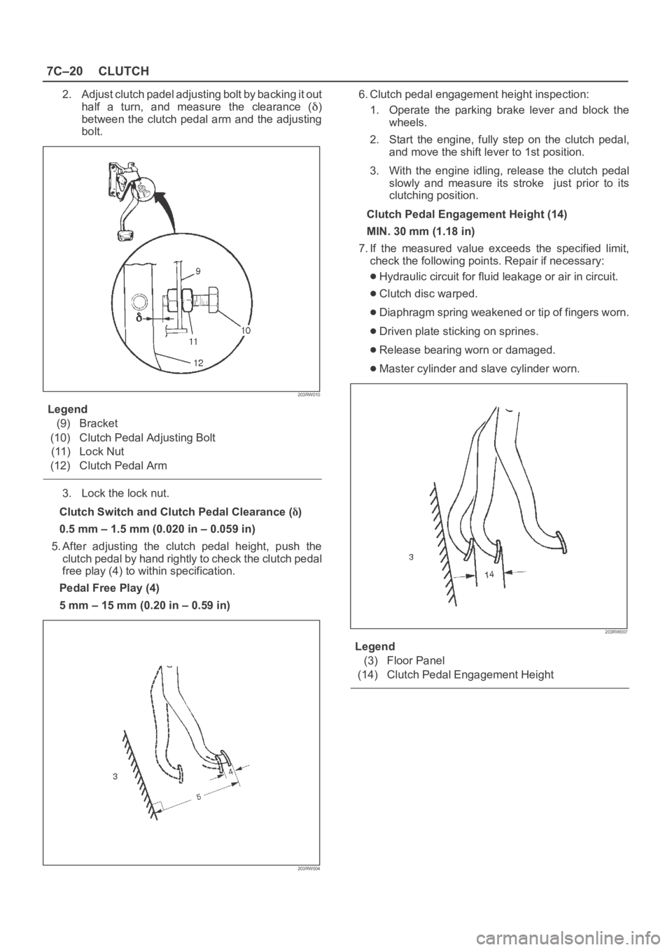
2. Adjust clutch padel adjusting bolt by backing it out
half a turn, and measure the clearance (
)
between the clutch pedal arm and the adjusting
bolt.
203RW010
Legend
(9) Bracket
(10) Clutch Pedal Adjusting Bolt
(11) Lock Nut
(12) Clutch Pedal Arm
3. Lock the lock nut.
Clutch Switch and Clutch Pedal Clearance (
)
0.5 mm – 1.5 mm (0.020 in – 0.059 in)
5. After adjusting the clutch pedal height, push the
clutch pedal by hand rightly to check the clutch pedal
free play (4) to within specification.
Pedal Free Play (4)
5 mm – 15 mm (0.20 in – 0.59 in)
203RW004
6. Clutch pedal engagement height inspection:
1. Operate the parking brake lever and block the
wheels.
2. Start the engine, fully step on the clutch pedal,
and move the shift lever to 1st position.
3. With the engine idling, release the clutch pedal
slowly and measure its stroke just prior to its
clutching position.
Clutch Pedal Engagement Height (14)
MIN. 30 mm (1.18 in)
7. If the measured value exceeds the specified limit,
check the following points. Repair if necessary:
Hydraulic circuit for fluid leakage or air in circuit.
Clutch disc warped.
Diaphragm spring weakened or tip of fingers worn.
Driven plate sticking on sprines.
Release bearing worn or damaged.
Master cylinder and slave cylinder worn.
203RW007
Legend
(3) Floor Panel
(14) Clutch Pedal Engagement Height