Page 2184 of 6000
7A–30
AUTOMATIC TRANSMISSION (4L30–E)
249RW001
Procedure 2
a. Place selector lever in neutral.
b. Disconnect transmission harness connector from
mode switch connector.
c. Remove mode switch connector with bracket from
the transmission case.
d. Connect multimeter (resistance mode) to
terminals 1(E) and 4(H) on mode switch connector.
e. Loosen two mounting screws.
f. Rotate mode switch slightly in both directions to
determine the range (approx. 5 degrees) of
electrical contact.
g. Position mode switch in middle of contact range.
h. Tighten two mounting screws.
i. Remove multimeter and install mode switch
harness connector with bracket to the
transmission case.
j. Connect transmission harness connector to mode
switch connector.
F07RW003
Page 2186 of 6000
7A–32
AUTOMATIC TRANSMISSION (4L30–E)
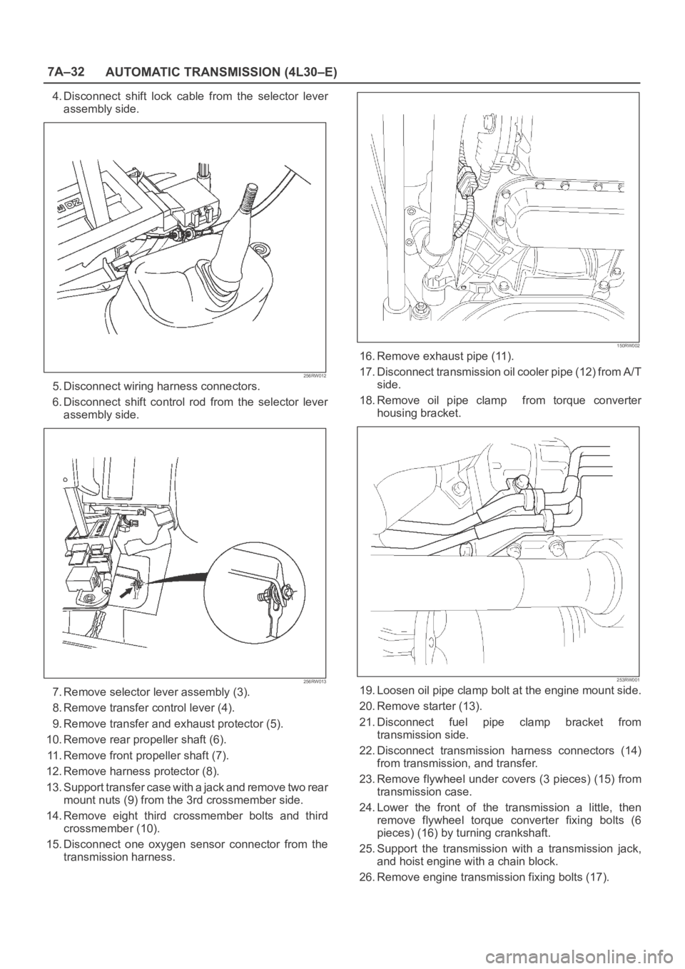
4. Disconnect shift lock cable from the selector lever
assembly side.
256RW012
5. Disconnect wiring harness connectors.
6. Disconnect shift control rod from the selector lever
assembly side.
256RW013
7. Remove selector lever assembly (3).
8. Remove transfer control lever (4).
9. Remove transfer and exhaust protector (5).
10. Remove rear propeller shaft (6).
11. Remove front propeller shaft (7).
12. Remove harness protector (8).
13. Support transfer case with a jack and remove two rear
mount nuts (9) from the 3rd crossmember side.
14. Remove eight third crossmember bolts and third
crossmember (10).
15. Disconnect one oxygen sensor connector from the
transmission harness.
150RW002
16. Remove exhaust pipe (11).
17. Disconnect transmission oil cooler pipe (12) from A/T
side.
18. Remove oil pipe clamp from torque converter
housing bracket.
253RW001
19. Loosen oil pipe clamp bolt at the engine mount side.
20. Remove starter (13).
21. Disconnect fuel pipe clamp bracket from
transmission side.
22. Disconnect transmission harness connectors (14)
from transmission, and transfer.
23. Remove flywheel under covers (3 pieces) (15) from
transmission case.
24. Lower the front of the transmission a little, then
remove flywheel torque converter fixing bolts (6
pieces) (16) by turning crankshaft.
25. Support the transmission with a transmission jack,
and hoist engine with a chain block.
26. Remove engine transmission fixing bolts (17).
Page 2188 of 6000
7A–34
AUTOMATIC TRANSMISSION (4L30–E)
5. Install the flywheel under cover (3 pieces), and tighten
the bolts to the specified torque.
Torque: 8 N
m (0.8 kgꞏm/69 lb in)
6. Install the starter, and tighten the bolts to the specified
torque.
Torque: 40 N
m (4.1 kgꞏm/30 lb ft)7. Connect transmission harness connectors to
transmission, and transfer.
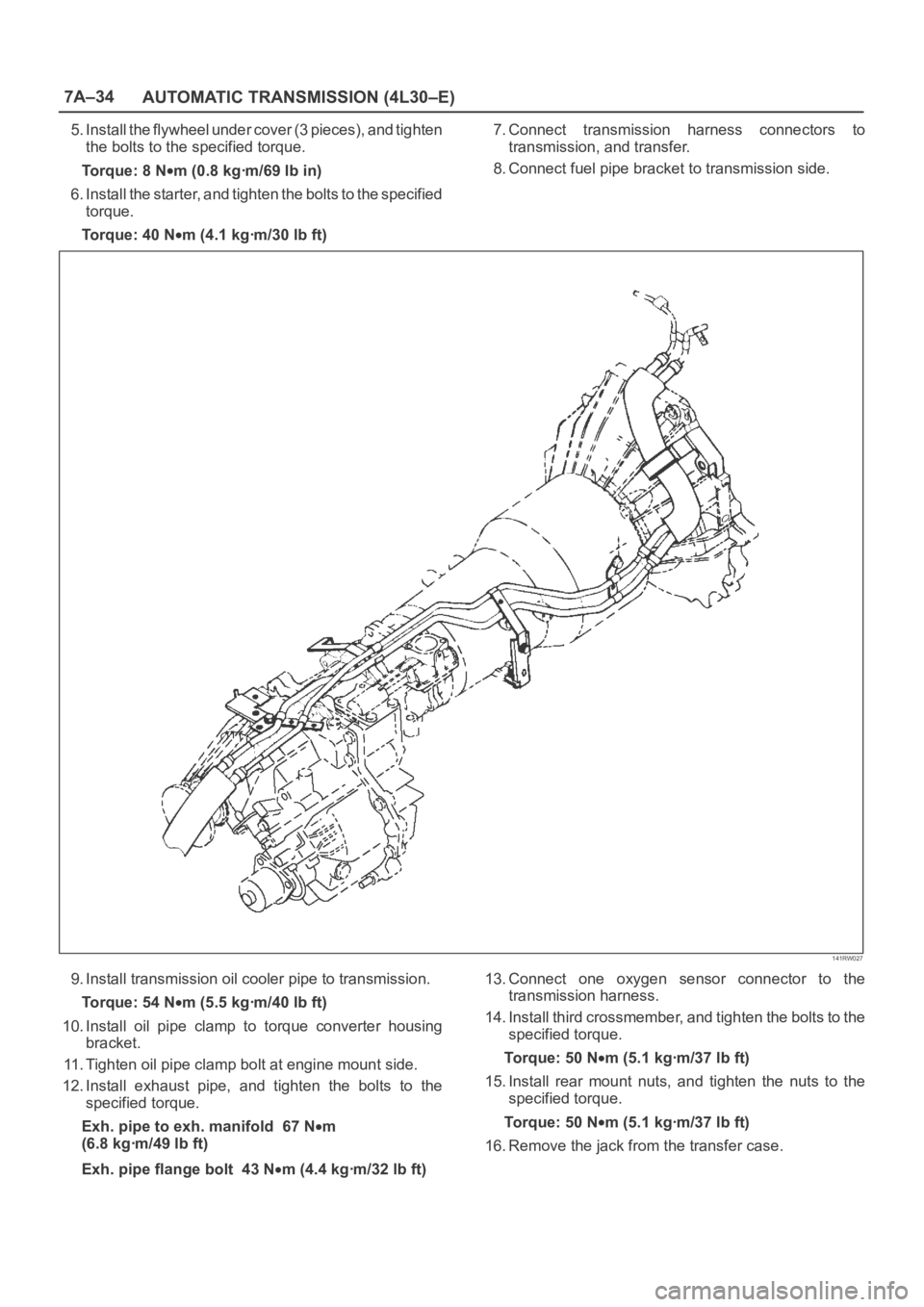
8. Connect fuel pipe bracket to transmission side.
141RW027
9. Install transmission oil cooler pipe to transmission.
Torque: 54 N
m (5.5 kgꞏm/40 lb ft)
10. Install oil pipe clamp to torque converter housing
bracket.
11. Tighten oil pipe clamp bolt at engine mount side.
12. Install exhaust pipe, and tighten the bolts to the
specified torque.
Exh. pipe to exh. manifold 67 N
m
(6.8 kgꞏm/49 lb ft)
Exh. pipe flange bolt 43 N
m (4.4 kgꞏm/32 lb ft)13. Connect one oxygen sensor connector to the
transmission harness.
14. Install third crossmember, and tighten the bolts to the
specified torque.
To r q u e : 5 0 N
m (5.1 kgꞏm/37 lb ft)
15. Install rear mount nuts, and tighten the nuts to the
specified torque.
To r q u e : 5 0 N
m (5.1 kgꞏm/37 lb ft)
16. Remove the jack from the transfer case.
Page 2194 of 6000
7A–40
AUTOMATIC TRANSMISSION (4L30–E)
Valve Body Assembly (Adapter Case)
Removal
1. Raise the vehicle and support it on jack stands.
2. Disconnect battery ground cable.
3. Drain fluid.
4. Remove transfer and exhaust protectors.
5. Remove exhaust pipe and disconnect oxygen sensor
connector.
6. Remove twelve 10 mm adapter case oil pan fixing
screws, adapter case oil pan, and gasket.
NOTE: Oil pan still contains transmission fluid. Place a
large drain container under the oil pan.
Drain the fluid carefully.
7. Disconnect wiring harness from force motor solenoid
and converter clutch solenoid. Pull only on
connectors, not on wiring harness.
8. Remove seven 13 mm screws from adapter case
valve body assembly, then remove transfer plate, two
gaskets, and adapter case valve body.
Installation
1. Inspect electrical 5 pin connector and seal of adapter
case. Replace if necessary.2. Install gasket, transfer plate, and gasket.
3. Install adapter case valve body and seven 13 mm
screws. Tighten the screws to the specified torque.
To r q u e : 2 0 N
m (2.0 kgꞏm/15 lb ft)
4. Connect wiring harness assembly to converter clutch
solenoid and force motor.
5. Install oil pan gasket, oil pan, and twelve 10 mm
screws. Tighten the screws to the specified torque.
To r q u e : 11 N
m (1.1 kgꞏm/96 lb in)
6. Install exhaust pipe and connect oxygen sensor
connector. Tighten the bolts to the specified torque.
Exhaust pipe flange bolt torque:
43 N
m(4.4kgꞏm/32lbft)
7. Install transfer and exhaust protectors. Tighten the
bolts to the specified torque.
To r q u e : 3 7 N
m(3.8kgꞏm/27lbft)
8. Fill transmission through the overfill screw hole of oil
pan, using ATF DEXRON
–III. Refer to Changing
Transmission Fluid in this section.
9. Connect battery ground cable.
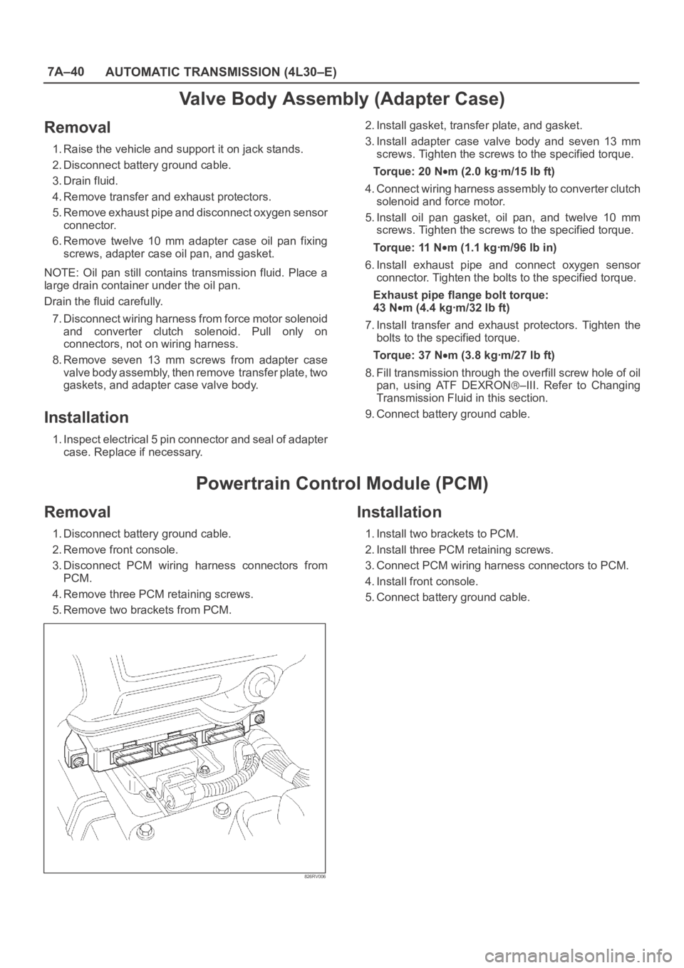
Powertrain Control Module (PCM)
Removal
1. Disconnect battery ground cable.
2. Remove front console.
3. Disconnect PCM wiring harness connectors from
PCM.
4. Remove three PCM retaining screws.
5. Remove two brackets from PCM.
826RV006
Installation
1. Install two brackets to PCM.
2. Install three PCM retaining screws.
3. Connect PCM wiring harness connectors to PCM.
4. Install front console.
5. Connect battery ground cable.
Page 2214 of 6000
7A–60
AUTOMATIC TRANSMISSION (4L30–E)
10. Remove retainer (13), 2–3 shift valve (14), and spring
(15).
11. Remove spring pin (16), plug (17), spring (18), and
low pressure control valve (19).
12. Remove spring pin (20), plug (21), and band control
screen assembly (22).
13. Remove spring pin (23), plug (24), 1–2 accumulator
valve (25), and 1–2 accumulator control valve (26).
14. Remove check ball (27) from valve body (28).
Inspection And Repair
Inspect for the following, and replace any damaged or
worn parts:
1. Damage or wear to each valve.
2. Damage in oil passeges.
3. Cracks or damage to valve body.
4. Valve operations.
5. Spring fatigue.
Reassembly
1. Install 1–2 accumulator control valve (26), 1–2
accumulator valve (25), plug (24), and spring pin (23).
2. Install band control screen assembly (22), plug (21),
and spring pin (20).
3. Install low pressure control valve (19), spring (18),
plug (17), and spring pin (16).
4. Install spring (15), 2–3 shift valve (14), retainer (13),
solenoid B (12), and spring pin (11).
5. Install spring (10), 1–2/3–4 shift valve (9), retainer (8),
solenoid A (7), and spring pin (6).
6. Install waved washer (5), band control solenoid (3),
and pin (4).
7. Install manual valve (2).
8. Install check ball (27) to valve body (28).
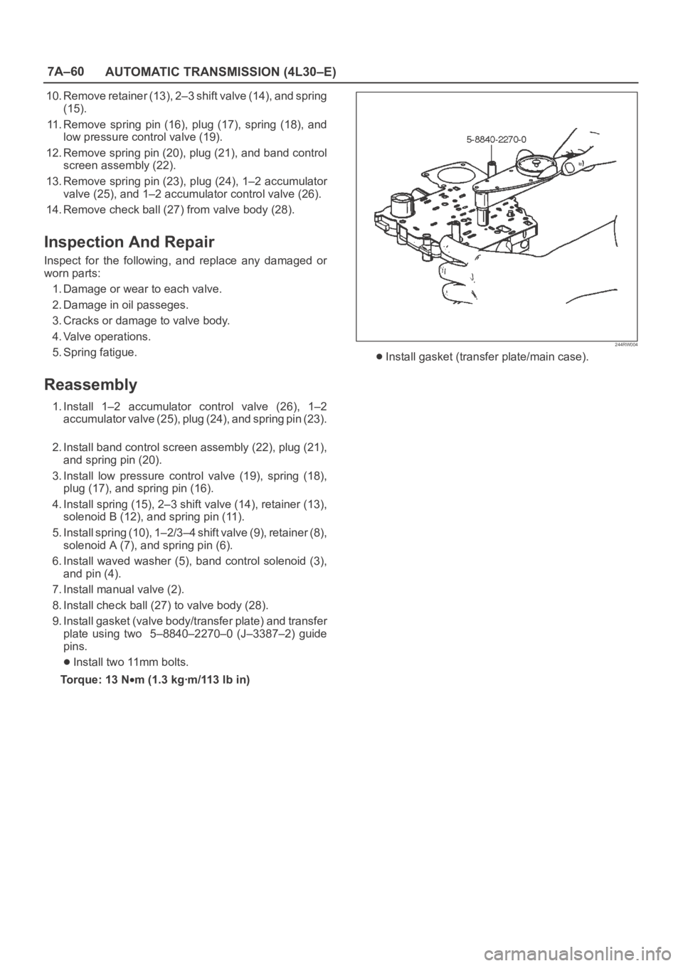
9. Install gasket (valve body/transfer plate) and transfer
plate using two 5–8840–2270–0 (J–3387–2) guide
pins.
Install two 11mm bolts.
Torque: 13 N
m (1.3 kgꞏm/113 lb in)
244RW004
Install gasket (transfer plate/main case).
Page 2215 of 6000
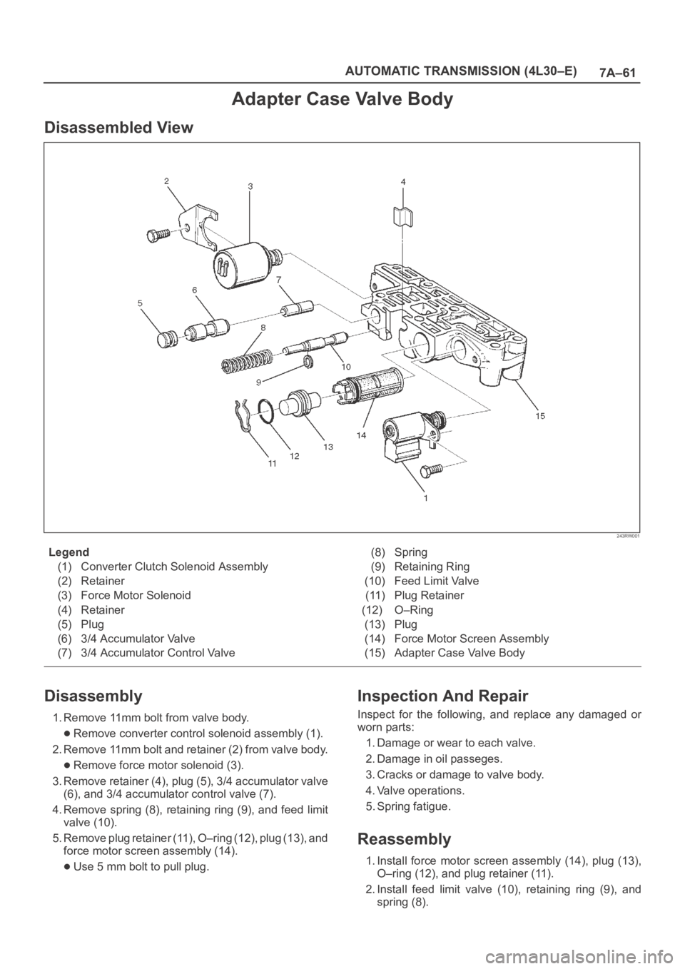
7A–61 AUTOMATIC TRANSMISSION (4L30–E)
Adapter Case Valve Body
Disassembled View
243RW001
Legend
(1) Converter Clutch Solenoid Assembly
(2) Retainer
(3) Force Motor Solenoid
(4) Retainer
(5) Plug
(6) 3/4 Accumulator Valve
(7) 3/4 Accumulator Control Valve(8) Spring
(9) Retaining Ring
(10) Feed Limit Valve
(11) Plug Retainer
(12) O–Ring
(13) Plug
(14) Force Motor Screen Assembly
(15) Adapter Case Valve Body
Disassembly
1. Remove 11mm bolt from valve body.
Remove converter control solenoid assembly (1).
2. Remove 11mm bolt and retainer (2) from valve body.
Remove force motor solenoid (3).
3. Remove retainer (4), plug (5), 3/4 accumulator valve
(6), and 3/4 accumulator control valve (7).
4. Remove spring (8), retaining ring (9), and feed limit
valve (10).
5. Remove plug retainer (11), O–ring (12), plug (13), and
force motor screen assembly (14).
Use 5 mm bolt to pull plug.
Inspection And Repair
Inspect for the following, and replace any damaged or
worn parts:
1. Damage or wear to each valve.
2. Damage in oil passeges.
3. Cracks or damage to valve body.
4. Valve operations.
5. Spring fatigue.
Reassembly
1. Install force motor screen assembly (14), plug (13),
O–ring (12), and plug retainer (11).
2. Install feed limit valve (10), retaining ring (9), and
spring (8).
Page 2326 of 6000
7B–8MANUAL TRANSMISSION
15. Remove four fuel pipe bracket from the transmission
case (6VE1).
141RW024
Page 2327 of 6000
MANUAL TRANSMISSION7B–9
16. Remove the slave cylinder heat protector.
17. Remove the harness heat protector (6VE1).
(6VE1)
225RW006
18. Remove two transmission harness clamps and
bracket (6VE1).
19. Remove the slave cylinder.
206RW002
20. Remove the two dust cover from transmission case.
21. Support the transfer case with a jack.22. Remove two engine rear mount nuts.
(6VE1)
022RT002
23. Remove third crossmember (6VE1).
24. Remove third crossmember with rear mount rubber
(4JX1).
(4JX1)
022RW013
25. Remove two engine rear mount bolts (6VE1).
26. Remove the rear mount from the transmission
(6VE1).
27. Remove three flywheel under cover (6VE1).