Page 1842 of 6000

ENGINE COOLING 6B – 9
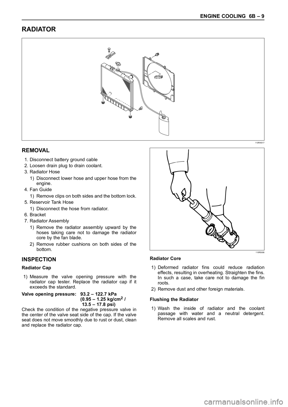
RADIATOR
REMOVAL
1. Disconnect battery ground cable
2. Loosen drain plug to drain coolant.
3. Radiator Hose
1) Disconnect lower hose and upper hose from the
engine.
4. Fan Guide
1) Remove clips on both sides and the bottom lock.
5. Reservoir Tank Hose
1) Disconnect the hose from radiator.
6. Bracket
7. Radiator Assembly
1) Remove the radiator assembly upward by the
hoses taking care not to damage the radiator
core by the fan blade.
2) Remove rubber cushions on both sides of the
bottom.
INSPECTION
Radiator Cap
1) Measure the valve opening pressure with the
radiator cap tester. Replace the radiator cap if it
exceeds the standard.
Valve opening pressure: 93.2 – 122.7 kPa
(0.95 – 1.25 kg/cm
2/
13.5 – 17.8 psi)
Check the condition of the negative pressure valve in
the center of the valve seat side of the cap. If the valve
seat does not move smoothly due to rust or dust, clean
and replace the radiator cap.Radiator Core
1) Deformed radiator fins could reduce radiation
effects, resulting in overheating. Straighten the fins.
In such a case, take care not to damage the fin
roots.
2) Remove dust and other foreign materials.
Flushing the Radiator
1) Wash the inside of radiator and the coolant
passage with water and a neutral detergent.
Remove all scales and rust.
110RW017
110RS006
Page 1843 of 6000
6B – 10 ENGINE COOLING
Checking for Coolant Leakage
1) Check the cooling system for leakage with the
radiator cap tester by applying 196.0 kPa (28.4 psi)
air pressure from filler neck to inside the radiator.
INSTALLATION
1. Radiator Assembly
1) Install rubber cushions on both sides of radiator
bottom.
2) Install radiator assembly with hose, taking care
not to damage the radiator core by a fan blade.
2. Bracket
1) Support the radiator upper tank with the bracket
and fix the radiator.
3. Reserve Tank Hose
4. Fan Guide, Lower
5. Radiator Hose
1) Connect inlet hose and outlet hose to the
engine.
2) Connect battery ground cable.
3) Pour coolant up to filler neck of radiator, and up
to MAX mark of reserve tank.
4) Start engine to warm up, and check for coolant
level. Replenish coolant if it does not reach the
radiator filler neck, and tighten the cap
completely.
110RS005
012RW080
Page 1852 of 6000
ENGINE FUEL 6C – 7
ON-VEHICLE SERVICE
FUEL FILTER ASSEMBLY
REMOVAL
1. Disconnect battery ground cable.
2. Fuel Filler cap
3. Fuel Hose
1) Disconnect fuel hose from filter body.
Plug the hose ends to prevent fuel spillage.
4. Remove the Bolt on Fuel Filter Bracket
5. Remove Fuel Filter Assembly
INSTALLATION
1. Install the fuel filter assembly
2. Tighten the Fuel Filter Bracket Fixing Bolt
3. Fuel Hose
1) Connect hoses to filter body.
4. Fuel Filler Cap
1) Connect the battery ground cable.
2) Feed fuel to the fuel pump by priming, and bleed
the air from fuel system.
FUEL FILTER CARTRIDGE
DISASSEMBLY
1. Drain fuel completely from the fuel filter.
2. Protect the filter body with cloth and lightly grip with
a vise.
3. Remove the cartridge using a filter wrench.
Filter wrench: 5-8840-0203-0
1
Legend
(1) Priming Pump
012RW111
012RW112
Page 1860 of 6000
ENGINE FUEL 6C – 15
HIGH PRESSURE OIL PUMP
REMOVAL
1. Disconnect battery ground cable.
2. Remove air cleaner cover and air duct
3. Intercooler assembly
Refer to “Intercooler” in this manual.
4. Remove high pressure oil pipe
5. Timing belt cover
Disconnect CMP sensor cable.
Remove CMP sensor bracket.
6. Tensioner
7. Timing Belt
8. Remove high pressure oil pump timing pulley
9. Remove crankshaft damper pulley
10. Remove timing gear case cover
11. Remove idle gear A
Before removing idle gear A, set two bolts to the
sub gear of idle gear A and turn it to align the teeth
of idle gear A main gear.
Then lock them by bolts as shown in the illustration.Legend
(1) Idle gear A sub gear
(2) Idle gear A main gear
(3) Bar
(4) Lock bolt
1
2
43
Legend
(1) O-Ring
(2) High Pressure Oil Pump Assembly
(3) Nut
(4) O-Ring
040RW007
4 1
2
3
014RW177
Page 1862 of 6000
ENGINE FUEL 6C – 17
INSPECTION AND REPAIR
The high pressure oil pump is made precisely,
therefore, disassembly is not recommended.
INSTALLATION
1. Set O-ring to high pressure oil pump assembly.
Install the pump assembly into the rear of timing
gear case.
Tighten nut to specified torque.
Torque: 20 Nꞏm (2.0 kgꞏm/14.5 lb ft)
Legend
(1) O-ring
(2) High Pressure Oil Pump Assembly
(3) Nuts
(4) O-ring
2. Tighten high pressure oil pump assembly bracket
together with two way valve bracket.
Torque: 27 Nꞏm (2.8 kgꞏm/20.2 lb ft)Legend
(1) High Pressure Oil Pump Assembly
(2) Nut
(3) Two Way Valve Bracket
(4) Bolt
3. Install the pump gear to align timing mark with idle
gear A.
Tighten high pressure pump gear fixing bolt to the
specified torque.
Apply engine oil to thread and seat of bolt.
Torque: 75 Nꞏm (7.6 kgꞏm/55 lb ft)
Legend
(1) O-ring
(2) Pump Gear
(3) Bolt
(4) Timing Mark
1
2
43
040RW007
2
3
4 1
040RW006
4
GEAR:O/PUMP
IDLE GEAR A
1
2
3
040RW005
Page 1863 of 6000

6C – 18 ENGINE FUEL
4. Remove lock bolt of idle gear A.
5. Install timing gear case cover.
Refer to “Timing gear” in this manual.
6. Install front plate.
Torque: 20 Nꞏm (2.0 kgꞏm/14.5 lb ft)
7. Install timing pulley of high pressure oil pump.
Torque: 10 Nꞏm (1.0 kgꞏm/7.2 lb ft)
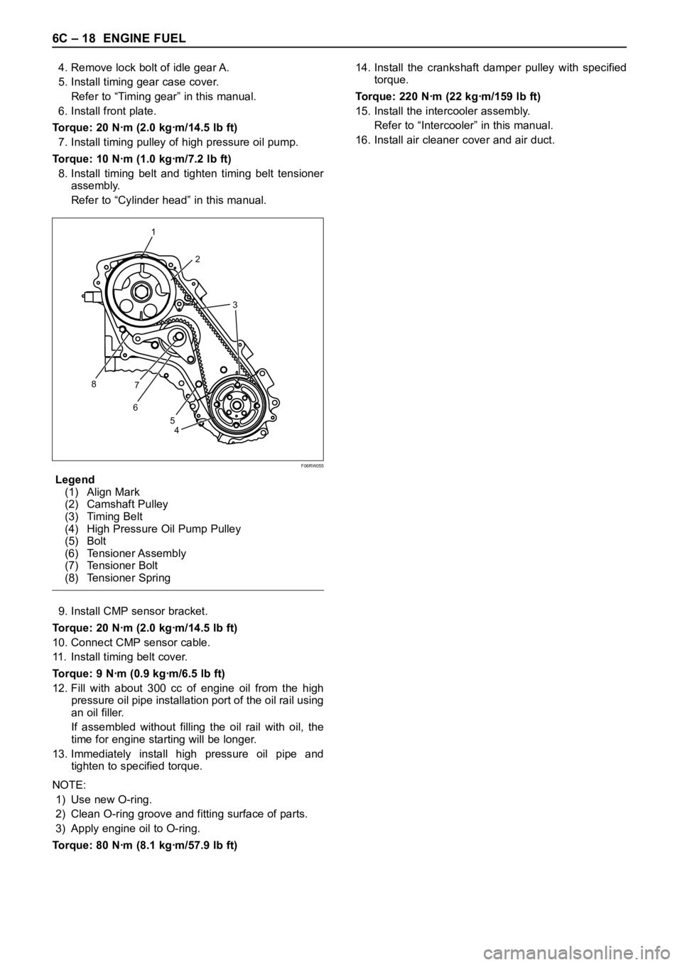
8. Install timing belt and tighten timing belt tensioner
assembly.
Refer to “Cylinder head” in this manual.
Legend
(1) Align Mark
(2) Camshaft Pulley
(3) Timing Belt
(4) High Pressure Oil Pump Pulley
(5) Bolt
(6) Tensioner Assembly
(7) Tensioner Bolt
(8) Tensioner Spring
9. Install CMP sensor bracket.
Torque: 20 Nꞏm (2.0 kgꞏm/14.5 lb ft)
10. Connect CMP sensor cable.
11. Install timing belt cover.
Torque: 9 Nꞏm (0.9 kgꞏm/6.5 lb ft)
12. Fill with about 300 cc of engine oil from the high
pressure oil pipe installation port of the oil rail using
an oil filler.
If assembled without filling the oil rail with oil, the
time for engine starting will be longer.
13. Immediately install high pressure oil pipe and
tighten to specified torque.
NOTE:
1) Use new O-ring.
2) Clean O-ring groove and fitting surface of parts.
3) Apply engine oil to O-ring.
Torque: 80 Nꞏm (8.1 kgꞏm/57.9 lb ft)14. Install the crankshaft damper pulley with specified
torque.
Torque: 220 Nꞏm (22 kgꞏm/159 lb ft)
15. Install the intercooler assembly.
Refer to “Intercooler” in this manual.
16. Install air cleaner cover and air duct.
1
2
3
8
67
4 5
F06RW055
Page 1864 of 6000

ENGINE FUEL 6C – 19
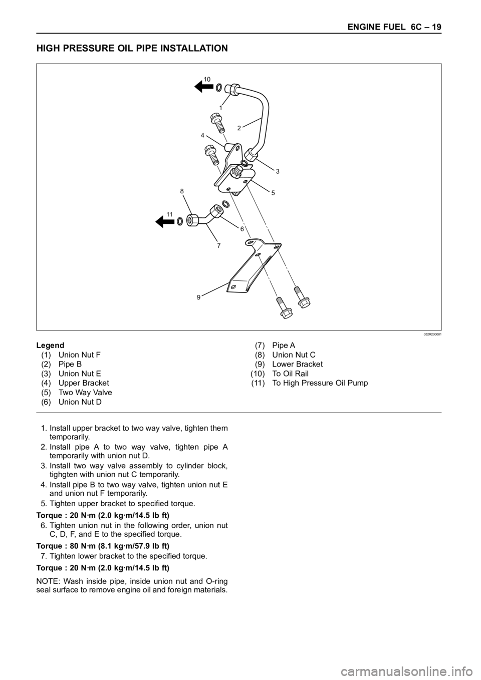
HIGH PRESSURE OIL PIPE INSTALLATION
1. Install upper bracket to two way valve, tighten them
temporarily.
2. Install pipe A to two way valve, tighten pipe A
temporarily with union nut D.
3. Install two way valve assembly to cylinder block,
tighgten with union nut C temporarily.
4. Install pipe B to two way valve, tighten union nut E
and union nut F temporarily.
5. Tighten upper bracket to specified torque.
Torque : 20 Nꞏm (2.0 kgꞏm/14.5 lb ft)
6. Tighten union nut in the following order, union nut
C, D, F, and E to the specified torque.
Torque : 80 Nꞏm (8.1 kgꞏm/57.9 lb ft)
7. Tighten lower bracket to the specified torque.
Torque : 20 Nꞏm (2.0 kgꞏm/14.5 lb ft)
NOTE: Wash inside pipe, inside union nut and O-ring
seal surface to remove engine oil and foreign materials.
6
5
7
9
8
114
1
2
3 10
Legend
(1) Union Nut F
(2) Pipe B
(3) Union Nut E
(4) Upper Bracket
(5) Two Way Valve
(6) Union Nut D(7) Pipe A
(8) Union Nut C
(9) Lower Bracket
(10) To Oil Rail
(11) To High Pressure Oil Pump
052R200001
Page 1865 of 6000

6C – 20 ENGINE FUEL
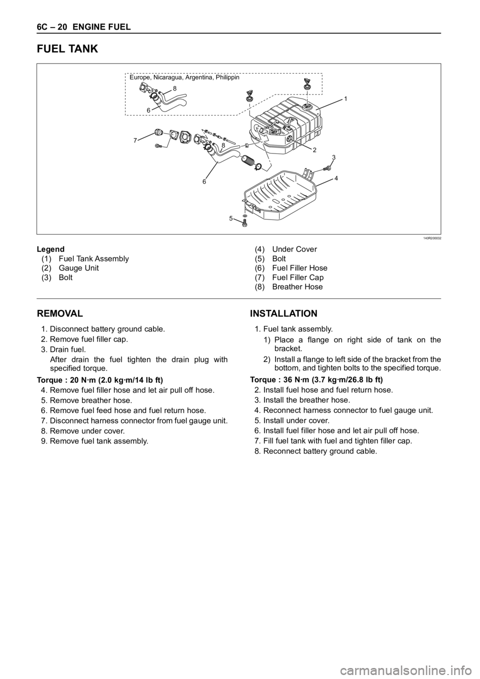
FUEL TANK
REMOVAL
1. Disconnect battery ground cable.
2. Remove fuel filler cap.
3. Drain fuel.
After drain the fuel tighten the drain plug with
specified torque.
Torque : 20 Nꞏm (2.0 kgꞏm/14 lb ft)
4. Remove fuel filler hose and let air pull off hose.
5. Remove breather hose.
6. Remove fuel feed hose and fuel return hose.
7. Disconnect harness connector from fuel gauge unit.
8. Remove under cover.
9. Remove fuel tank assembly.
INSTALLATION
1. Fuel tank assembly.
1) Place a flange on right side of tank on the
bracket.
2) Install a flange to left side of the bracket from the
bottom, and tighten bolts to the specified torque.
Torque : 36 Nꞏm (3.7 kgꞏm/26.8 lb ft)
2. Install fuel hose and fuel return hose.
3. Install the breather hose.
4. Reconnect harness connector to fuel gauge unit.
5. Install under cover.
6. Install fuel filler hose and let air pull off hose.
7. Fill fuel tank with fuel and tighten filler cap.
8. Reconnect battery ground cable.
1
2
4
8
678 Europe, Nicaragua, Argentina, Philippin
6
5
3
Legend
(1) Fuel Tank Assembly
(2) Gauge Unit
(3) Bolt(4) Under Cover
(5) Bolt
(6) Fuel Filler Hose
(7) Fuel Filler Cap
(8) Breather Hose
140R200032