Page 415 of 1659

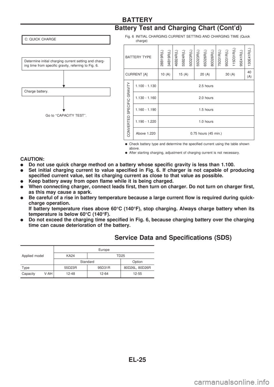
C: QUICK CHARGE
Determine initial charging current setting and charg-
ing time from specific gravity, referring to Fig. 6.
Charge battery.
Go to ``CAPACITY TEST''.Fig. 6 INITIAL CHARGING CURRENT SETTING AND CHARGING TIME (Quick
charge)
BATTERY TYPE
28B19R(L)
34B19R(L)
46B24R(L)
55B24R(L)
50D23R(L)
55D23R(L)
65D26R(L)
80D26R(L)
75D31R(L)
95D31R(L)
115D31R(L)
95E41R(L)
130E41R(L)
CURRENT [A] 10 (A) 15 (A) 20 (A) 30 (A)40
(A)
CONVERTED SPECIFIC GRAVITY
1.100 - 1.130 2.5 hours
1.130 - 1.160 2.0 hours
1.160 - 1.190 1.5 hours
1.190 - 1.220 1.0 hours
Above 1.220 0.75 hours (45 min.)
lCheck battery type and determine the specified current using the table shown
above.
lAfter starting charging, adjustment of charging current is not necessary.
CAUTION:
lDo not use quick charge method on a battery whose specific gravity is less than 1.100.
lSet initial charging current to value specified in Fig. 6. If charger is not capable of producing
specified current value, set its charging current as close to that value as possible.
lKeep battery away from open flame while it is being charged.
lWhen connecting charger, connect leads first, then turn on charger. Do not turn on charger first,
as this may cause a spark.
lBe careful of a rise in battery temperature because a large current flow is required during quick-
charge operation.
If battery temperature rises above 60ÉC (140ÉF), stop charging. Always charge battery when its
temperature is below 60ÉC (140ÉF).
lDo not exceed the charging time specified in Fig. 6, because charging battery over the charging
time can cause deterioration of the battery.
Service Data and Specifications (SDS)
Applied modelEurope
KA24 TD25
Standard Option
Type 55D23R 95D31R 80D26L, 80D26R
Capacity V-AH 12-48 12-64 12-55
.
.
BATTERY
Battery Test and Charging Chart (Cont'd)
EL-25
Page 417 of 1659

Trouble Diagnoses
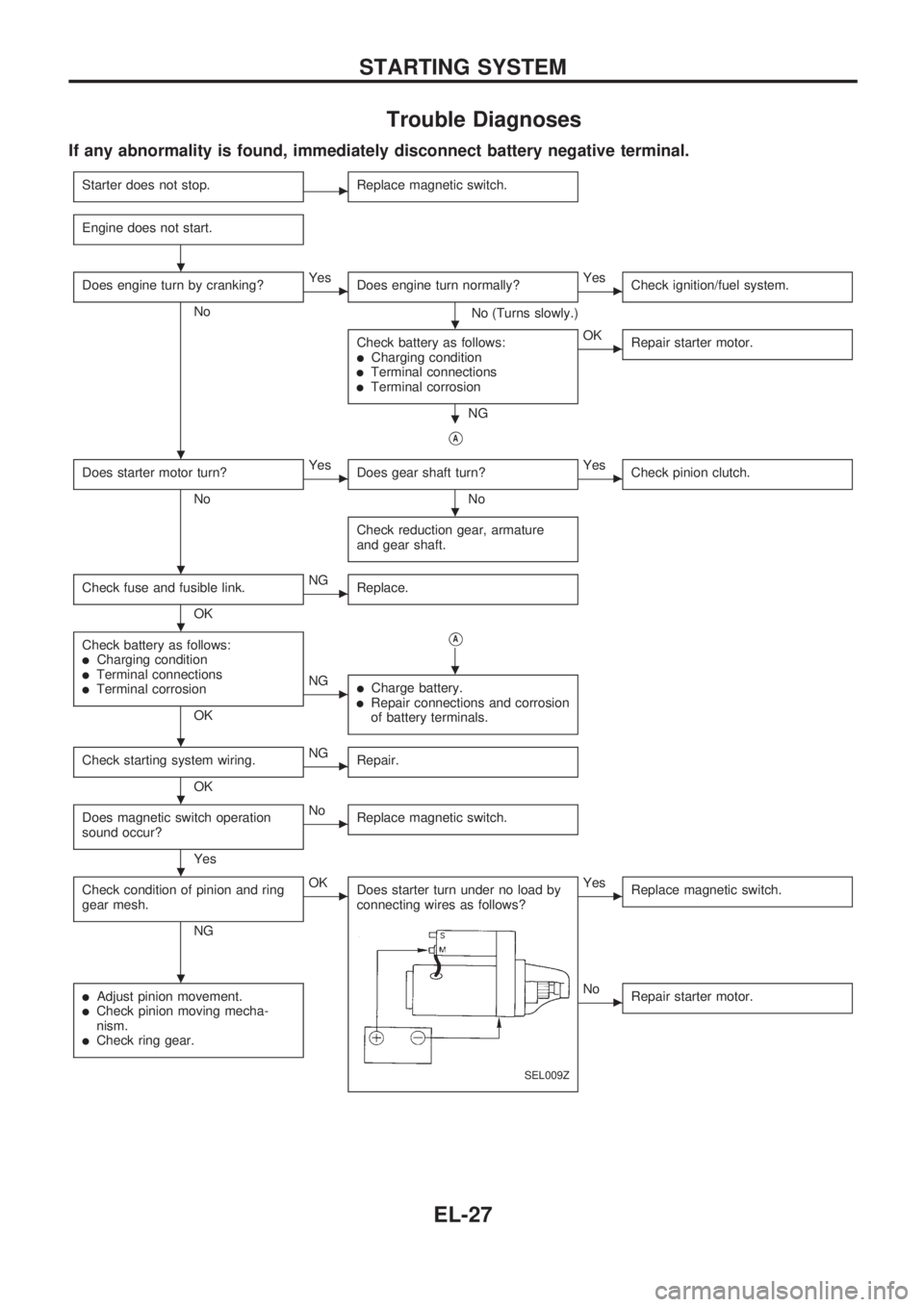
If any abnormality is found, immediately disconnect battery negative terminal.
Starter does not stop.cReplace magnetic switch.
Engine does not start.
Does engine turn by cranking?
No
cYes
Does engine turn normally?
No (Turns slowly.)
cYes
Check ignition/fuel system.
Check battery as follows:lCharging conditionlTerminal connectionslTerminal corrosion
NG
cOK
Repair starter motor.
VA
Does starter motor turn?
No
cYes
Does gear shaft turn?
No
cYes
Check pinion clutch.
Check reduction gear, armature
and gear shaft.
Check fuse and fusible link.
OK
cNG
Replace.
Check battery as follows:lCharging conditionlTerminal connectionslTerminal corrosion
OK
VA
cNGlCharge battery.lRepair connections and corrosion
of battery terminals.
Check starting system wiring.
OK
cNG
Repair.
Does magnetic switch operation
sound occur?
Yes
cNo
Replace magnetic switch.
Check condition of pinion and ring
gear mesh.
NG
cOK
Does starter turn under no load by
connecting wires as follows?
SEL009Z
cYes
Replace magnetic switch.
lAdjust pinion movement.lCheck pinion moving mecha-
nism.
lCheck ring gear.
cNo
Repair starter motor.
.
.
.
.
.
.
.
.
.
.
.
.
STARTING SYSTEM
EL-27
Page 422 of 1659
4. Check diameter of commutator.
Commutator minimum diameter:
Refer to SDS, EL-33.
lLess than specified value ... Replace.
5. Check depth of insulating mold from commutator surface.
lLess than 0.2 mm (0.008 in) ... Undercut to 0.5 to 0.8 mm
(0.020 to 0.031 in)
Assembly
Apply high-temperature grease to lubricate the bearing, gears
and frictional surface when assembling the starter.
Carefully observe the following instructions.
PINION PROTRUSION LENGTH ADJUSTMENT
Clearance ``!''
With pinion driven out by magnetic switch, push pinion back to
remove slack and measure clearance ``!'' between the front edge
of the pinion and the pinion stopper.
Clearance ``!'':
Refer to SDS, EL-33.
SEL021Z
SEL022Z
SEL026Z
STARTING SYSTEM
Inspection (Cont'd)
EL-32
Page 423 of 1659

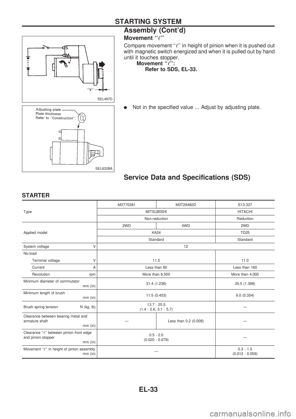
Movement ``!''
Compare movement ``!'' in height of pinion when it is pushed out
with magnetic switch energized and when it is pulled out by hand
until it touches stopper.
Movement ``!'':
Refer to SDS, EL-33.
lNot in the specified value ... Adjust by adjusting plate.
Service Data and Specifications (SDS)
STARTER
TypeM3T70381 M3T29482D S13-327
MITSUBISHI HITACHI
Non-reduction Reduction
Applied model2WD 4WD 2WD
KA24 TD25
Standard Standard
System voltage V 12
No-load
Terminal voltage V 11.5 11.0
Current A Less than 60 Less than 160
Revolution rpm More than 6,500 More than 4,000
Minimum diameter of commutator
mm (in)31.4 (1.236) 35.5 (1.398)
Minimum length of brush
mm (in)11.5 (0.453) 9.0 (0.354)
Brush spring tension N (kg, lb)13.7 - 25.5
(1.4 - 2.6, 3.1 - 5.7)Ð
Clearance between bearing metal and
armature shaft
mm (in)Ð Less than 0.2 (0.008) Ð
Clearance ``!'' between pinion front edge
and pinion stopper
mm (in)0.5 - 2.0
(0.020 - 0.079)Ð
Movement ``!'' in height of pinion assembly
mm (in)Ð0.3 - 1.5
(0.012 - 0.059)
SEL497D
SEL633BA
STARTING SYSTEM
Assembly (Cont'd)
EL-33
Page 447 of 1659
Trouble Diagnoses
DAYTIME LIGHT CONTROL UNIT INSPECTION TABLE
Terminal No. ConnectionsINPUT (I)/
OUTPUT (O)Operated conditionVoltage (V)
(Approximate
values)
1Power source for illumi-
nation & tail lampÐÐ12
2Power source for head-
lamp LHÐÐ12
3Power source for head-
lamp RHÐÐ12
4 Headlamp RH OON (daytime light operating*) 12
OFF 0
5 Headlamp LH OON (daytime light operating*) 12
OFF 0
6 Start signal I Ignition switchSTART 12
ON, ACC or OFF 0
7 Power source Ð Ignition switchON or START 12
ACC or OFF 0
8 Alternator ``L'' terminal I EngineRunning 12
Stopped 0
9 Ground Ð Ð Ð
10 Illumination & tail lamp OON (daytime light operating*) 12
OFF 0
11 Lighting switch I1STz2ND position 12
OFF 0
*: Daytime light operating: Lighting switch in ``OFF'' position with engine running.
Bulb Replacement
Refer to ``HEADLAMP'' (EL-49).
Aiming Adjustment
Refer to ``HEADLAMP'' (EL-49).
HEADLAMP Ð Daytime Light System Ð
EL-57
Page 453 of 1659
![NISSAN PICK-UP 1998 Repair Manual System Description
CIRCUIT OPERATION
[Example]
Aiming switch ``0
lWhen the aiming switch is set to ``0, the motor will not start.
This is because the power terminals are positioned at the
noncondu NISSAN PICK-UP 1998 Repair Manual System Description
CIRCUIT OPERATION
[Example]
Aiming switch ``0
lWhen the aiming switch is set to ``0, the motor will not start.
This is because the power terminals are positioned at the
noncondu](/manual-img/5/57374/w960_57374-452.png)
System Description
CIRCUIT OPERATION
[Example]
Aiming switch ``0''
lWhen the aiming switch is set to ``0'', the motor will not start.
This is because the power terminals are positioned at the
nonconductive section of the sensor's rotary unit.
Aiming switch ``0''®``1''
lWhen the aiming switch is moved from ``0'' to ``1'', the sen-
sor's conductive section activates the relay. Power is sup-
plied through the relay to the motor. The headlamps will then
move in the ``DOWN'' direction.
lThe motor continues to rotate while the rotary unit of the
sensor moves from point A to point B.
lThe power terminals will then be positioned at the noncon-
ductive section, disconnecting the power to the motor. The
motor will then stop.
Aiming switch ``1''®``0''
lWhen the aiming switch is moved from ``1'' to ``0'', the sen-
sor's conductive section activates the relay. Power is sup-
plied through the relay to the motor. The motor will rotate to
move the headlamps in the ``UP'' direction.
lWhen the rotary unit of the sensor moves from point B to
point A, the motor will stop.
SEL465M
SEL364P
SEL365P
HEADLAMP Ð Headlamp Aiming Control Ð
EL-63
Page 506 of 1659
Electrical Components Inspection
FUEL WARNING LAMP SENSOR CHECK
lIt will take a short time for the bulb to light.
OIL PRESSURE SWITCH CHECK
Oil pressure
kPa (bar, kg/cm2, psi)Continuity
Engine startMore than 10 - 20
(0.10 - 0.20, 0.1 - 0.2,1-3)NO
Engine stopLess than 10 - 20
(0.10 - 0.20, 0.1 - 0.2,1-3)YES
Check the continuity between the terminals of oil pressure switch
and body ground.
DIODE CHECK
lCheck continuity using an ohmmeter.
lDiode is functioning properly if test results are as shown in
the figure at left.
NOTE: Specification may vary depending on the type of
tester. Before performing this inspection, be sure to
refer to the instruction manual for the tester to be
used.
lDiodes for warning lamps are built into the combination meter
printed circuit.
GEL191
MEL425F
SEL901F
GEL192
WARNING LAMPS
EL-116
Page 603 of 1659

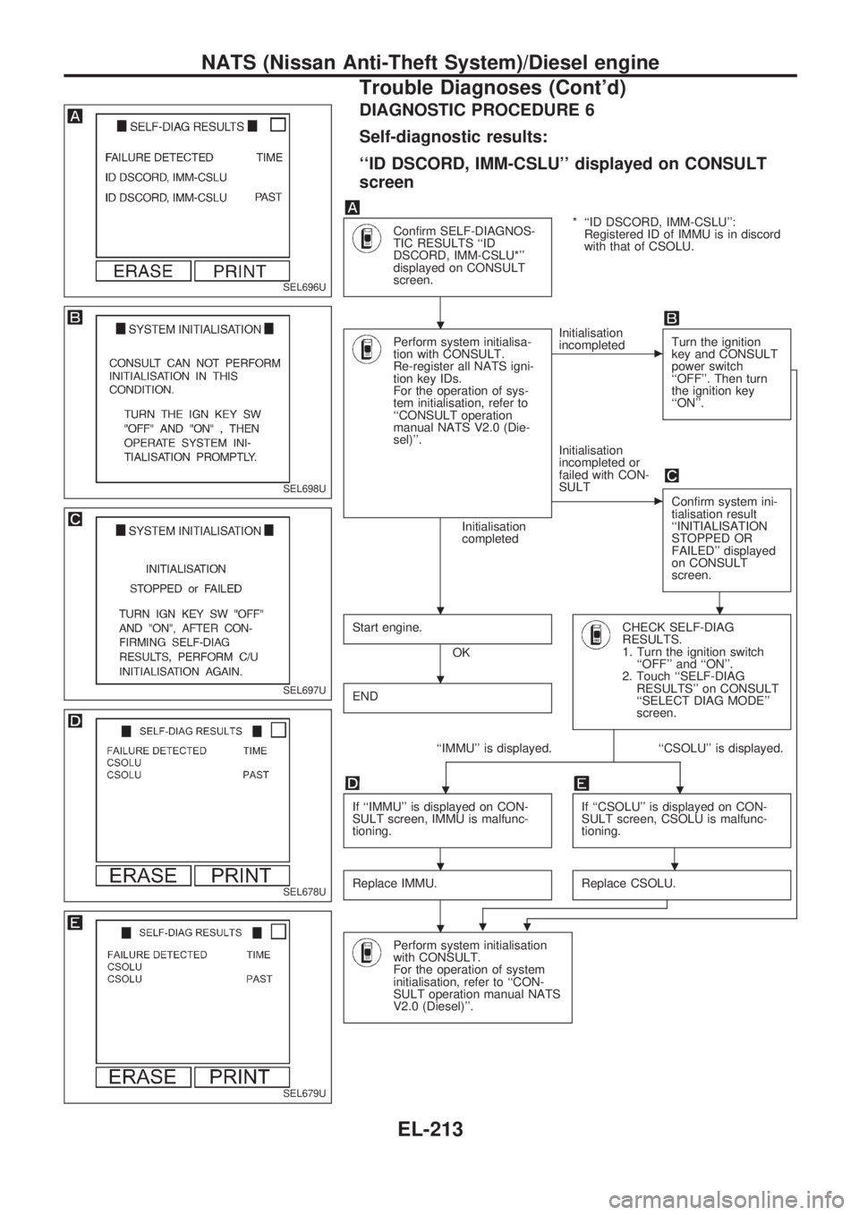
DIAGNOSTIC PROCEDURE 6
Self-diagnostic results:
``ID DSCORD, IMM-CSLU'' displayed on CONSULT
screen
Confirm SELF-DIAGNOS-
TIC RESULTS ``ID
DSCORD, IMM-CSLU*''
displayed on CONSULT
screen.* ``ID DSCORD, IMM-CSLU'':
Registered ID of IMMU is in discord
with that of CSOLU.
Perform system initialisa-
tion with CONSULT.
Re-register all NATS igni-
tion key IDs.
For the operation of sys-
tem initialisation, refer to
``CONSULT operation
manual NATS V2.0 (Die-
sel)''.
Initialisation
completedInitialisation
incompleted
cTurn the ignition
key and CONSULT
power switch
``OFF''. Then turn
the ignition key
``ON''.
Initialisation
incompleted or
failed with CON-
SULT
cConfirm system ini-
tialisation result
``INITIALISATION
STOPPED OR
FAILED'' displayed
on CONSULT
screen.
Start engine.
OK
CHECK SELF-DIAG
RESULTS.
1. Turn the ignition switch
``OFF'' and ``ON''.
2. Touch ``SELF-DIAG
RESULTS'' on CONSULT
``SELECT DIAG MODE''
screen.
END
``IMMU'' is displayed. ``CSOLU'' is displayed.
..
If ``IMMU'' is displayed on CON-
SULT screen, IMMU is malfunc-
tioning.If ``CSOLU'' is displayed on CON-
SULT screen, CSOLU is malfunc-
tioning.
Replace IMMU.Replace CSOLU.
..
Perform system initialisation
with CONSULT.
For the operation of system
initialisation, refer to ``CON-
SULT operation manual NATS
V2.0 (Diesel)''.
SEL696U
SEL698U
SEL697U
SEL678U
SEL679U
.
..
.
..
.
NATS (Nissan Anti-Theft System)/Diesel engine
Trouble Diagnoses (Cont'd)
EL-213