1998 NISSAN PICK-UP stop start
[x] Cancel search: stop startPage 643 of 1659
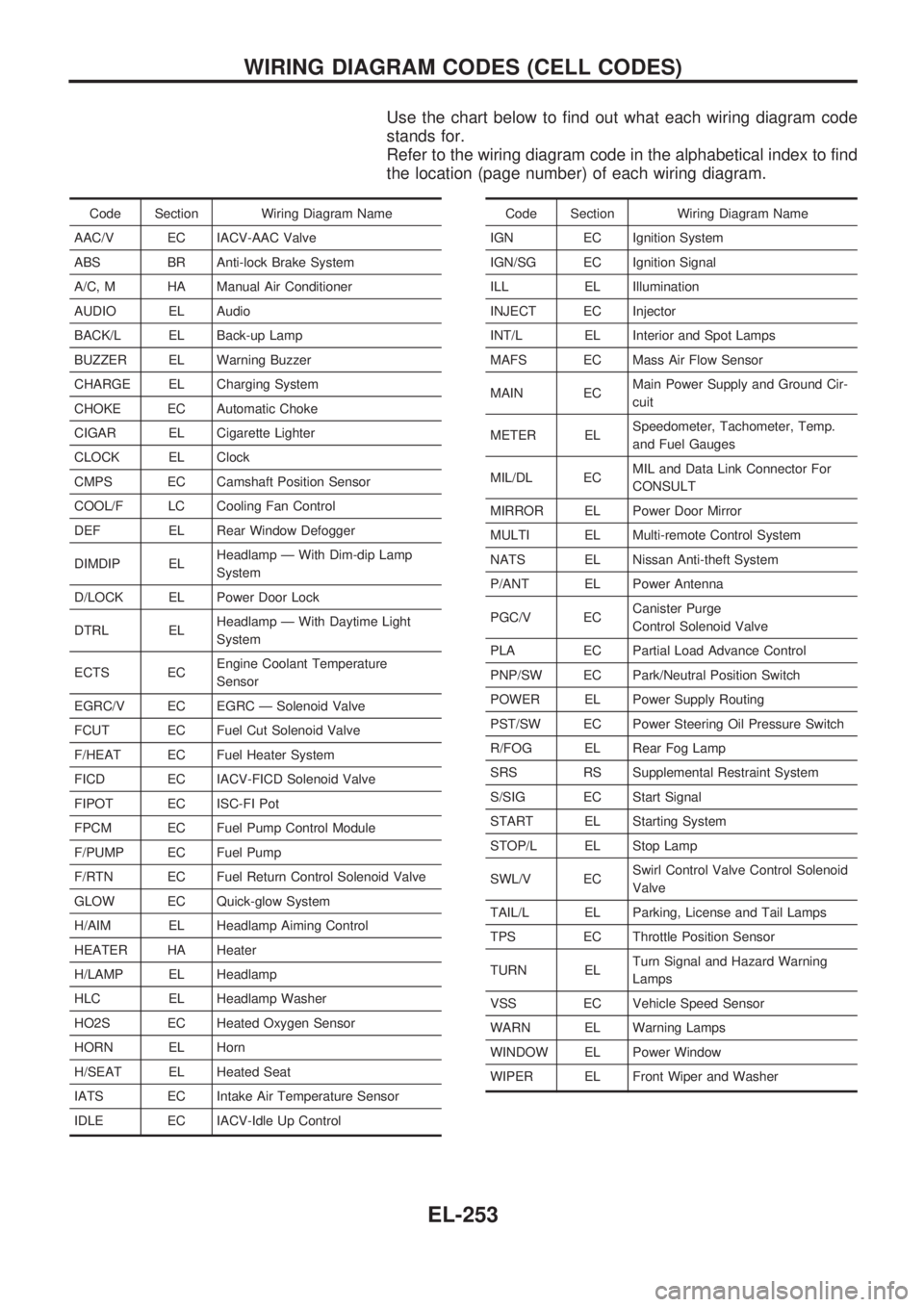
Use the chart below to find out what each wiring diagram code
stands for.
Refer to the wiring diagram code in the alphabetical index to find
the location (page number) of each wiring diagram.
Code Section Wiring Diagram Name
AAC/V EC IACV-AAC Valve
ABS BR Anti-lock Brake System
A/C, M HA Manual Air Conditioner
AUDIO EL Audio
BACK/L EL Back-up Lamp
BUZZER EL Warning Buzzer
CHARGE EL Charging System
CHOKE EC Automatic Choke
CIGAR EL Cigarette Lighter
CLOCK EL Clock
CMPS EC Camshaft Position Sensor
COOL/F LC Cooling Fan Control
DEF EL Rear Window Defogger
DIMDIP ELHeadlamp Ð With Dim-dip Lamp
System
D/LOCK EL Power Door Lock
DTRL ELHeadlamp Ð With Daytime Light
System
ECTS ECEngine Coolant Temperature
Sensor
EGRC/V EC EGRC Ð Solenoid Valve
FCUT EC Fuel Cut Solenoid Valve
F/HEAT EC Fuel Heater System
FICD EC IACV-FICD Solenoid Valve
FIPOT EC ISC-FI Pot
FPCM EC Fuel Pump Control Module
F/PUMP EC Fuel Pump
F/RTN EC Fuel Return Control Solenoid Valve
GLOW EC Quick-glow System
H/AIM EL Headlamp Aiming Control
HEATER HA Heater
H/LAMP EL Headlamp
HLC EL Headlamp Washer
HO2S EC Heated Oxygen Sensor
HORN EL Horn
H/SEAT EL Heated Seat
IATS EC Intake Air Temperature Sensor
IDLE EC IACV-Idle Up ControlCode Section Wiring Diagram Name
IGN EC Ignition System
IGN/SG EC Ignition Signal
ILL EL Illumination
INJECT EC Injector
INT/L EL Interior and Spot Lamps
MAFS EC Mass Air Flow Sensor
MAIN ECMain Power Supply and Ground Cir-
cuit
METER ELSpeedometer, Tachometer, Temp.
and Fuel Gauges
MIL/DL ECMIL and Data Link Connector For
CONSULT
MIRROR EL Power Door Mirror
MULTI EL Multi-remote Control System
NATS EL Nissan Anti-theft System
P/ANT EL Power Antenna
PGC/V ECCanister Purge
Control Solenoid Valve
PLA EC Partial Load Advance Control
PNP/SW EC Park/Neutral Position Switch
POWER EL Power Supply Routing
PST/SW EC Power Steering Oil Pressure Switch
R/FOG EL Rear Fog Lamp
SRS RS Supplemental Restraint System
S/SIG EC Start Signal
START EL Starting System
STOP/L EL Stop Lamp
SWL/V ECSwirl Control Valve Control Solenoid
Valve
TAIL/L EL Parking, License and Tail Lamps
TPS EC Throttle Position Sensor
TURN ELTurn Signal and Hazard Warning
Lamps
VSS EC Vehicle Speed Sensor
WARN EL Warning Lamps
WINDOW EL Power Window
WIPER EL Front Wiper and Washer
WIRING DIAGRAM CODES (CELL CODES)
EL-253
Page 837 of 1659

KEY TO SYMBOLS SIGNIFYING MEASUREMENTS OR PROCEDURES
Symbol Symbol explanation Symbol Symbol explanation
Check after disconnecting the connector
to be measured.Procedure with CONSULT
Check after connecting the connector to
be measured.Procedure without CONSULT
Insert key into ignition switch.A/C switch is ``OFF''.
Remove key from ignition switch.A/C switch is ``ON''.
Turn ignition switch to ``OFF'' position.Fan switch is ``ON''. (At any position
except for ``OFF'' position)
Turn ignition switch to ``ON'' position.Fan switch is ``OFF''.
Turn ignition switch to ``START'' position.Apply positive voltage from battery with
fuse directly to components.
Turn ignition switch from ``OFF'' to ``ACC''
position.Drive vehicle.
Turn ignition switch from ``ACC'' to ``OFF''
position.Disconnect battery negative cable.
Turn ignition switch from ``OFF'' to ``ON''
position.Depress brake pedal.
Turn ignition switch from ``ON'' to ``OFF''
position.Release brake pedal.
Do not start engine, or check with engine
stopped.Depress accelerator pedal.
Start engine, or check with engine run-
ning.Release accelerator pedal.
Apply parking brake.
Pin terminal check for SMJ type ECM
and TCM control unit connectors.
For details regarding the terminal
arrangement, refer to the foldout page.Release parking brake.
Check after engine is warmed up suffi-
ciently.
Voltage should be measured with a volt-
meter.
Circuit resistance should be measured
with an ohmmeter.
Current should be measured with an
ammeter.
HOW TO FOLLOW FLOW CHART IN TROUBLE DIAGNOSES
How to Follow This Flow Chart (Cont'd)
GI-33
Page 900 of 1659
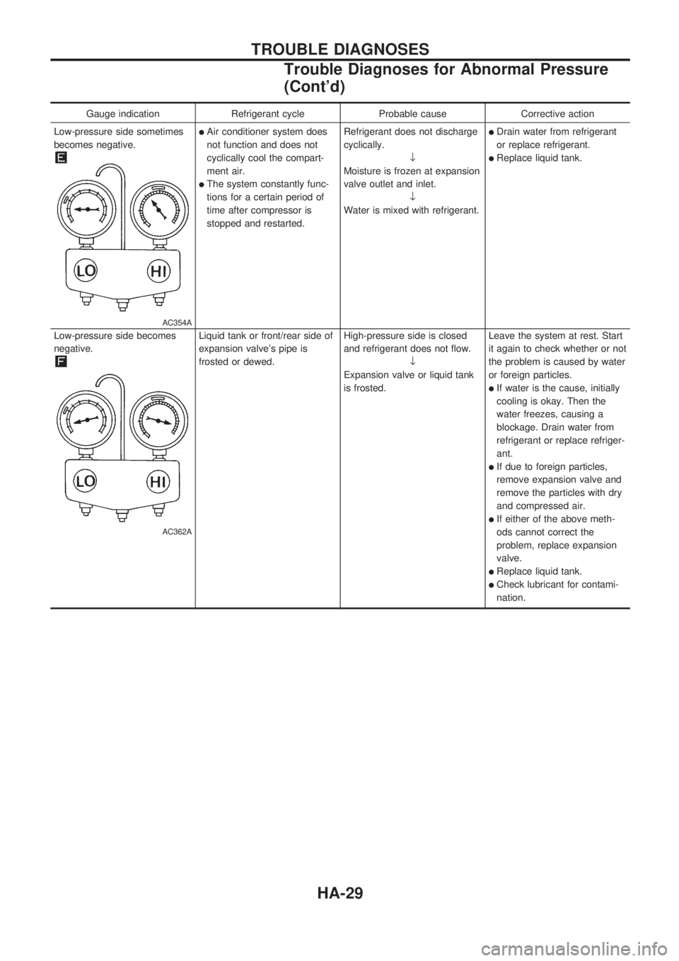
Gauge indication Refrigerant cycle Probable cause Corrective action
Low-pressure side sometimes
becomes negative.
AC354A
lAir conditioner system does
not function and does not
cyclically cool the compart-
ment air.
lThe system constantly func-
tions for a certain period of
time after compressor is
stopped and restarted.Refrigerant does not discharge
cyclically.
¯
Moisture is frozen at expansion
valve outlet and inlet.
¯
Water is mixed with refrigerant.
lDrain water from refrigerant
or replace refrigerant.
lReplace liquid tank.
Low-pressure side becomes
negative.
AC362A
Liquid tank or front/rear side of
expansion valve's pipe is
frosted or dewed.High-pressure side is closed
and refrigerant does not flow.
¯
Expansion valve or liquid tank
is frosted.Leave the system at rest. Start
it again to check whether or not
the problem is caused by water
or foreign particles.
lIf water is the cause, initially
cooling is okay. Then the
water freezes, causing a
blockage. Drain water from
refrigerant or replace refriger-
ant.
lIf due to foreign particles,
remove expansion valve and
remove the particles with dry
and compressed air.
lIf either of the above meth-
ods cannot correct the
problem, replace expansion
valve.
lReplace liquid tank.
lCheck lubricant for contami-
nation.
TROUBLE DIAGNOSES
Trouble Diagnoses for Abnormal Pressure
(Cont'd)
HA-29
Page 921 of 1659
Maintenance of Lubricant Quantity in
Compressor
The lubricant used to lubricate the compressor circulates through
the system with the refrigerant. Add lubricant to compressor
when replacing any component or after a large gas leakage
occurred. It is important to maintain the specified amount.
If lubricant quantity is not maintained properly, the following mal-
functions may result:
lLack of lubricant: May lead to a seized compressor
lExcessive lubricant: Inadequate cooling (thermal exchange
interference)
LUBRICANT
Name: Nissan A/C System Oil Type R
Part number: KLH00-PAGR0
CHECKING AND ADJUSTING
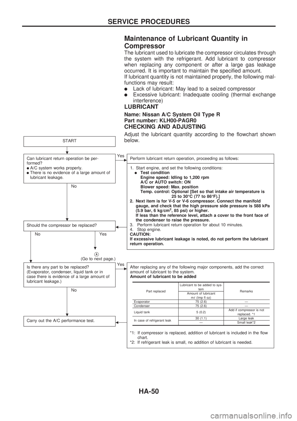
Adjust the lubricant quantity according to the flowchart shown
below.
START
Can lubricant return operation be per-
formed?
lA/C system works properly.lThere is no evidence of a large amount of
lubricant leakage.
No
cYes
Perform lubricant return operation, proceeding as follows:
-----------------------------------------------------------------------------------------------------------------------------------------------------------------------------------------------------------------------------------------------------------------------------------------------------------------------------------------------------------------------------------------------------------------------------------------------------------------------------------------------------------------------------------
1. Start engine, and set the following conditions:
lTest condition
Engine speed: Idling to 1,200 rpm
A/C or AUTO switch: ON
Blower speed: Max. position
Temp. control: Optional [Set so that intake air temperature is
25 to 30ÉC (77 to 86ÉF).]
2. Next item is for V-5 or V-6 compressor. Connect the manifold
gauge, and check that the high pressure side pressure is 588 kPa
(5.9 bar, 6 kg/cm
2, 85 psi) or higher.
If less than the reference level, attach a cover to the front face of
the condenser to raise the pressure.
3. Perform lubricant return operation for about 10 minutes.
4. Stop engine.
CAUTION:
If excessive lubricant leakage is noted, do not perform the lubricant
return operation.
Should the compressor be replaced?
No Yes
b
VA(Go to next page.)
Is there any part to be replaced?
(Evaporator, condenser, liquid tank or in
case there is evidence of a large amount of
lubricant leakage.)
No
cYes
After replacing any of the following major components, add the correct
amount of lubricant to the system.
Amount of lubricant to be added
*1: If compressor is replaced, addition of lubricant is included in the flow
chart.
*2: If refrigerant leak is small, no addition of lubricant is needed.
Carry out the A/C performance test.b
Part replacedLubricant to be added to sys-
tem
Remarks
Amount of lubricant
m!(Imp fl oz)
Evaporator 75 (2.6) Ð
Condenser 75 (2.6) Ð
Liquid tank 5 (0.2)Add if compressor is not
replaced. *1
In case of refrigerant leak30 (1.1) Large leak
Ð Small leak*2
.
.
.
.
.
SERVICE PROCEDURES
HA-50
Page 928 of 1659
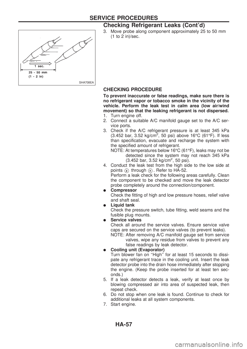
3. Move probe along component approximately 25 to 50 mm
(1 to 2 in)/sec.
CHECKING PROCEDURE
To prevent inaccurate or false readings, make sure there is
no refrigerant vapor or tobacco smoke in the vicinity of the
vehicle. Perform the leak test in calm area (low air/wind
movement) so that the leaking refrigerant is not dispersed.
1. Turn engine off.
2. Connect a suitable A/C manifold gauge set to the A/C ser-
vice ports.
3. Check if the A/C refrigerant pressure is at least 345 kPa
(3.452 bar, 3.52 kg/cm
2, 50 psi) above 16ÉC (61ÉF). If less
than specification, evacuate and recharge the system with
the specified amount of refrigerant.
NOTE: At temperatures below 16ÉC (61ÉF), leaks may not be
detected since the system may not reach 345 kPa
(3.452 bar, 3.52 kg/cm
2, 50 psi).
4. Conduct the leak test from the high side to the low side at
points
VathroughVn. Refer to HA-52.
Perform a leak check for the following areas carefully. Clean
the component to be checked and move the leak detector
probe completely around the connection/component.
lCompressor
Check the fitting of high and low pressure hoses, relief valve
and shaft seal.
lLiquid tank
Check the pressure switch, tube fitting, weld seams and the
fusible plug mounts.
lService valves
Check all around the service valves. Ensure service valve
caps are secured on the service valves (to prevent leaks).
NOTE: After removing A/C manifold gauge set from service
valves, wipe any residue from valves to prevent any
false readings by leak detector.
lCooling unit (Evaporator)
Turn blower fan on ``High'' for at least 15 seconds to dissi-
pate any refrigerant trace in the cooling unit. Insert the leak
detector probe into the drain hose immediately after stopping
the engine. (Keep the probe inserted for at least ten sec-
onds.)
5. If a leak detector detects a leak, verify at least once by
blowing compressed air into area of suspected leak, then
repeat check.
6. Do not stop when one leak is found. Continue to check for
additional leaks at all system components.
7. Start engine.
SHA708EA
SERVICE PROCEDURES
Checking Refrigerant Leaks (Cont'd)
HA-57
Page 1227 of 1659
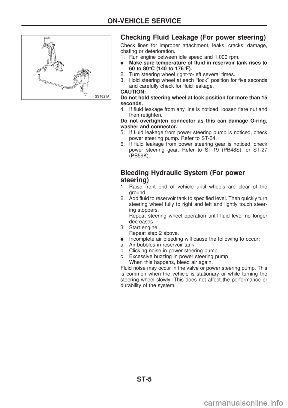
Checking Fluid Leakage (For power steering)
Check lines for improper attachment, leaks, cracks, damage,
chafing or deterioration.
1. Run engine between idle speed and 1,000 rpm.
lMake sure temperature of fluid in reservoir tank rises to
60 to 80ÉC (140 to 176ÉF).
2. Turn steering wheel right-to-left several times.
3. Hold steering wheel at each ``lock'' position for five seconds
and carefully check for fluid leakage.
CAUTION:
Do not hold steering wheel at lock position for more than 15
seconds.
4. If fluid leakage from any line is noticed, loosen flare nut and
then retighten.
Do not overtighten connector as this can damage O-ring,
washer and connector.
5. If fluid leakage from power steering pump is noticed, check
power steering pump. Refer to ST-34.
6. If fluid leakage from power steering gear is noticed, check
power steering gear. Refer to ST-19 (PB48S), or ST-27
(PB59K).
Bleeding Hydraulic System (For power
steering)
1. Raise front end of vehicle until wheels are clear of the
ground.
2. Add fluid to reservoir tank to specified level. Then quickly turn
steering wheel fully to right and left and lightly touch steer-
ing stoppers.
Repeat steering wheel operation until fluid level no longer
decreases.
3. Start engine.
Repeat step 2 above.
lIncomplete air bleeding will cause the following to occur:
a. Air bubbles in reservoir tank
b. Clicking noise in power steering pump
c. Excessive buzzing in power steering pump
When this happens, bleed air again.
Fluid noise may occur in the valve or power steering pump. This
is common when the vehicle is stationary or while turning the
steering wheel slowly. This does not affect the performance or
durability of the system.
SST621A
ON-VEHICLE SERVICE
ST-5
Page 1229 of 1659
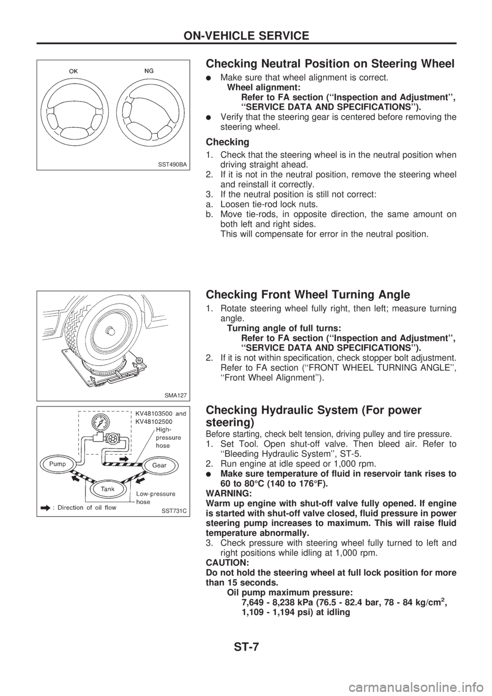
Checking Neutral Position on Steering Wheel
lMake sure that wheel alignment is correct.
Wheel alignment:
Refer to FA section (``Inspection and Adjustment'',
``SERVICE DATA AND SPECIFICATIONS'').
lVerify that the steering gear is centered before removing the
steering wheel.
Checking
1. Check that the steering wheel is in the neutral position when
driving straight ahead.
2. If it is not in the neutral position, remove the steering wheel
and reinstall it correctly.
3. If the neutral position is still not correct:
a. Loosen tie-rod lock nuts.
b. Move tie-rods, in opposite direction, the same amount on
both left and right sides.
This will compensate for error in the neutral position.
Checking Front Wheel Turning Angle
1. Rotate steering wheel fully right, then left; measure turning
angle.
Turning angle of full turns:
Refer to FA section (``Inspection and Adjustment'',
``SERVICE DATA AND SPECIFICATIONS'').
2. If it is not within specification, check stopper bolt adjustment.
Refer to FA section (``FRONT WHEEL TURNING ANGLE'',
``Front Wheel Alignment'').
Checking Hydraulic System (For power
steering)
Before starting, check belt tension, driving pulley and tire pressure.
1. Set Tool. Open shut-off valve. Then bleed air. Refer to
``Bleeding Hydraulic System'', ST-5.
2. Run engine at idle speed or 1,000 rpm.
lMake sure temperature of fluid in reservoir tank rises to
60 to 80ÉC (140 to 176ÉF).
WARNING:
Warm up engine with shut-off valve fully opened. If engine
is started with shut-off valve closed, fluid pressure in power
steering pump increases to maximum. This will raise fluid
temperature abnormally.
3. Check pressure with steering wheel fully turned to left and
right positions while idling at 1,000 rpm.
CAUTION:
Do not hold the steering wheel at full lock position for more
than 15 seconds.
Oil pump maximum pressure:
7,649 - 8,238 kPa (76.5 - 82.4 bar, 78 - 84 kg/cm
2,
1,109 - 1,194 psi) at idling
SST490BA
SMA127
SST731C
ON-VEHICLE SERVICE
ST-7
Page 1321 of 1659
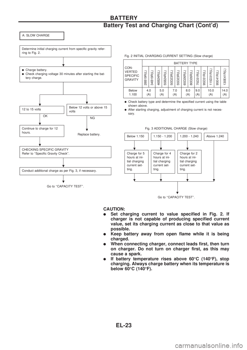
A: SLOW CHARGE
Determine initial charging current from specific gravity refer-
ring to Fig. 2.
lCharge battery.lCheck charging voltage 30 minutes after starting the bat-
tery charge.
12 to 15 volts
OKBelow 12 volts or above 15
voltsNG
Continue to charge for 12
hours.
Replace battery.
CHECKING SPECIFIC GRAVITY
Refer to ``Specific Gravity Check''.
Conduct additional charge as per Fig. 3, if necessary.
Go to ``CAPACITY TEST''.Fig. 2 INITIAL CHARGING CURRENT SETTING (Slow charge)
CON-
VERTED
SPECIFIC
GRAVITYBATTERY TYPE
28B19R(L)
34B19R(L)
46B24R(L)
55B24R(L)
50D23R(L)
55D23R(L)
65D26R(L)
80D26R(L)
75D31R(L)
95D31R(L)
115D31R(L)
95E41R(L)
130E41R(L)
Below
1.1004.0
(A)5.0
(A)7.0
(A)8.0
(A)9.0
(A)10.0
(A)14.0
(A)
lCheck battery type and determine the specified current using the table
shown above.
lAfter starting charging, adjustment of charging current is not neces-
sary.
Fig. 3 ADDITIONAL CHARGE (Slow charge)
Below 1.150
1.150 - 1.2001.200 - 1.240Above 1.240
Charge for 5
hours at ini-
tial charging
current set-
ting.Charge for 4
hours at ini-
tial charging
current set-
ting.Charge for 2
hours at ini-
tial charging
current set-
ting.
Go to ``CAPACITY TEST''.
.
CAUTION:
lSet charging current to value specified in Fig. 2. If
charger is not capable of producing specified current
value, set its charging current as close to that value as
possible.
lKeep battery away from open flame while it is being
charged.
lWhen connecting charger, connect leads first, then turn
on charger. Do not turn on charger first, as this may
cause a spark.
lIf battery temperature rises above 60ÉC (140ÉF), stop
charging. Always charge battery when its temperature is
below 60ÉC (140ÉF).
.
..
.
.
.
.
.
...
....
BATTERY
Battery Test and Charging Chart (Cont'd)
EL-23