1998 NISSAN PICK-UP stop start
[x] Cancel search: stop startPage 185 of 1659
VAVB
b
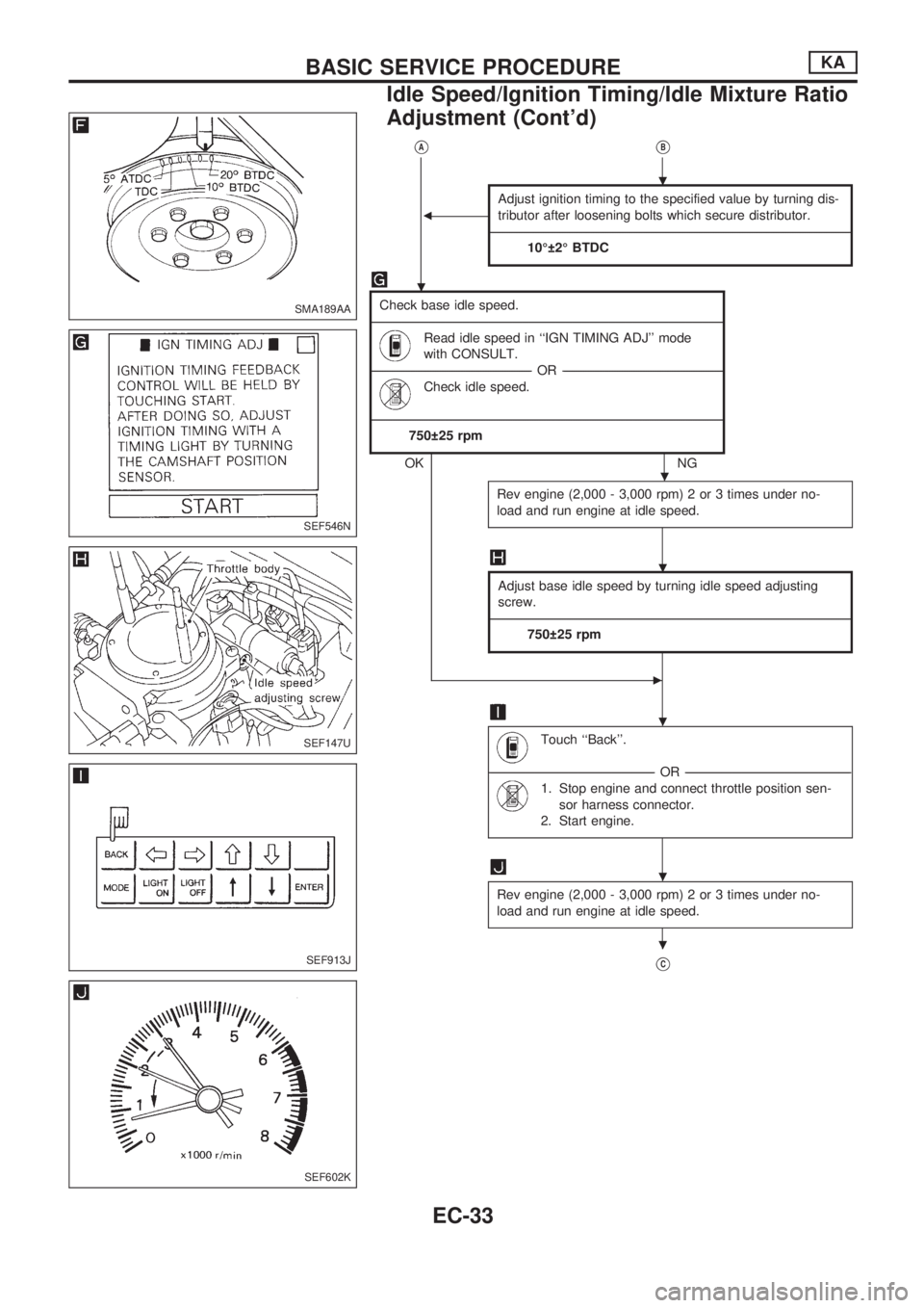
Adjust ignition timing to the specified value by turning dis-
tributor after loosening bolts which secure distributor.
------------------------------------------------------------------------------------------------------------------------------------------------------------------------------------------------------------------------------------------------------------------------------------------------------------------------------------------------------------------------------------------------------------------------
10É 2É BTDC
Check base idle speed.
--------------------------------------------------------------------------------------------------------------------------------------------------------------------------------------------------------------------------------------------------------------------------------------------------------------------------------------------------------------------------------------------------------------
Read idle speed in ``IGN TIMING ADJ'' mode
with CONSULT.
------------------------------------------------------------------------------------------------------------------------------------------------------------------------------------OR ------------------------------------------------------------------------------------------------------------------------------------------------------------------------------------
Check idle speed.
--------------------------------------------------------------------------------------------------------------------------------------------------------------------------------------------------------------------------------------------------------------------------------------------------------------------------------------------------------------------------------------------------------------
750 25 rpm
OKNG
Rev engine (2,000 - 3,000 rpm) 2 or 3 times under no-
load and run engine at idle speed.
Adjust base idle speed by turning idle speed adjusting
screw.
------------------------------------------------------------------------------------------------------------------------------------------------------------------------------------------------------------------------------------------------------------------------------------------------------------------------------------------------------------------------------------------------------------------------
750 25 rpm
c
Touch ``Back''.
------------------------------------------------------------------------------------------------------------------------------------------------------------------------------------------OR------------------------------------------------------------------------------------------------------------------------------------------------------------------------------------------
1. Stop engine and connect throttle position sen-
sor harness connector.
2. Start engine.
Rev engine (2,000 - 3,000 rpm) 2 or 3 times under no-
load and run engine at idle speed.
VC
SMA189AA
SEF546N
SEF147U
SEF913J
SEF602K
.
.
.
.
.
.
.
BASIC SERVICE PROCEDUREKA
Idle Speed/Ignition Timing/Idle Mixture Ratio
Adjustment (Cont'd)
EC-33
Page 187 of 1659
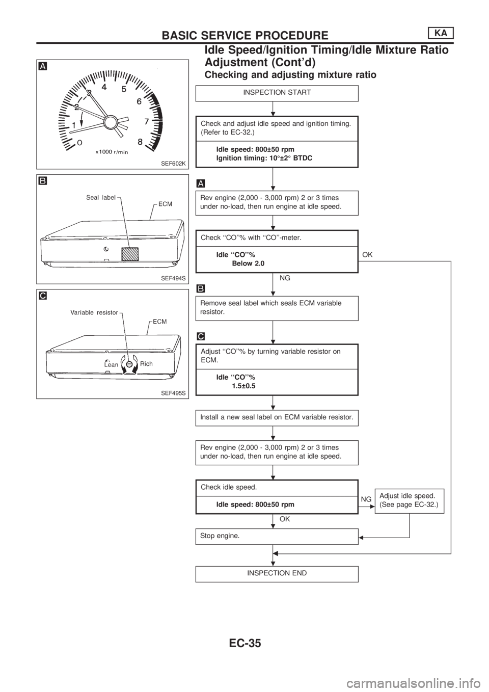
Checking and adjusting mixture ratio
INSPECTION START
Check and adjust idle speed and ignition timing.
(Refer to EC-32.)
--------------------------------------------------------------------------------------------------------------------------------------------------------------------------------------------------------------------------------------------------------------------------------------------------------------------------------------------------------
Idle speed: 800 50 rpm
Ignition timing: 10É 2É BTDC
Rev engine (2,000 - 3,000 rpm) 2 or 3 times
under no-load, then run engine at idle speed.
Check ``CO''% with ``CO''-meter.
--------------------------------------------------------------------------------------------------------------------------------------------------------------------------------------------------------------------------------------------------------------------------------------------------------------------------------------------------------
Idle ``CO''%
Below 2.0
NGOK
Remove seal label which seals ECM variable
resistor.
Adjust ``CO''% by turning variable resistor on
ECM.
--------------------------------------------------------------------------------------------------------------------------------------------------------------------------------------------------------------------------------------------------------------------------------------------------------------------------------------------------------
Idle ``CO''%
1.5 0.5
Install a new seal label on ECM variable resistor.
Rev engine (2,000 - 3,000 rpm) 2 or 3 times
under no-load, then run engine at idle speed.
Check idle speed.
--------------------------------------------------------------------------------------------------------------------------------------------------------------------------------------------------------------------------------------------------------------------------------------------------------------------------------------------------------
Idle speed: 800 50 rpm
OK
cNGAdjust idle speed.
(See page EC-32.)
Stop engine.b
b
INSPECTION END
SEF602K
SEF494S
SEF495S
.
.
.
.
.
.
.
.
.
.
BASIC SERVICE PROCEDUREKA
Idle Speed/Ignition Timing/Idle Mixture Ratio
Adjustment (Cont'd)
EC-35
Page 190 of 1659
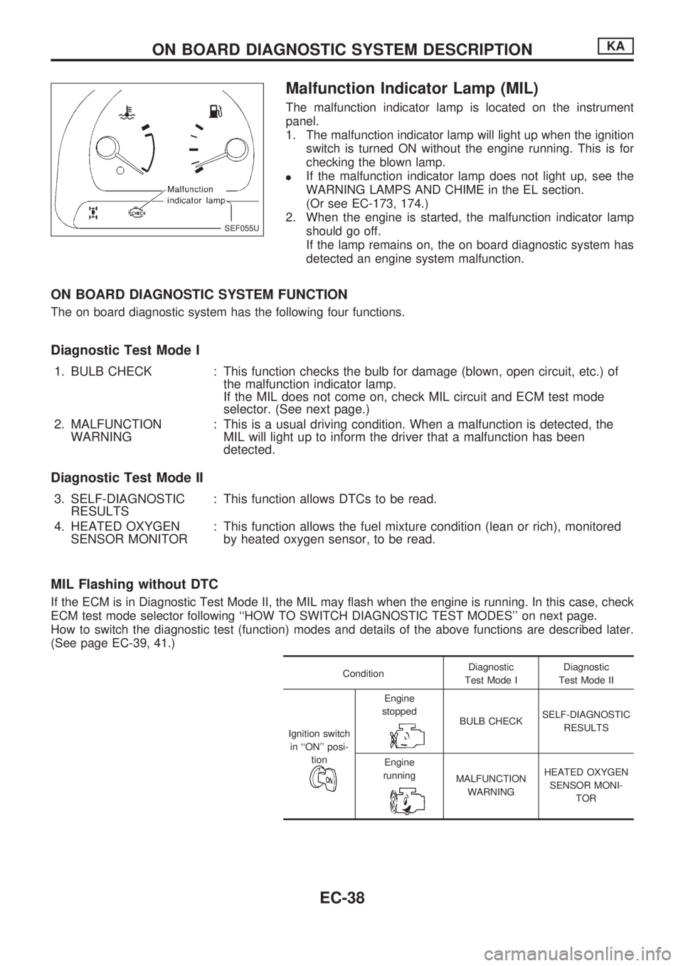
Malfunction Indicator Lamp (MIL)
The malfunction indicator lamp is located on the instrument
panel.
1. The malfunction indicator lamp will light up when the ignition
switch is turned ON without the engine running. This is for
checking the blown lamp.
lIf the malfunction indicator lamp does not light up, see the
WARNING LAMPS AND CHIME in the EL section.
(Or see EC-173, 174.)
2. When the engine is started, the malfunction indicator lamp
should go off.
If the lamp remains on, the on board diagnostic system has
detected an engine system malfunction.
ON BOARD DIAGNOSTIC SYSTEM FUNCTION
The on board diagnostic system has the following four functions.
Diagnostic Test Mode I
1. BULB CHECK : This function checks the bulb for damage (blown, open circuit, etc.) of
the malfunction indicator lamp.
If the MIL does not come on, check MIL circuit and ECM test mode
selector. (See next page.)
2. MALFUNCTION
WARNING: This is a usual driving condition. When a malfunction is detected, the
MIL will light up to inform the driver that a malfunction has been
detected.
Diagnostic Test Mode II
3. SELF-DIAGNOSTIC
RESULTS: This function allows DTCs to be read.
4. HEATED OXYGEN
SENSOR MONITOR: This function allows the fuel mixture condition (lean or rich), monitored
by heated oxygen sensor, to be read.
MIL Flashing without DTC
If the ECM is in Diagnostic Test Mode II, the MIL may flash when the engine is running. In this case, check
ECM test mode selector following ``HOW TO SWITCH DIAGNOSTIC TEST MODES'' on next page.
How to switch the diagnostic test (function) modes and details of the above functions are described later.
(See page EC-39, 41.)
ConditionDiagnostic
Test Mode IDiagnostic
Test Mode II
Ignition switch
in ``ON'' posi-
tion
Engine
stopped
BULB CHECKSELF-DIAGNOSTIC
RESULTS
Engine
running
MALFUNCTION
WARNINGHEATED OXYGEN
SENSOR MONI-
TOR
SEF055U
ON BOARD DIAGNOSTIC SYSTEM DESCRIPTIONKA
EC-38
Page 198 of 1659
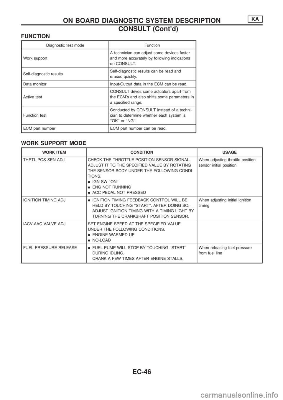
FUNCTION
Diagnostic test mode Function
Work supportA technician can adjust some devices faster
and more accurately by following indications
on CONSULT.
Self-diagnostic resultsSelf-diagnostic results can be read and
erased quickly.
Data monitor Input/Output data in the ECM can be read.
Active testCONSULT drives some actuators apart from
the ECM's and also shifts some parameters in
a specified range.
Function testConducted by CONSULT instead of a techni-
cian to determine whether each system is
``OK'' or ``NG''.
ECM part number ECM part number can be read.
WORK SUPPORT MODE
WORK ITEM CONDITION USAGE
THRTL POS SEN ADJ CHECK THE THROTTLE POSITION SENSOR SIGNAL.
ADJUST IT TO THE SPECIFIED VALUE BY ROTATING
THE SENSOR BODY UNDER THE FOLLOWING CONDI-
TIONS.
lIGN SW ``ON''
lENG NOT RUNNING
lACC PEDAL NOT PRESSEDWhen adjusting throttle position
sensor initial position
IGNITION TIMING ADJ
lIGNITION TIMING FEEDBACK CONTROL WILL BE
HELD BY TOUCHING ``START''. AFTER DOING SO,
ADJUST IGNITION TIMING WITH A TIMING LIGHT BY
TURNING THE CRANKSHAFT POSITION SENSOR.When adjusting initial ignition
timing
IACV-AAC VALVE ADJ SET ENGINE SPEED AT THE SPECIFIED VALUE
UNDER THE FOLLOWING CONDITIONS.
lENGINE WARMED UP
lNO-LOAD
FUEL PRESSURE RELEASE
lFUEL PUMP WILL STOP BY TOUCHING ``START''
DURING IDLING.
CRANK A FEW TIMES AFTER ENGINE STALLS.When releasing fuel pressure
from fuel line
ON BOARD DIAGNOSTIC SYSTEM DESCRIPTIONKA
CONSULT (Cont'd)
EC-46
Page 200 of 1659
![NISSAN PICK-UP 1998 Repair Manual SELF-DIAGNOSTIC MODE
Regarding items detected in ``SELF-DIAG RESULTS mode, refer to ``DIAGNOSTIC TROUBLE CODE
INDEX, EC-1.
DATA MONITOR MODE
Monitored item
[Unit]ECM
input
signalsMain
signalsDescr NISSAN PICK-UP 1998 Repair Manual SELF-DIAGNOSTIC MODE
Regarding items detected in ``SELF-DIAG RESULTS mode, refer to ``DIAGNOSTIC TROUBLE CODE
INDEX, EC-1.
DATA MONITOR MODE
Monitored item
[Unit]ECM
input
signalsMain
signalsDescr](/manual-img/5/57374/w960_57374-199.png)
SELF-DIAGNOSTIC MODE
Regarding items detected in ``SELF-DIAG RESULTS'' mode, refer to ``DIAGNOSTIC TROUBLE CODE
INDEX'', EC-1.
DATA MONITOR MODE
Monitored item
[Unit]ECM
input
signalsMain
signalsDescription Remarks
CMPSRPM
(POS) [rpm]
jj
lIndicates the engine speed computed
from the POS signal (1É signal) of the
camshaft position sensor.
MAS AIR/FL SE [V]
jjlThe signal voltage of the mass air flow
sensor is displayed.lWhen the engine is stopped, a certain
value is indicated.
COOLAN TEMP/S
[ÉC] or [ÉF]
jj
lThe engine coolant temperature (deter-
mined by the signal voltage of the engine
coolant temperature sensor) is displayed.lWhen the engine coolant temperature
sensor is open or short-circuited, ECM
enters fail-safe mode. The engine coolant
temperature determined by the ECM is
displayed.
O2 SEN [V]
jjlThe signal voltage of the heated oxygen
sensor is displayed.lLHD models only
M/R F/C MNT
[RICH/LEAN]
jj
lDisplay of heated oxygen sensor signal
during air-fuel ratio feedback control:
RICH ... means the mixture became
``rich'', and control is being affected
toward a leaner mixture.
LEAN ... means the mixture became
``lean'', and control is being affected
toward a rich mixture.lAfter turning ON the ignition switch,
``RICH'' is displayed until air-fuel mixture
ratio feedback control begins.
lWhen the air-fuel ratio feedback is
clamped, the value just before the clamp-
ing is displayed continuously.
lLHD models only
VHCL SPEED SE
[km/h] or [mph]
jjlThe vehicle speed computed from the
vehicle speed sensor signal is displayed.
BATTERY VOLT [V]
jjlThe power supply voltage of ECM is dis-
played.
THRTL POS SEN [V]
jjlThe throttle position sensor signal volt-
age is displayed.
INT/A TEMP SE
[ÉC] or [ÉF]
j
lThe intake air temperature (determined
by the signal voltage of the intake air
temperature sensor) is indicated.
START SIGNAL
[ON/OFF]
jjlIndicates [ON/OFF] condition from the
starter signal.lAfter starting the engine, [OFF] is
displayed regardless of the starter signal.
CLSD THL/POSI
[ON/OFF]
jj
lIndicates [ON/OFF] condition from the
throttle position sensor signal.
AIR COND SIG
[ON/OFF]
jj
lIndicates [ON/OFF] condition of the air
conditioner switch as determined by the
air conditioner signal.
P/N POSI SW
[ON/OFF]
jj
lIndicates [ON/OFF] condition from the
park/neutral position switch signal.
PW/ST SIGNAL
[ON/OFF]
jj
l[ON/OFF] condition of the power steering
oil pressure switch determined by the
power steering oil pressure signal is indi-
cated.
NOTE:
Any monitored item that does not match the vehicle being diagnosed is deleted from the display automatically.
ON BOARD DIAGNOSTIC SYSTEM DESCRIPTIONKA
CONSULT (Cont'd)
EC-48
Page 203 of 1659
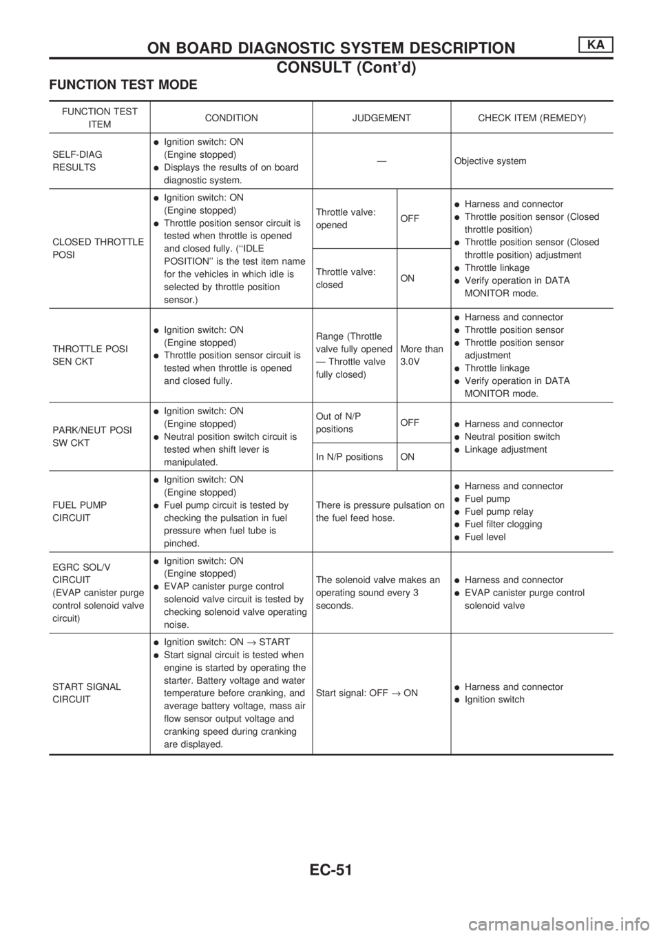
FUNCTION TEST MODE
FUNCTION TEST
ITEMCONDITION JUDGEMENT CHECK ITEM (REMEDY)
SELF-DIAG
RESULTS
lIgnition switch: ON
(Engine stopped)
lDisplays the results of on board
diagnostic system.Ð Objective system
CLOSED THROTTLE
POSI
lIgnition switch: ON
(Engine stopped)
lThrottle position sensor circuit is
tested when throttle is opened
and closed fully. (``IDLE
POSITION'' is the test item name
for the vehicles in which idle is
selected by throttle position
sensor.)Throttle valve:
openedOFF
lHarness and connector
lThrottle position sensor (Closed
throttle position)
lThrottle position sensor (Closed
throttle position) adjustment
lThrottle linkage
lVerify operation in DATA
MONITOR mode. Throttle valve:
closedON
THROTTLE POSI
SEN CKT
lIgnition switch: ON
(Engine stopped)
lThrottle position sensor circuit is
tested when throttle is opened
and closed fully.Range (Throttle
valve fully opened
Ð Throttle valve
fully closed)More than
3.0V
lHarness and connector
lThrottle position sensor
lThrottle position sensor
adjustment
lThrottle linkage
lVerify operation in DATA
MONITOR mode.
PARK/NEUT POSI
SW CKT
lIgnition switch: ON
(Engine stopped)
lNeutral position switch circuit is
tested when shift lever is
manipulated.Out of N/P
positionsOFF
lHarness and connector
lNeutral position switch
lLinkage adjustment
In N/P positions ON
FUEL PUMP
CIRCUIT
lIgnition switch: ON
(Engine stopped)
lFuel pump circuit is tested by
checking the pulsation in fuel
pressure when fuel tube is
pinched.There is pressure pulsation on
the fuel feed hose.
lHarness and connector
lFuel pump
lFuel pump relay
lFuel filter clogging
lFuel level
EGRC SOL/V
CIRCUIT
(EVAP canister purge
control solenoid valve
circuit)
lIgnition switch: ON
(Engine stopped)
lEVAP canister purge control
solenoid valve circuit is tested by
checking solenoid valve operating
noise.The solenoid valve makes an
operating sound every 3
seconds.lHarness and connector
lEVAP canister purge control
solenoid valve
START SIGNAL
CIRCUIT
lIgnition switch: ON®START
lStart signal circuit is tested when
engine is started by operating the
starter. Battery voltage and water
temperature before cranking, and
average battery voltage, mass air
flow sensor output voltage and
cranking speed during cranking
are displayed.Start signal: OFF®ON
lHarness and connector
lIgnition switch
ON BOARD DIAGNOSTIC SYSTEM DESCRIPTIONKA
CONSULT (Cont'd)
EC-51
Page 207 of 1659
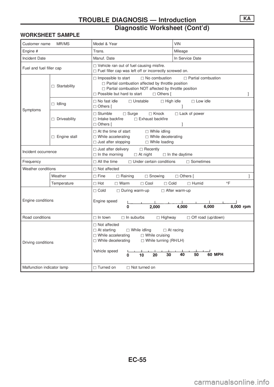
WORKSHEET SAMPLE
Customer name MR/MS Model & Year VIN
Engine # Trans. Mileage
Incident Date Manuf. Date In Service Date
Fuel and fuel filler caphVehicle ran out of fuel causing misfire.
hFuel filler cap was left off or incorrectly screwed on.
SymptomshStartabilityhImpossible to starthNo combustionhPartial combustion
hPartial combustion affected by throttle position
hPartial combustion NOT affected by throttle position
hPossible but hard to starthOthers [ ]
hIdlinghNo fast idlehUnstablehHigh idlehLow idle
hOthers [ ]
hDriveabilityhStumblehSurgehKnockhLack of power
hIntake backfirehExhaust backfire
hOthers [ ]
hEngine stallhAt the time of starthWhile idling
hWhile acceleratinghWhile decelerating
hJust after stoppinghWhile loading
Incident occurrencehJust after deliveryhRecently
hIn the morninghAt nighthIn the daytime
FrequencyhAll the timehUnder certain conditionshSometimes
Weather conditionshNot affected
WeatherhFinehRaininghSnowinghOthers [ ]
TemperaturehHothWarmhCoolhColdhHumid ÉF
Engine conditionshColdhDuring warm-uphAfter warm-up
Engine speed
Road conditionshIn townhIn suburbshHighwayhOff road (up/down)
Driving conditionshNot affected
hAt startinghWhile idlinghAt racing
hWhile acceleratinghWhile cruising
hWhile deceleratinghWhile turning (RH/LH)
Vehicle speed
Malfunction indicator lamphTurned onhNot turned on
TROUBLE DIAGNOSIS Ð IntroductionKA
Diagnostic Worksheet (Cont'd)
EC-55
Page 210 of 1659
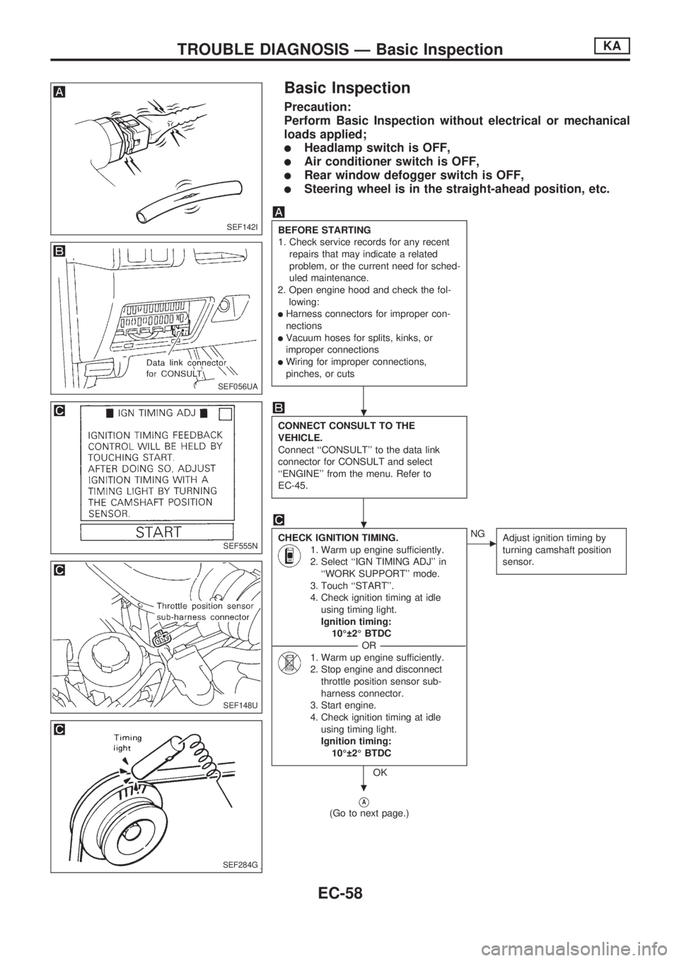
Basic Inspection
Precaution:
Perform Basic Inspection without electrical or mechanical
loads applied;
lHeadlamp switch is OFF,
lAir conditioner switch is OFF,
lRear window defogger switch is OFF,
lSteering wheel is in the straight-ahead position, etc.
BEFORE STARTING
1. Check service records for any recent
repairs that may indicate a related
problem, or the current need for sched-
uled maintenance.
2. Open engine hood and check the fol-
lowing:
lHarness connectors for improper con-
nections
lVacuum hoses for splits, kinks, or
improper connections
lWiring for improper connections,
pinches, or cuts
CONNECT CONSULT TO THE
VEHICLE.
Connect ``CONSULT'' to the data link
connector for CONSULT and select
``ENGINE'' from the menu. Refer to
EC-45.
CHECK IGNITION TIMING.
1. Warm up engine sufficiently.
2. Select ``IGN TIMING ADJ'' in
``WORK SUPPORT'' mode.
3. Touch ``START''.
4. Check ignition timing at idle
using timing light.
Ignition timing:
10É 2É BTDC
----------------------------------------------------------------------------------------------------------------------------------OR----------------------------------------------------------------------------------------------------------------------------------
1. Warm up engine sufficiently.
2. Stop engine and disconnect
throttle position sensor sub-
harness connector.
3. Start engine.
4. Check ignition timing at idle
using timing light.
Ignition timing:
10É 2É BTDC
OK
cNG
Adjust ignition timing by
turning camshaft position
sensor.
VA
(Go to next page.)
SEF142I
SEF056UA
SEF555N
SEF148U
SEF284G
.
.
.
TROUBLE DIAGNOSIS Ð Basic InspectionKA
EC-58