1998 NISSAN PICK-UP stop start
[x] Cancel search: stop startPage 303 of 1659
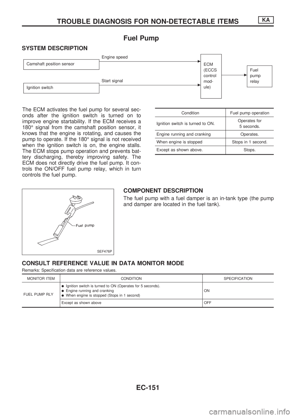
Fuel Pump
SYSTEM DESCRIPTION
Camshaft position sensorcEngine speed
ECM
(ECCS
control
mod-
ule)
cFuel
pump
relay
Ignition switchcStart signal
The ECM activates the fuel pump for several sec-
onds after the ignition switch is turned on to
improve engine startability. If the ECM receives a
180É signal from the camshaft position sensor, it
knows that the engine is rotating, and causes the
pump to operate. If the 180É signal is not received
when the ignition switch is on, the engine stalls.
The ECM stops pump operation and prevents bat-
tery discharging, thereby improving safety. The
ECM does not directly drive the fuel pump. It con-
trols the ON/OFF fuel pump relay, which in turn
controls the fuel pump.Condition Fuel pump operation
Ignition switch is turned to ON.Operates for
5 seconds.
Engine running and cranking Operates.
When engine is stopped Stops in 1 second.
Except as shown above. Stops.
COMPONENT DESCRIPTION
The fuel pump with a fuel damper is an in-tank type (the pump
and damper are located in the fuel tank).
CONSULT REFERENCE VALUE IN DATA MONITOR MODE
Remarks: Specification data are reference values.
MONITOR ITEM CONDITION SPECIFICATION
FUEL PUMP RLY
lIgnition switch is turned to ON (Operates for 5 seconds).lEngine running and crankinglWhen engine is stopped (Stops in 1 second)ON
Except as shown above OFF
SEF476P
TROUBLE DIAGNOSIS FOR NON-DETECTABLE ITEMSKA
EC-151
Page 316 of 1659
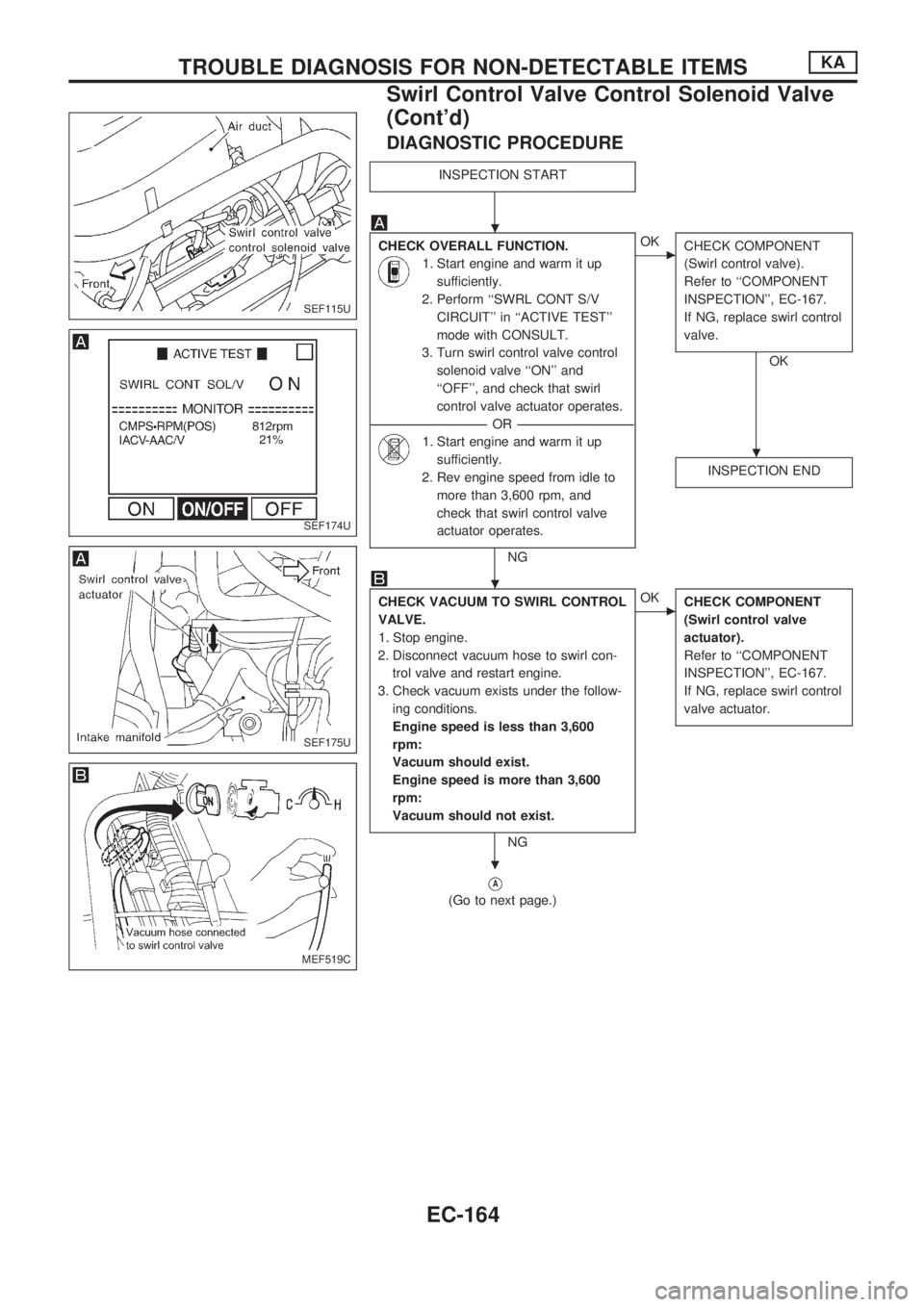
DIAGNOSTIC PROCEDURE
INSPECTION START
CHECK OVERALL FUNCTION.
1. Start engine and warm it up
sufficiently.
2. Perform ``SWRL CONT S/V
CIRCUIT'' in ``ACTIVE TEST''
mode with CONSULT.
3. Turn swirl control valve control
solenoid valve ``ON'' and
``OFF'', and check that swirl
control valve actuator operates.
----------------------------------------------------------------------------------------------------------------------------------OR----------------------------------------------------------------------------------------------------------------------------------
1. Start engine and warm it up
sufficiently.
2. Rev engine speed from idle to
more than 3,600 rpm, and
check that swirl control valve
actuator operates.
NG
cOK
CHECK COMPONENT
(Swirl control valve).
Refer to ``COMPONENT
INSPECTION'', EC-167.
If NG, replace swirl control
valve.
OK
INSPECTION END
CHECK VACUUM TO SWIRL CONTROL
VALVE.
1. Stop engine.
2. Disconnect vacuum hose to swirl con-
trol valve and restart engine.
3. Check vacuum exists under the follow-
ing conditions.
Engine speed is less than 3,600
rpm:
Vacuum should exist.
Engine speed is more than 3,600
rpm:
Vacuum should not exist.
NG
cOK
CHECK COMPONENT
(Swirl control valve
actuator).
Refer to ``COMPONENT
INSPECTION'', EC-167.
If NG, replace swirl control
valve actuator.
VA
(Go to next page.)
SEF115U
SEF174U
SEF175U
MEF519C
.
.
.
.
TROUBLE DIAGNOSIS FOR NON-DETECTABLE ITEMSKA
Swirl Control Valve Control Solenoid Valve
(Cont'd)
EC-164
Page 317 of 1659
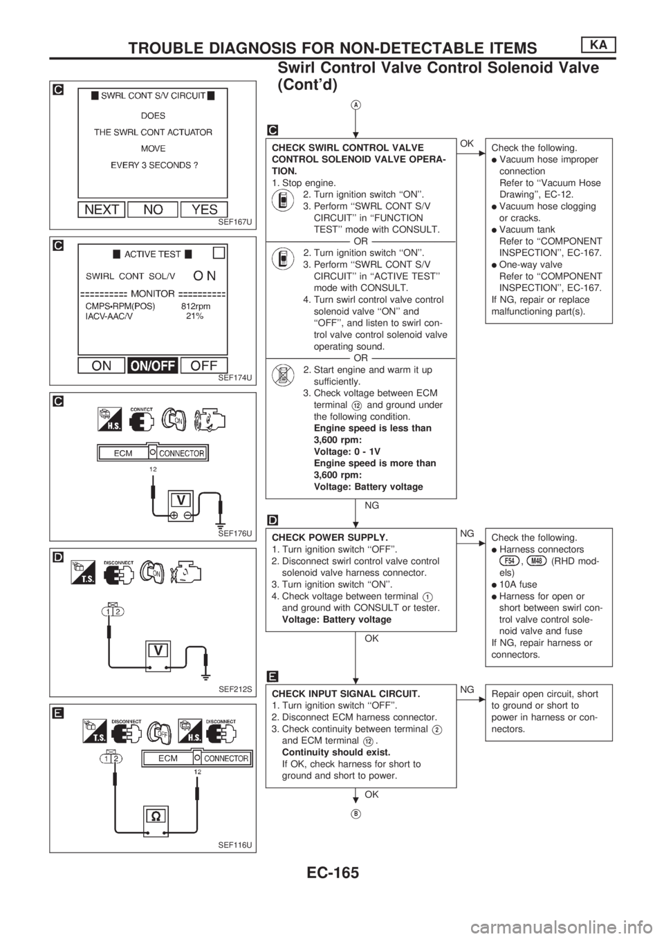
VA
CHECK SWIRL CONTROL VALVE
CONTROL SOLENOID VALVE OPERA-
TION.
1. Stop engine.
2. Turn ignition switch ``ON''.
3. Perform ``SWRL CONT S/V
CIRCUIT'' in ``FUNCTION
TEST'' mode with CONSULT.
----------------------------------------------------------------------------------------------------------------------------------OR----------------------------------------------------------------------------------------------------------------------------------
2. Turn ignition switch ``ON''.
3. Perform ``SWRL CONT S/V
CIRCUIT'' in ``ACTIVE TEST''
mode with CONSULT.
4. Turn swirl control valve control
solenoid valve ``ON'' and
``OFF'', and listen to swirl con-
trol valve control solenoid valve
operating sound.
----------------------------------------------------------------------------------------------------------------------------------OR----------------------------------------------------------------------------------------------------------------------------------
2. Start engine and warm it up
sufficiently.
3. Check voltage between ECM
terminal
V12and ground under
the following condition.
Engine speed is less than
3,600 rpm:
Voltage:0-1V
Engine speed is more than
3,600 rpm:
Voltage: Battery voltage
NG
cOK
Check the following.
lVacuum hose improper
connection
Refer to ``Vacuum Hose
Drawing'', EC-12.
lVacuum hose clogging
or cracks.
lVacuum tank
Refer to ``COMPONENT
INSPECTION'', EC-167.
lOne-way valve
Refer to ``COMPONENT
INSPECTION'', EC-167.
If NG, repair or replace
malfunctioning part(s).
CHECK POWER SUPPLY.
1. Turn ignition switch ``OFF''.
2. Disconnect swirl control valve control
solenoid valve harness connector.
3. Turn ignition switch ``ON''.
4. Check voltage between terminal
V1
and ground with CONSULT or tester.
Voltage: Battery voltage
OK
cNG
Check the following.
lHarness connectorsF54,M48(RHD mod-
els)
l10A fuse
lHarness for open or
short between swirl con-
trol valve control sole-
noid valve and fuse
If NG, repair harness or
connectors.
CHECK INPUT SIGNAL CIRCUIT.
1. Turn ignition switch ``OFF''.
2. Disconnect ECM harness connector.
3. Check continuity between terminal
V2
and ECM terminalV12.
Continuity should exist.
If OK, check harness for short to
ground and short to power.
OK
cNG
Repair open circuit, short
to ground or short to
power in harness or con-
nectors.
VB
SEF167U
SEF174U
SEF176U
SEF212S
SEF116U
.
.
.
.
TROUBLE DIAGNOSIS FOR NON-DETECTABLE ITEMSKA
Swirl Control Valve Control Solenoid Valve
(Cont'd)
EC-165
Page 323 of 1659
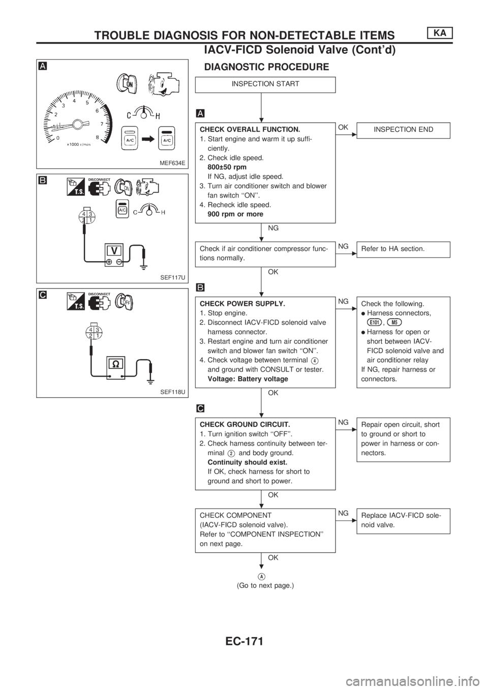
DIAGNOSTIC PROCEDURE
INSPECTION START
CHECK OVERALL FUNCTION.
1. Start engine and warm it up suffi-
ciently.
2. Check idle speed.
800 50 rpm
If NG, adjust idle speed.
3. Turn air conditioner switch and blower
fan switch ``ON''.
4. Recheck idle speed.
900 rpm or more
NG
cOK
INSPECTION END
Check if air conditioner compressor func-
tions normally.
OK
cNG
Refer to HA section.
CHECK POWER SUPPLY.
1. Stop engine.
2. Disconnect IACV-FICD solenoid valve
harness connector.
3. Restart engine and turn air conditioner
switch and blower fan switch ``ON''.
4. Check voltage between terminal
V4
and ground with CONSULT or tester.
Voltage: Battery voltage
OK
cNG
Check the following.
lHarness connectors,
E101,M5
lHarness for open or
short between IACV-
FICD solenoid valve and
air conditioner relay
If NG, repair harness or
connectors.
CHECK GROUND CIRCUIT.
1. Turn ignition switch ``OFF''.
2. Check harness continuity between ter-
minal
V2and body ground.
Continuity should exist.
If OK, check harness for short to
ground and short to power.
OK
cNG
Repair open circuit, short
to ground or short to
power in harness or con-
nectors.
CHECK COMPONENT
(IACV-FICD solenoid valve).
Refer to ``COMPONENT INSPECTION''
on next page.
OK
cNG
Replace IACV-FICD sole-
noid valve.
VA
(Go to next page.)
MEF634E
SEF117U
SEF118U
.
.
.
.
.
.
TROUBLE DIAGNOSIS FOR NON-DETECTABLE ITEMSKA
IACV-FICD Solenoid Valve (Cont'd)
EC-171
Page 372 of 1659
Description
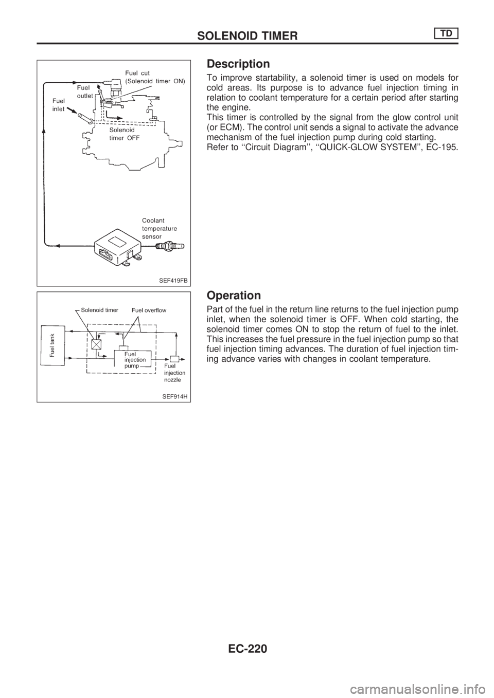
To improve startability, a solenoid timer is used on models for
cold areas. Its purpose is to advance fuel injection timing in
relation to coolant temperature for a certain period after starting
the engine.
This timer is controlled by the signal from the glow control unit
(or ECM). The control unit sends a signal to activate the advance
mechanism of the fuel injection pump during cold starting.
Refer to ``Circuit Diagram'', ``QUICK-GLOW SYSTEM'', EC-195.
Operation
Part of the fuel in the return line returns to the fuel injection pump
inlet, when the solenoid timer is OFF. When cold starting, the
solenoid timer comes ON to stop the return of fuel to the inlet.
This increases the fuel pressure in the fuel injection pump so that
fuel injection timing advances. The duration of fuel injection tim-
ing advance varies with changes in coolant temperature.
SEF419FB
SEF914H
SOLENOID TIMERTD
EC-220
Page 373 of 1659
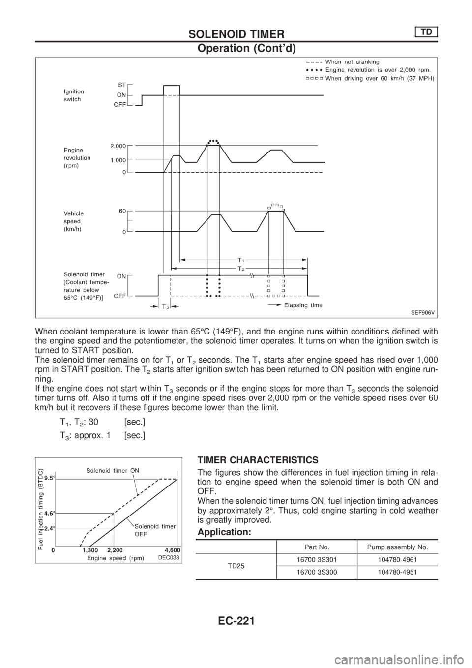
When coolant temperature is lower than 65ÉC (149ÉF), and the engine runs within conditions defined with
the engine speed and the potentiometer, the solenoid timer operates. It turns on when the ignition switch is
turned to START position.
The solenoid timer remains on for T
1or T2seconds. The T1starts after engine speed has rised over 1,000
rpm in START position. The T
2starts after ignition switch has been returned to ON position with engine run-
ning.
If the engine does not start within T
3seconds or if the engine stops for more than T3seconds the solenoid
timer turns off. Also it turns off if the engine speed rises over 2,000 rpm or the vehicle speed rises over 60
km/h but it recovers if these figures become lower than the limit.
T1,T2: 30 [sec.]
T
3: approx. 1 [sec.]
TIMER CHARACTERISTICS
The figures show the differences in fuel injection timing in rela-
tion to engine speed when the solenoid timer is both ON and
OFF.
When the solenoid timer turns ON, fuel injection timing advances
by approximately 2É. Thus, cold engine starting in cold weather
is greatly improved.
Application:
Part No. Pump assembly No.
TD2516700 3S301 104780-4961
16700 3S300 104780-4951
SEF906V
DEC033
.
SOLENOID TIMERTD
Operation (Cont'd)
EC-221
Page 413 of 1659
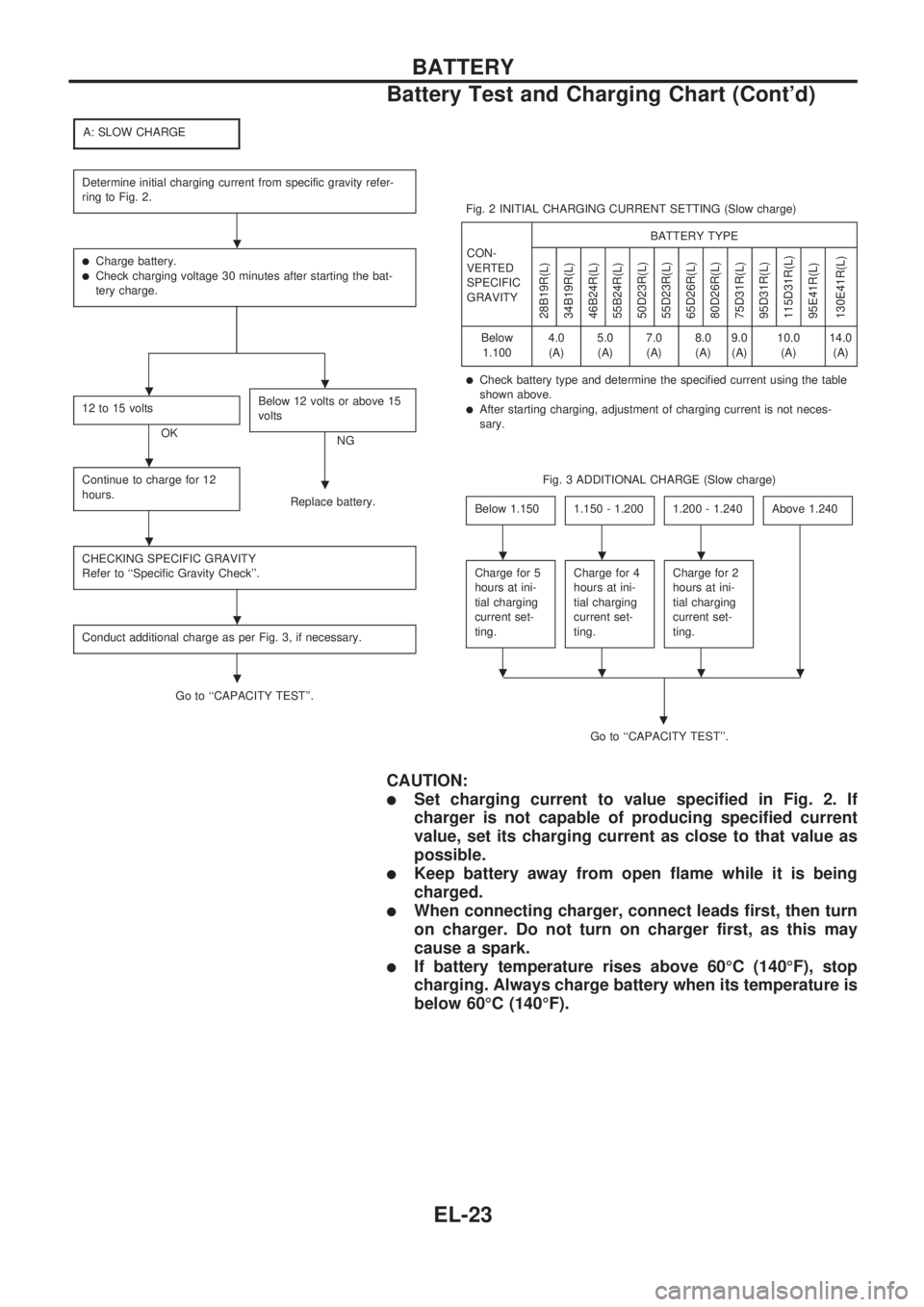
A: SLOW CHARGE
Determine initial charging current from specific gravity refer-
ring to Fig. 2.
lCharge battery.lCheck charging voltage 30 minutes after starting the bat-
tery charge.
12 to 15 volts
OKBelow 12 volts or above 15
voltsNG
Continue to charge for 12
hours.
Replace battery.
CHECKING SPECIFIC GRAVITY
Refer to ``Specific Gravity Check''.
Conduct additional charge as per Fig. 3, if necessary.
Go to ``CAPACITY TEST''.Fig. 2 INITIAL CHARGING CURRENT SETTING (Slow charge)
CON-
VERTED
SPECIFIC
GRAVITYBATTERY TYPE
28B19R(L)
34B19R(L)
46B24R(L)
55B24R(L)
50D23R(L)
55D23R(L)
65D26R(L)
80D26R(L)
75D31R(L)
95D31R(L)
115D31R(L)
95E41R(L)
130E41R(L)
Below
1.1004.0
(A)5.0
(A)7.0
(A)8.0
(A)9.0
(A)10.0
(A)14.0
(A)
lCheck battery type and determine the specified current using the table
shown above.
lAfter starting charging, adjustment of charging current is not neces-
sary.
Fig. 3 ADDITIONAL CHARGE (Slow charge)
Below 1.150
1.150 - 1.2001.200 - 1.240Above 1.240
Charge for 5
hours at ini-
tial charging
current set-
ting.Charge for 4
hours at ini-
tial charging
current set-
ting.Charge for 2
hours at ini-
tial charging
current set-
ting.
Go to ``CAPACITY TEST''.
.
CAUTION:
lSet charging current to value specified in Fig. 2. If
charger is not capable of producing specified current
value, set its charging current as close to that value as
possible.
lKeep battery away from open flame while it is being
charged.
lWhen connecting charger, connect leads first, then turn
on charger. Do not turn on charger first, as this may
cause a spark.
lIf battery temperature rises above 60ÉC (140ÉF), stop
charging. Always charge battery when its temperature is
below 60ÉC (140ÉF).
.
..
.
.
.
.
.
...
....
BATTERY
Battery Test and Charging Chart (Cont'd)
EL-23
Page 414 of 1659
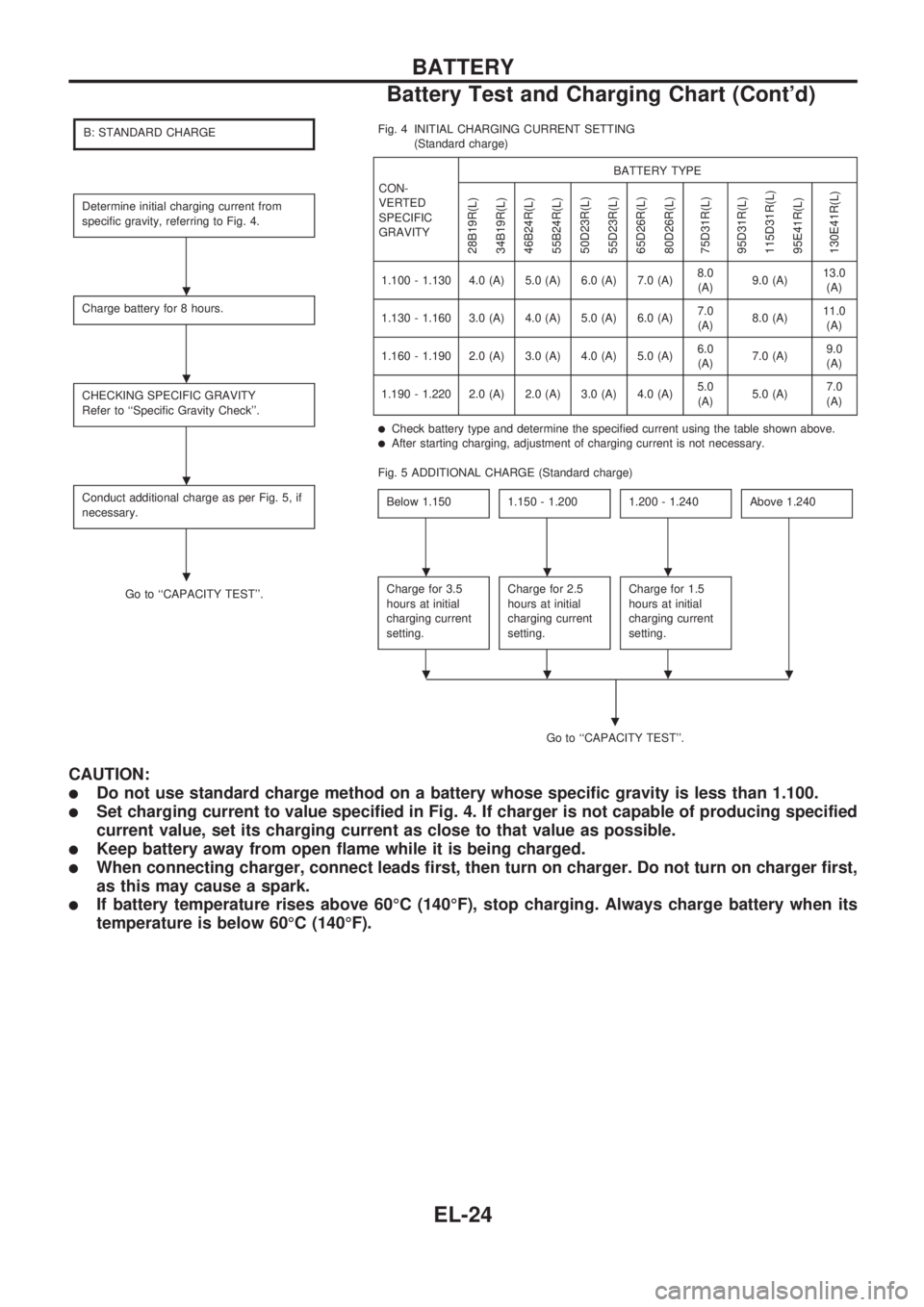
B: STANDARD CHARGE
Determine initial charging current from
specific gravity, referring to Fig. 4.
Charge battery for 8 hours.
CHECKING SPECIFIC GRAVITY
Refer to ``Specific Gravity Check''.
Conduct additional charge as per Fig. 5, if
necessary.
Go to ``CAPACITY TEST''.Fig. 4 INITIAL CHARGING CURRENT SETTING
(Standard charge)
CON-
VERTED
SPECIFIC
GRAVITYBATTERY TYPE
28B19R(L)
34B19R(L)
46B24R(L)
55B24R(L)
50D23R(L)
55D23R(L)
65D26R(L)
80D26R(L)
75D31R(L)
95D31R(L)
115D31R(L)
95E41R(L)
130E41R(L)
1.100 - 1.130 4.0 (A) 5.0 (A) 6.0 (A) 7.0 (A)8.0
(A)9.0 (A)13.0
(A)
1.130 - 1.160 3.0 (A) 4.0 (A) 5.0 (A) 6.0 (A)7.0
(A)8.0 (A)11.0
(A)
1.160 - 1.190 2.0 (A) 3.0 (A) 4.0 (A) 5.0 (A)6.0
(A)7.0 (A)9.0
(A)
1.190 - 1.220 2.0 (A) 2.0 (A) 3.0 (A) 4.0 (A)5.0
(A)5.0 (A)7.0
(A)
lCheck battery type and determine the specified current using the table shown above.lAfter starting charging, adjustment of charging current is not necessary.
Fig. 5 ADDITIONAL CHARGE (Standard charge)
Below 1.150
1.150 - 1.2001.200 - 1.240Above 1.240
Charge for 3.5
hours at initial
charging current
setting.Charge for 2.5
hours at initial
charging current
setting.Charge for 1.5
hours at initial
charging current
setting.
Go to ``CAPACITY TEST''.
.
CAUTION:
lDo not use standard charge method on a battery whose specific gravity is less than 1.100.
lSet charging current to value specified in Fig. 4. If charger is not capable of producing specified
current value, set its charging current as close to that value as possible.
lKeep battery away from open flame while it is being charged.
lWhen connecting charger, connect leads first, then turn on charger. Do not turn on charger first,
as this may cause a spark.
lIf battery temperature rises above 60ÉC (140ÉF), stop charging. Always charge battery when its
temperature is below 60ÉC (140ÉF).
.
.
.
....
....
BATTERY
Battery Test and Charging Chart (Cont'd)
EL-24