1998 NISSAN PICK-UP stop start
[x] Cancel search: stop startPage 211 of 1659
VA
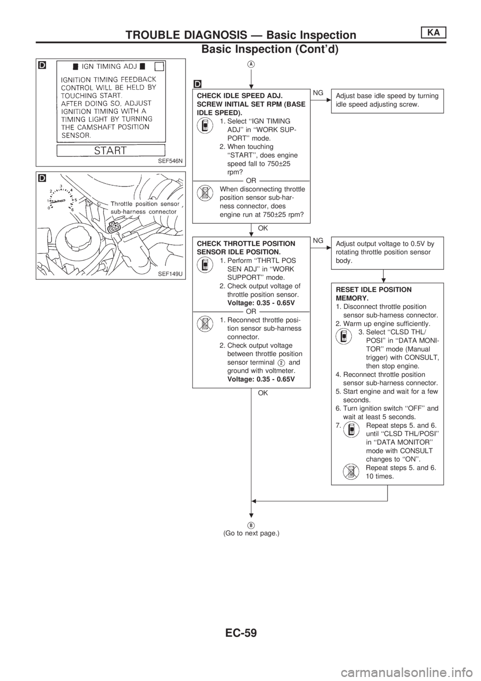
CHECK IDLE SPEED ADJ.
SCREW INITIAL SET RPM (BASE
IDLE SPEED).
1. Select ``IGN TIMING
ADJ'' in ``WORK SUP-
PORT'' mode.
2. When touching
``START'', does engine
speed fall to 750 25
rpm?
-----------------------------------------------------------------------------------------------------------OR -----------------------------------------------------------------------------------------------------------
When disconnecting throttle
position sensor sub-har-
ness connector, does
engine run at 750 25 rpm?
OK
cNG
Adjust base idle speed by turning
idle speed adjusting screw.
CHECK THROTTLE POSITION
SENSOR IDLE POSITION.
1. Perform ``THRTL POS
SEN ADJ'' in ``WORK
SUPPORT'' mode.
2. Check output voltage of
throttle position sensor.
Voltage: 0.35 - 0.65V
-----------------------------------------------------------------------------------------------------------OR -----------------------------------------------------------------------------------------------------------
1. Reconnect throttle posi-
tion sensor sub-harness
connector.
2. Check output voltage
between throttle position
sensor terminal
V2and
ground with voltmeter.
Voltage: 0.35 - 0.65V
OK
cNG
Adjust output voltage to 0.5V by
rotating throttle position sensor
body.
RESET IDLE POSITION
MEMORY.
1. Disconnect throttle position
sensor sub-harness connector.
2. Warm up engine sufficiently.
3. Select ``CLSD THL/
POSI'' in ``DATA MONI-
TOR'' mode (Manual
trigger) with CONSULT,
then stop engine.
4. Reconnect throttle position
sensor sub-harness connector.
5. Start engine and wait for a few
seconds.
6. Turn ignition switch ``OFF'' and
wait at least 5 seconds.
7.
Repeat steps 5. and 6.
until ``CLSD THL/POSI''
in ``DATA MONITOR''
mode with CONSULT
changes to ``ON''.
Repeat steps 5. and 6.
10 times.
b
VB
(Go to next page.)
SEF546N
SEF149U
.
.
.
.
TROUBLE DIAGNOSIS Ð Basic InspectionKA
Basic Inspection (Cont'd)
EC-59
Page 216 of 1659
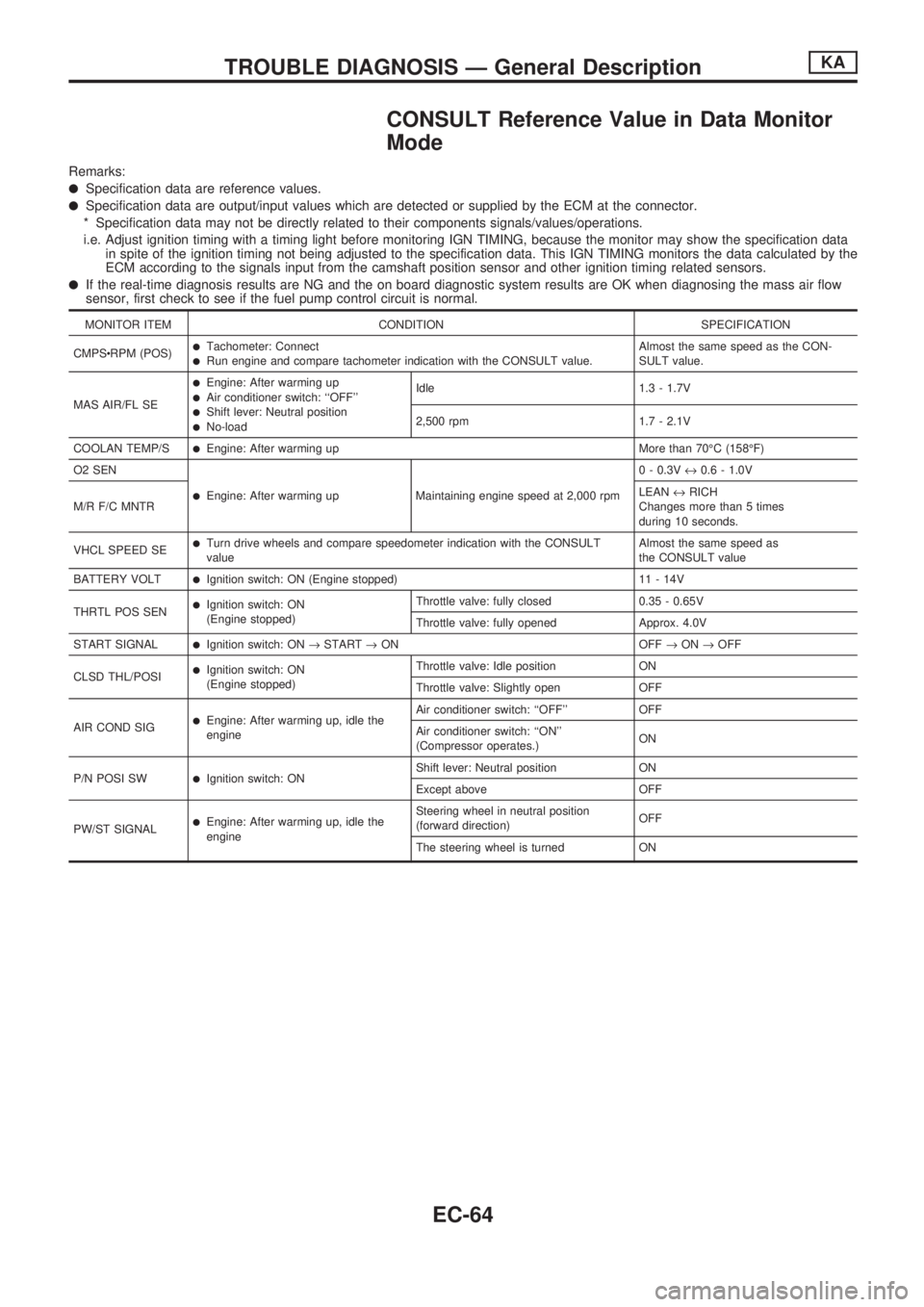
CONSULT Reference Value in Data Monitor
Mode
Remarks:
lSpecification data are reference values.
lSpecification data are output/input values which are detected or supplied by the ECM at the connector.
* Specification data may not be directly related to their components signals/values/operations.
i.e. Adjust ignition timing with a timing light before monitoring IGN TIMING, because the monitor may show the specification data
in spite of the ignition timing not being adjusted to the specification data. This IGN TIMING monitors the data calculated by the
ECM according to the signals input from the camshaft position sensor and other ignition timing related sensors.
lIf the real-time diagnosis results are NG and the on board diagnostic system results are OK when diagnosing the mass air flow
sensor, first check to see if the fuel pump control circuit is normal.
MONITOR ITEM CONDITION SPECIFICATION
CMPScRPM (POS)
lTachometer: ConnectlRun engine and compare tachometer indication with the CONSULT value.Almost the same speed as the CON-
SULT value.
MAS AIR/FL SE
lEngine: After warming uplAir conditioner switch: ``OFF''lShift lever: Neutral positionlNo-loadIdle 1.3 - 1.7V
2,500 rpm 1.7 - 2.1V
COOLAN TEMP/S
lEngine: After warming up More than 70ÉC (158ÉF)
O2 SEN
lEngine: After warming up Maintaining engine speed at 2,000 rpm0 - 0.3V«0.6 - 1.0V
M/R F/C MNTRLEAN«RICH
Changes more than 5 times
during 10 seconds.
VHCL SPEED SE
lTurn drive wheels and compare speedometer indication with the CONSULT
valueAlmost the same speed as
the CONSULT value
BATTERY VOLT
lIgnition switch: ON (Engine stopped) 11 - 14V
THRTL POS SEN
lIgnition switch: ON
(Engine stopped)Throttle valve: fully closed 0.35 - 0.65V
Throttle valve: fully opened Approx. 4.0V
START SIGNAL
lIgnition switch: ON®START®ON OFF®ON®OFF
CLSD THL/POSI
lIgnition switch: ON
(Engine stopped)Throttle valve: Idle position ON
Throttle valve: Slightly open OFF
AIR COND SIG
lEngine: After warming up, idle the
engineAir conditioner switch: ``OFF'' OFF
Air conditioner switch: ``ON''
(Compressor operates.)ON
P/N POSI SW
lIgnition switch: ONShift lever: Neutral position ON
Except above OFF
PW/ST SIGNAL
lEngine: After warming up, idle the
engineSteering wheel in neutral position
(forward direction)OFF
The steering wheel is turned ON
TROUBLE DIAGNOSIS Ð General DescriptionKA
EC-64
Page 232 of 1659
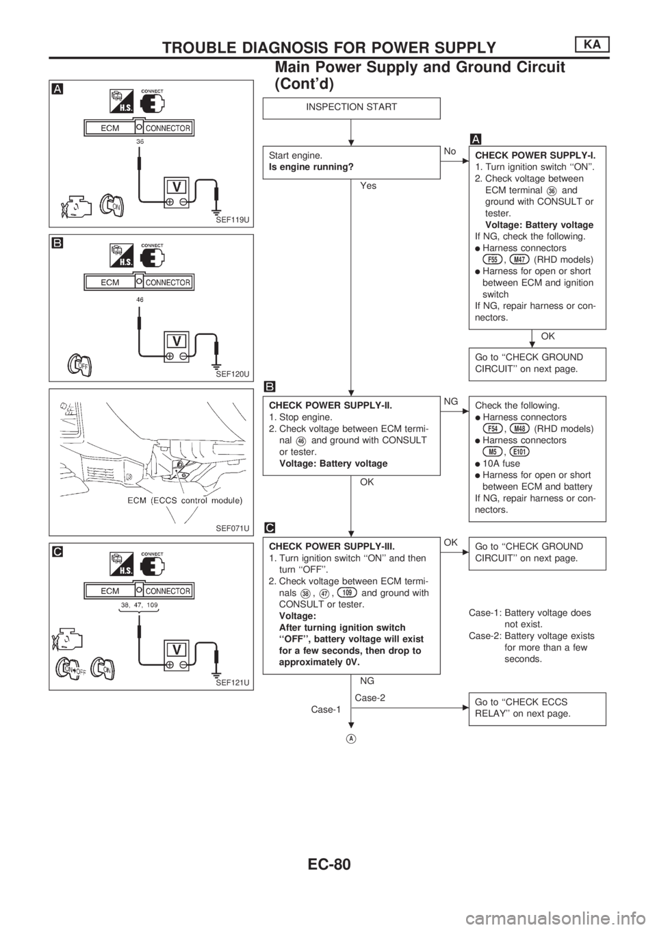
INSPECTION START
Start engine.
Is engine running?
Yes
cNo
CHECK POWER SUPPLY-I.
1. Turn ignition switch ``ON''.
2. Check voltage between
ECM terminal
V36and
ground with CONSULT or
tester.
Voltage: Battery voltage
If NG, check the following.
lHarness connectorsF55,M47(RHD models)
lHarness for open or short
between ECM and ignition
switch
If NG, repair harness or con-
nectors.
OK
Go to ``CHECK GROUND
CIRCUIT'' on next page.
CHECK POWER SUPPLY-II.
1. Stop engine.
2. Check voltage between ECM termi-
nal
V46and ground with CONSULT
or tester.
Voltage: Battery voltage
OK
cNG
Check the following.
lHarness connectorsF54,M48(RHD models)
lHarness connectorsM5,E101
l10A fuse
lHarness for open or short
between ECM and battery
If NG, repair harness or con-
nectors.
CHECK POWER SUPPLY-III.
1. Turn ignition switch ``ON'' and then
turn ``OFF''.
2. Check voltage between ECM termi-
nals
V38,V47,109and ground with
CONSULT or tester.
Voltage:
After turning ignition switch
``OFF'', battery voltage will exist
for a few seconds, then drop to
approximately 0V.
NG
cOK
Go to ``CHECK GROUND
CIRCUIT'' on next page.
Case-1: Battery voltage does
not exist.
Case-2: Battery voltage exists
for more than a few
seconds.
Case-1
cCase-2
Go to ``CHECK ECCS
RELAY'' on next page.
VA
SEF119U
SEF120U
SEF071U
SEF121U
.
.
.
.
.
TROUBLE DIAGNOSIS FOR POWER SUPPLYKA
Main Power Supply and Ground Circuit
(Cont'd)
EC-80
Page 246 of 1659
VA
CHECK COMPONENT
(Mass air flow sensor).
Refer to ``COMPONENT INSPECTION''
below.
OK
cNG
Replace mass air flow
sensor.
Disconnect and reconnect harness con-
nectors in the circuits. Then retest.
Trouble is not fixed.
Check ECM pin terminals for damage
and check the connection of ECM har-
ness connector. Reconnect ECM harness
connector and retest.
INSPECTION END
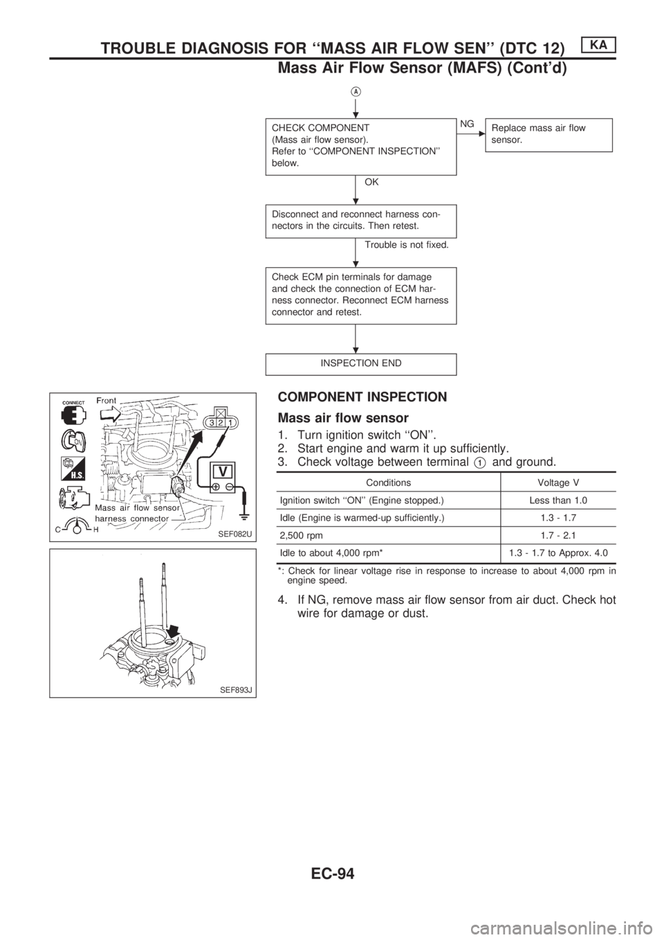
COMPONENT INSPECTION
Mass air flow sensor
1. Turn ignition switch ``ON''.
2. Start engine and warm it up sufficiently.
3. Check voltage between terminal
V1and ground.
Conditions Voltage V
Ignition switch ``ON'' (Engine stopped.) Less than 1.0
Idle (Engine is warmed-up sufficiently.) 1.3 - 1.7
2,500 rpm 1.7 - 2.1
Idle to about 4,000 rpm* 1.3 - 1.7 to Approx. 4.0
*: Check for linear voltage rise in response to increase to about 4,000 rpm in
engine speed.
4. If NG, remove mass air flow sensor from air duct. Check hot
wire for damage or dust.
SEF082U
SEF893J
.
.
.
.
TROUBLE DIAGNOSIS FOR ``MASS AIR FLOW SEN'' (DTC 12)KA
Mass Air Flow Sensor (MAFS) (Cont'd)
EC-94
Page 259 of 1659
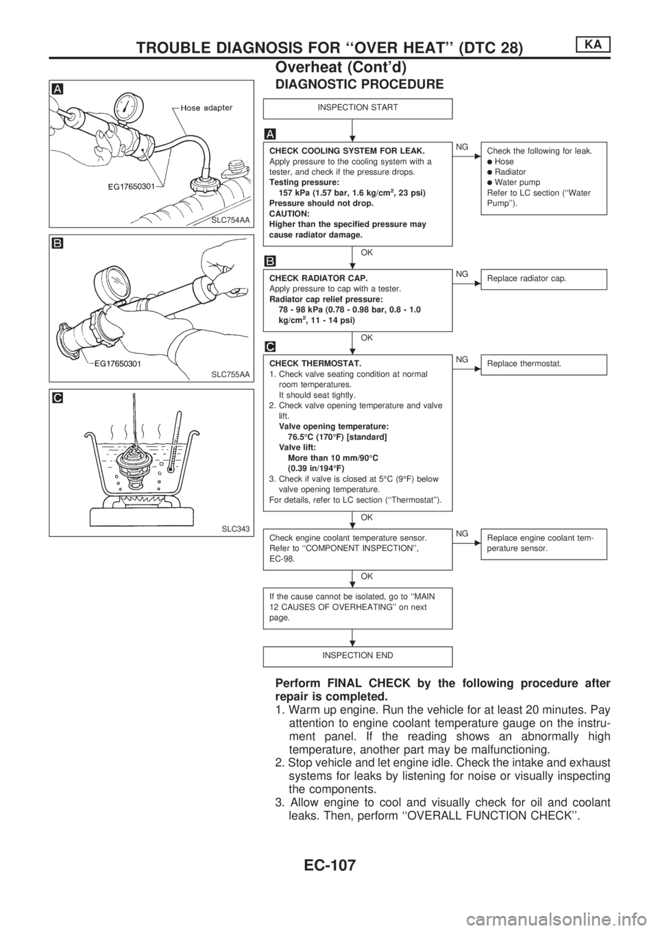
DIAGNOSTIC PROCEDURE
INSPECTION START
CHECK COOLING SYSTEM FOR LEAK.
Apply pressure to the cooling system with a
tester, and check if the pressure drops.
Testing pressure:
157 kPa (1.57 bar, 1.6 kg/cm
2, 23 psi)
Pressure should not drop.
CAUTION:
Higher than the specified pressure may
cause radiator damage.
OK
cNG
Check the following for leak.
lHoselRadiatorlWater pump
Refer to LC section (``Water
Pump'').
CHECK RADIATOR CAP.
Apply pressure to cap with a tester.
Radiator cap relief pressure:
78 - 98 kPa (0.78 - 0.98 bar, 0.8 - 1.0
kg/cm
2, 11 - 14 psi)
OK
cNG
Replace radiator cap.
CHECK THERMOSTAT.
1. Check valve seating condition at normal
room temperatures.
It should seat tightly.
2. Check valve opening temperature and valve
lift.
Valve opening temperature:
76.5ÉC (170ÉF) [standard]
Valve lift:
More than 10 mm/90ÉC
(0.39 in/194ÉF)
3. Check if valve is closed at 5ÉC (9ÉF) below
valve opening temperature.
For details, refer to LC section (``Thermostat'').
OK
cNG
Replace thermostat.
Check engine coolant temperature sensor.
Refer to ``COMPONENT INSPECTION'',
EC-98.
OK
cNG
Replace engine coolant tem-
perature sensor.
If the cause cannot be isolated, go to ``MAIN
12 CAUSES OF OVERHEATING'' on next
page.
INSPECTION END
Perform FINAL CHECK by the following procedure after
repair is completed.
1. Warm up engine. Run the vehicle for at least 20 minutes. Pay
attention to engine coolant temperature gauge on the instru-
ment panel. If the reading shows an abnormally high
temperature, another part may be malfunctioning.
2. Stop vehicle and let engine idle. Check the intake and exhaust
systems for leaks by listening for noise or visually inspecting
the components.
3. Allow engine to cool and visually check for oil and coolant
leaks. Then, perform ``OVERALL FUNCTION CHECK''.
SLC754AA
SLC755AA
SLC343
.
.
.
.
.
.
TROUBLE DIAGNOSIS FOR ``OVER HEAT'' (DTC 28)KA
Overheat (Cont'd)
EC-107
Page 277 of 1659
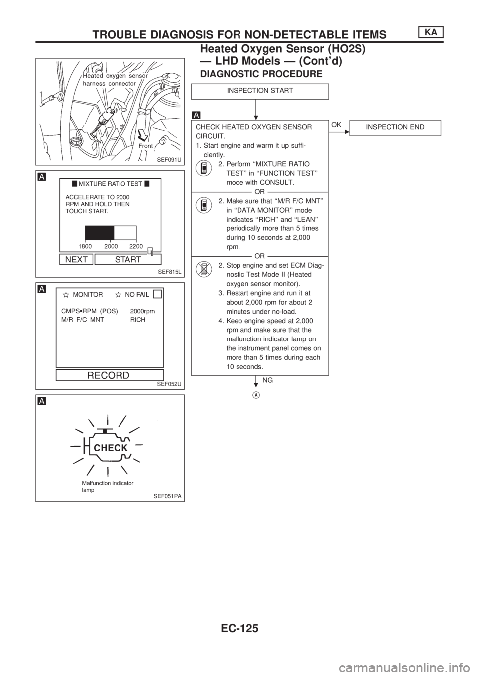
DIAGNOSTIC PROCEDURE
INSPECTION START
CHECK HEATED OXYGEN SENSOR
CIRCUIT.
1. Start engine and warm it up suffi-
ciently.
2. Perform ``MIXTURE RATIO
TEST'' in ``FUNCTION TEST''
mode with CONSULT.
----------------------------------------------------------------------------------------------------------------------------------OR----------------------------------------------------------------------------------------------------------------------------------
2. Make sure that ``M/R F/C MNT''
in ``DATA MONITOR'' mode
indicates ``RICH'' and ``LEAN''
periodically more than 5 times
during 10 seconds at 2,000
rpm.
----------------------------------------------------------------------------------------------------------------------------------OR----------------------------------------------------------------------------------------------------------------------------------
2. Stop engine and set ECM Diag-
nostic Test Mode II (Heated
oxygen sensor monitor).
3. Restart engine and run it at
about 2,000 rpm for about 2
minutes under no-load.
4. Keep engine speed at 2,000
rpm and make sure that the
malfunction indicator lamp on
the instrument panel comes on
more than 5 times during each
10 seconds.
NG
cOK
INSPECTION END
VA
SEF091U
SEF815L
SEF052U
SEF051PA
.
.
TROUBLE DIAGNOSIS FOR NON-DETECTABLE ITEMSKA
Heated Oxygen Sensor (HO2S)
Ð LHD Models Ð (Cont'd)
EC-125
Page 286 of 1659
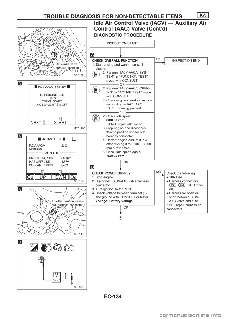
DIAGNOSTIC PROCEDURE
INSPECTION START
CHECK OVERALL FUNCTION.
1. Start engine and warm it up suffi-
ciently.
2. Perform ``IACV-AAC/V SYS-
TEM'' in ``FUNCTION TEST''
mode with CONSULT.
----------------------------------------------------------------------------------------------------------------------------------OR----------------------------------------------------------------------------------------------------------------------------------
2. Perform ``IACV-AAC/V OPEN-
ING'' in ``ACTIVE TEST'' mode
with CONSULT.
3. Check engine speed varies cor-
responding to IACV-AAC
VALVE opening percent.
----------------------------------------------------------------------------------------------------------------------------------OR----------------------------------------------------------------------------------------------------------------------------------
2. Check idle speed.
800 50 rpm
If NG, adjust idle speed.
3. Stop engine and disconnect
throttle position sensor sub-
harness connector.
4. Restart engine and let it idle
after revving it to 2,000 - 3,000
rpm a few times.
5. Check idle speed again.
750 25 rpm
NG
cOK
INSPECTION END
CHECK POWER SUPPLY.
1. Stop engine.
2. Disconnect IACV-AAC valve harness
connector.
3. Turn ignition switch ``ON''.
4. Check voltage between terminal
V3
and ground with CONSULT or tester.
Voltage: Battery voltage
OK
cNG
Check the following.
l10A fuse
lHarness connectorsF54,M48(RHD mod-
els)
lHarness for open or
short between IACV-
AAC valve and fuse
If NG, repair harness or
connectors.
VA
SEF152U
MEF176E
SEF164U
SEF148U
SEF095U
.
.
.
TROUBLE DIAGNOSIS FOR NON-DETECTABLE ITEMSKA
Idle Air Control Valve (IACV) Ð Auxiliary Air
Control (AAC) Valve (Cont'd)
EC-134
Page 299 of 1659
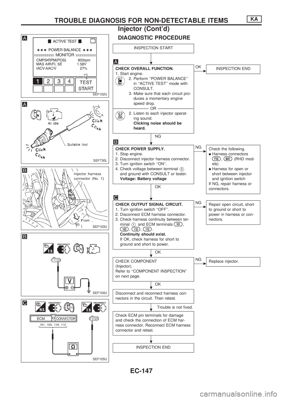
DIAGNOSTIC PROCEDURE
INSPECTION START
CHECK OVERALL FUNCTION.
1. Start engine.
2. Perform ``POWER BALANCE''
in ``ACTIVE TEST'' mode with
CONSULT.
3. Make sure that each circuit pro-
duces a momentary engine
speed drop.
----------------------------------------------------------------------------------------------------------------------------------OR----------------------------------------------------------------------------------------------------------------------------------
2. Listen to each injector operat-
ing sound.
Clicking noise should be
heard.
NG
cOK
INSPECTION END
CHECK POWER SUPPLY.
1. Stop engine.
2. Disconnect injector harness connector.
3. Turn ignition switch ``ON''.
4. Check voltage between terminal
V2
and ground with CONSULT or tester.
Voltage: Battery voltage
OK
cNG
Check the following.
lHarness connectorsF55,M47(RHD mod-
els)
lHarness for open or
short between injector
and ignition switch
If NG, repair harness or
connectors.
CHECK OUTPUT SIGNAL CIRCUIT.
1. Turn ignition switch ``OFF''.
2. Disconnect ECM harness connector.
3. Check harness continuity between ter-
minal
V1and ECM terminals101,103,110,112.
Continuity should exist.
If OK, check harness for short to
ground and short to power.
OK
cNG
Repair open circuit, short
to ground or short to
power in harness or con-
nectors.
CHECK COMPONENT
(Injector).
Refer to ``COMPONENT INSPECTION''
on next page.
OK
cNG
Replace injector.
Disconnect and reconnect harness con-
nectors in the circuit. Then retest.
Trouble is not fixed.
Check ECM pin terminals for damage
and check the connection of ECM har-
ness connector. Reconnect ECM harness
connector and retest.
INSPECTION END
SEF102U
SEF730L
SEF103U
SEF104U
SEF105U
.
.
.
.
.
.
.
TROUBLE DIAGNOSIS FOR NON-DETECTABLE ITEMSKA
Injector (Cont'd)
EC-147