1998 NISSAN PICK-UP stop start
[x] Cancel search: stop startPage 19 of 1659
On-vehicle Service
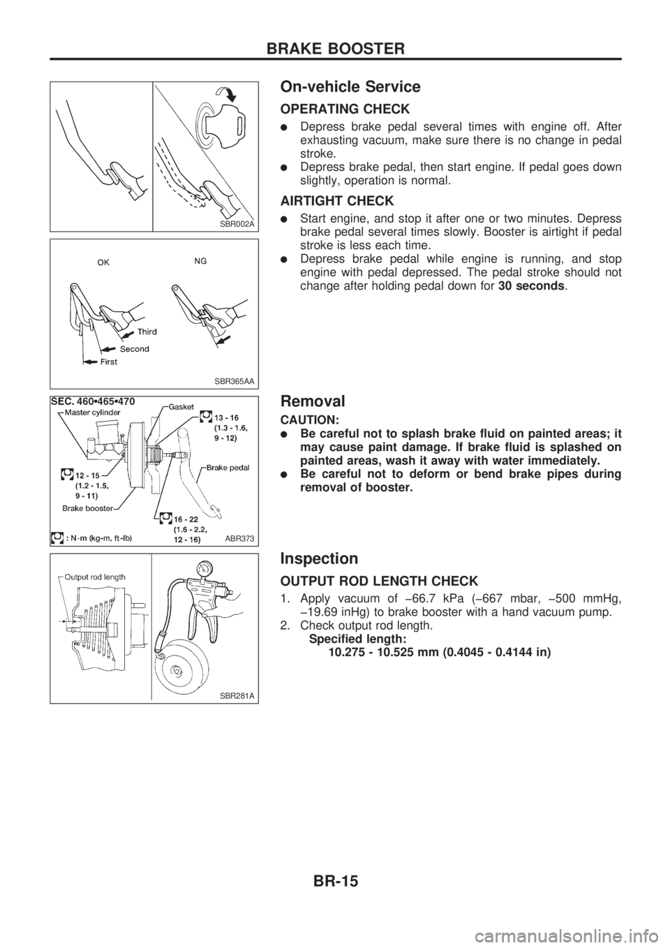
OPERATING CHECK
lDepress brake pedal several times with engine off. After
exhausting vacuum, make sure there is no change in pedal
stroke.
lDepress brake pedal, then start engine. If pedal goes down
slightly, operation is normal.
AIRTIGHT CHECK
lStart engine, and stop it after one or two minutes. Depress
brake pedal several times slowly. Booster is airtight if pedal
stroke is less each time.
lDepress brake pedal while engine is running, and stop
engine with pedal depressed. The pedal stroke should not
change after holding pedal down for30 seconds.
Removal
CAUTION:
lBe careful not to splash brake fluid on painted areas; it
may cause paint damage. If brake fluid is splashed on
painted areas, wash it away with water immediately.
lBe careful not to deform or bend brake pipes during
removal of booster.
Inspection
OUTPUT ROD LENGTH CHECK
1. Apply vacuum of þ66.7 kPa (þ667 mbar, þ500 mmHg,
þ19.69 inHg) to brake booster with a hand vacuum pump.
2. Check output rod length.
Specified length:
10.275 - 10.525 mm (0.4045 - 0.4144 in)
SBR002A
SBR365AA
ABR373
SBR281A
BRAKE BOOSTER
BR-15
Page 61 of 1659
CONSULT Inspection Procedure
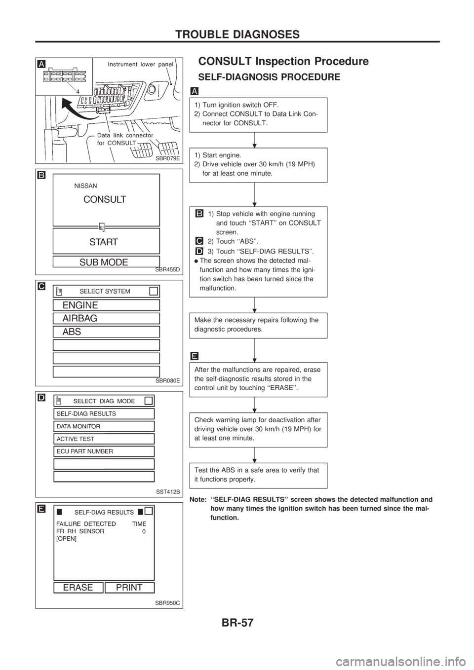
SELF-DIAGNOSIS PROCEDURE
1) Turn ignition switch OFF.
2) Connect CONSULT to Data Link Con-
nector for CONSULT.
1) Start engine.
2) Drive vehicle over 30 km/h (19 MPH)
for at least one minute.
1) Stop vehicle with engine running
and touch ``START'' on CONSULT
screen.
2) Touch ``ABS''.
3) Touch ``SELF-DIAG RESULTS''.
lThe screen shows the detected mal-
function and how many times the igni-
tion switch has been turned since the
malfunction.
Make the necessary repairs following the
diagnostic procedures.
After the malfunctions are repaired, erase
the self-diagnostic results stored in the
control unit by touching ``ERASE''.
Check warning lamp for deactivation after
driving vehicle over 30 km/h (19 MPH) for
at least one minute.
Test the ABS in a safe area to verify that
it functions properly.
Note: ``SELF-DIAG RESULTS'' screen shows the detected malfunction and
how many times the ignition switch has been turned since the mal-
function.
SBR079E
SBR455D
SBR080E
SST412B
SBR950C
.
.
.
.
.
.
TROUBLE DIAGNOSES
BR-57
Page 65 of 1659
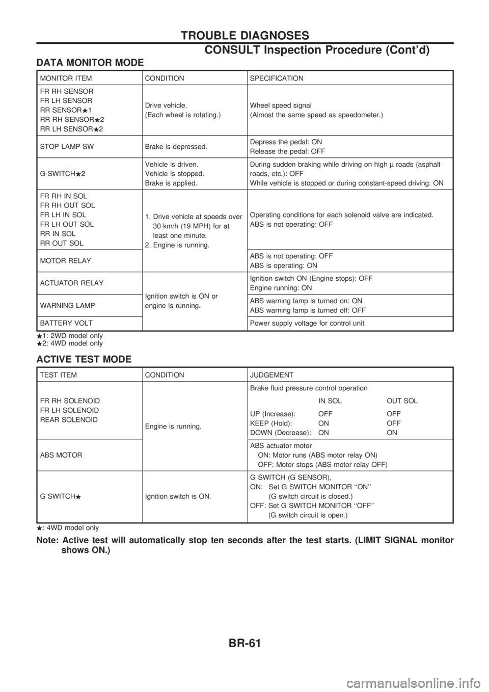
DATA MONITOR MODE
MONITOR ITEM CONDITION SPECIFICATION
FR RH SENSOR
FR LH SENSOR
RR SENSOR.1
RR RH SENSOR.2
RR LH SENSOR.2Drive vehicle.
(Each wheel is rotating.)Wheel speed signal
(Almost the same speed as speedometer.)
STOP LAMP SW Brake is depressed.Depress the pedal: ON
Release the pedal: OFF
G-SWITCH.2Vehicle is driven.
Vehicle is stopped.
Brake is applied.During sudden braking while driving on high roads (asphalt
roads, etc.): OFF
While vehicle is stopped or during constant-speed driving: ON
FR RH IN SOL
FR RH OUT SOL
FR LH IN SOL
FR LH OUT SOL
RR IN SOL
RR OUT SOL1. Drive vehicle at speeds over
30 km/h (19 MPH) for at
least one minute.
2. Engine is running.Operating conditions for each solenoid valve are indicated.
ABS is not operating: OFF
MOTOR RELAYABS is not operating: OFF
ABS is operating: ON
ACTUATOR RELAY
Ignition switch is ON or
engine is running.Ignition switch ON (Engine stops): OFF
Engine running: ON
WARNING LAMPABS warning lamp is turned on: ON
ABS warning lamp is turned off: OFF
BATTERY VOLT Power supply voltage for control unit
.1: 2WD model only
.2: 4WD model only
ACTIVE TEST MODE
TEST ITEM CONDITION JUDGEMENT
FR RH SOLENOID
FR LH SOLENOID
REAR SOLENOID
Engine is running.Brake fluid pressure control operation
IN SOL OUT SOL
UP (Increase):
KEEP (Hold):
DOWN (Decrease):OFF
ON
ONOFF
OFF
ON
ABS MOTORABS actuator motor
ON: Motor runs (ABS motor relay ON)
OFF: Motor stops (ABS motor relay OFF)
G SWITCH.Ignition switch is ON.G SWITCH (G SENSOR),
ON: Set G SWITCH MONITOR ``ON''
(G switch circuit is closed.)
OFF: Set G SWITCH MONITOR ``OFF''
(G switch circuit is open.)
.: 4WD model only
Note: Active test will automatically stop ten seconds after the test starts. (LIMIT SIGNAL monitor
shows ON.)
TROUBLE DIAGNOSES
CONSULT Inspection Procedure (Cont'd)
BR-61
Page 167 of 1659

MIXTURE RATIO FEEDBACK CONTROL
The mixture ratio feedback system provides the best air-fuel
mixture ratio for driveability and emission control. The three way
catalyst can then better reduce CO, HC and NOx emissions. This
system uses a heated oxygen sensor in the exhaust manifold to
monitor if the engine is rich or lean. The ECM adjusts the injec-
tion pulse width according to the sensor voltage signal. For more
information about heated oxygen sensor, refer to page EC-123.
This maintains the mixture ratio within the range of stoichiomet-
ric (ideal air-fuel mixture).
This stage is referred to as the closed loop control condition.
OPEN LOOP CONTROL
The open loop system condition refers to when the ECM detects
any of the following conditions. Feedback control stops in order
to maintain stabilized fuel combustion.
lDeceleration and acceleration
lHigh-load, high-speed operation
lEngine idling
lMalfunction of heated oxygen sensor or its circuit
lInsufficient activation of heated oxygen sensor at low engine
coolant temperature
lHigh-engine coolant temperature
lDuring warm-up
lWhen starting the engine
MIXTURE RATIO SELF-LEARNING CONTROL
The mixture ratio feedback control system monitors the mixture
ratio signal transmitted from the heated oxygen sensor. This
feedback signal is then sent to the ECM. The ECM controls the
basic mixture ratio as close to the theoretical mixture ratio as
possible. However, the basic mixture ratio is not necessarily con-
trolled as originally designed. Both Manufacturing differences
(i.e. mass air flow sensor hot wire) and characteristic changes
during operation (i.e. injector clogging) directly affect mixture
ratio.
Accordingly, the difference between the basic and theoretical
mixture ratios is monitored in this system. This is then computed
in terms of ``injection pulse duration'' to automatically compen-
sate for the difference between the two ratios.
FUEL INJECTION SYSTEM
Two types of systems are used.
Sequential multiport fuel injection system
Fuel is injected into each cylinder during each engine cycle
according to the firing order. This system is used when the
engine is running.
MEF025DD
MEF522D
ENGINE AND EMISSION BASIC CONTROL SYSTEM DESCRIPTIONKA
Multiport Fuel Injection (MFI) System
(Cont'd)
EC-15
Page 174 of 1659
Fuel Pressure Release
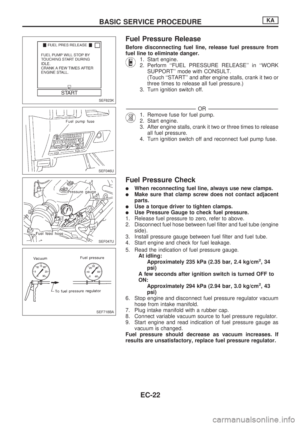
Before disconnecting fuel line, release fuel pressure from
fuel line to eliminate danger.
1. Start engine.
2. Perform ``FUEL PRESSURE RELEASE'' in ``WORK
SUPPORT'' mode with CONSULT.
(Touch ``START'' and after engine stalls, crank it two or
three times to release all fuel pressure.)
3. Turn ignition switch off.
-------------------------------------------------------------------------------------------------------------------------------------------------------------------------------------------------------------------------------------------------OR-------------------------------------------------------------------------------------------------------------------------------------------------------------------------------------------------------------------------------------------------
1. Remove fuse for fuel pump.
2. Start engine.
3. After engine stalls, crank it two or three times to release
all fuel pressure.
4. Turn ignition switch off and reconnect fuel pump fuse.
Fuel Pressure Check
lWhen reconnecting fuel line, always use new clamps.
lMake sure that clamp screw does not contact adjacent
parts.
lUse a torque driver to tighten clamps.
lUse Pressure Gauge to check fuel pressure.
1. Release fuel pressure to zero, refer to above.
2. Disconnect fuel hose between fuel filter and fuel tube (engine
side).
3. Install pressure gauge between fuel filter and fuel tube.
4. Start engine and check for fuel leakage.
5. Read the indication of fuel pressure gauge.
At idling:
Approximately 235 kPa (2.35 bar, 2.4 kg/cm
2,34
psi)
A few seconds after ignition switch is turned OFF to
ON:
Approximately 294 kPa (2.94 bar, 3.0 kg/cm
2,43
psi)
6. Stop engine and disconnect fuel pressure regulator vacuum
hose from intake manifold.
7. Plug intake manifold with a rubber cap.
8. Connect variable vacuum source to fuel pressure regulator.
9. Start engine and read indication of fuel pressure gauge as
vacuum is changed.
Fuel pressure should decrease as vacuum increases. If
results are unsatisfactory, replace fuel pressure regulator.
SEF823K
SEF046U
SEF047U
SEF718BA
BASIC SERVICE PROCEDUREKA
EC-22
Page 178 of 1659

START
Visually check the following:lAir cleaner clogginglHoses and ducts for leakslElectrical connectorslGasketlThrottle valve and throttle position sensor operations
Start engine and warm it up until engine coolant temperature
indicator points to the middle of gauge and ensure that engine
speed is below 1,000 rpm.
Open engine hood and run engine at about 2,000 rpm for about
2 minutes under no-load.
Perform the diagnostic test mode II (Self-diagnostic results).
OKNG
Repair or replace components as necessary.
.
Run engine at about 2,000 rpm for about 2 minutes under no-
load.
Rev engine two or three times under no-load, then run engine for
about 1 minute at idle speed.
1. Select ``IGNITION TIMING ADJ'' in WORK SUPPORT
mode.
2. Touch ``START''.
----------------------------------------------------------------------------------------------------------------------------------------------------------------------------------------------------------------OR----------------------------------------------------------------------------------------------------------------------------------------------------------------------------------------------------------------
1. Stop engine and disconnect throttle position sensor
harness connector.
2. Start engine.
Rev engine (2,000 - 3,000 rpm) 2 or 3 times under no-load and
run engine at idle speed.
Check ignition timing with a timing light.
---------------------------------------------------------------------------------------------------------------------------------------------------------------------------------------------------------------------------------------------------------------------------------------------------------------------------------------------------------------------------------------------------------------------------------------------------------------------
10É 2É BTDC
OK NG
VAVB
SEF146U
SEF247F
SEF051PA
SEF248F
SEF546N
.
.
.
.
.
.
.
.
.
..
BASIC SERVICE PROCEDUREKA
Idle Speed/Ignition Timing/Idle Mixture Ratio
Adjustment (Cont'd)
EC-26
Page 179 of 1659
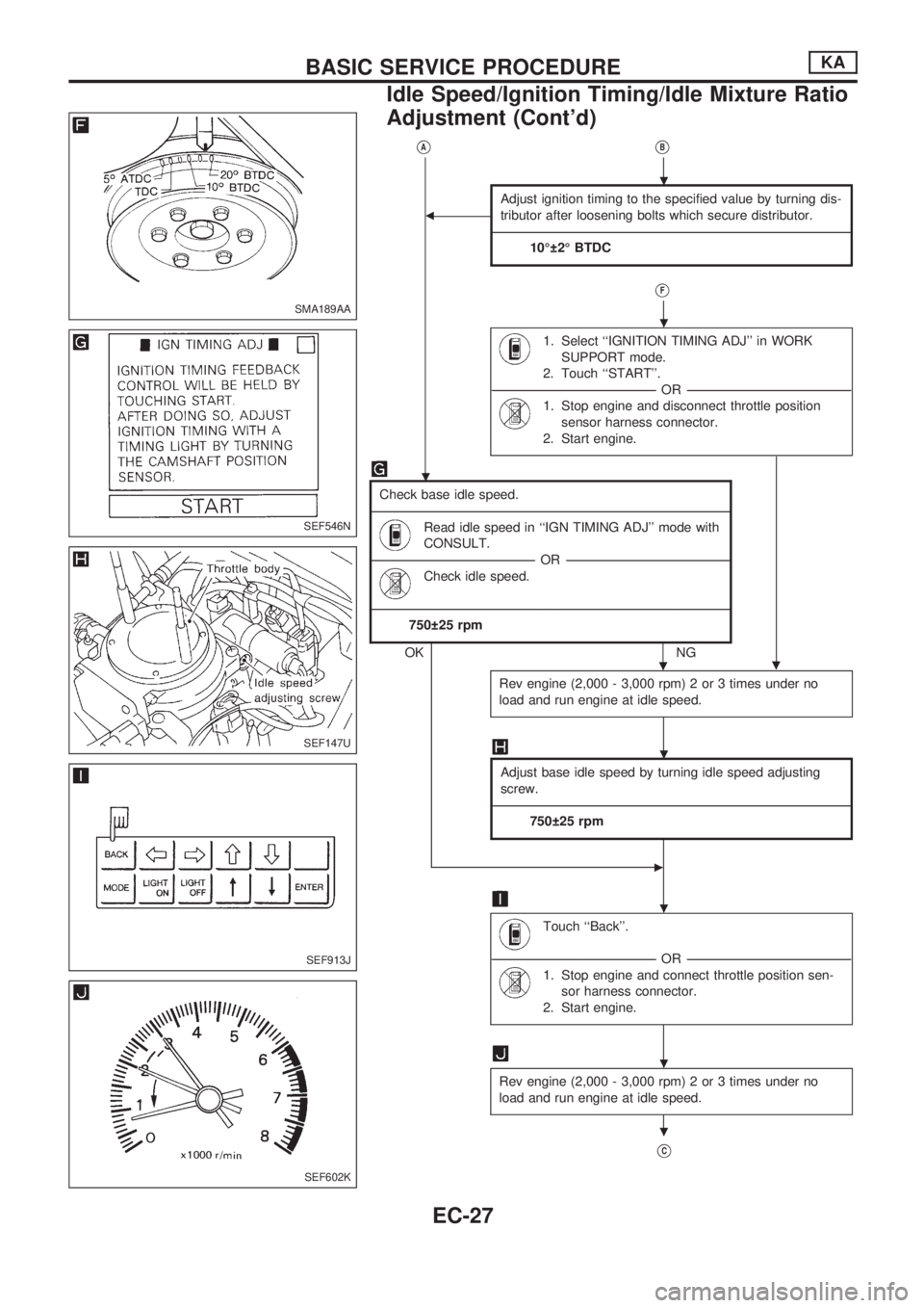
VAVB
b
Adjust ignition timing to the specified value by turning dis-
tributor after loosening bolts which secure distributor.
---------------------------------------------------------------------------------------------------------------------------------------------------------------------------------------------------------------------------------------------------------------------------------------------------------------------------------------------------------------------------------------------------------------------
10É 2É BTDC
VF
1. Select ``IGNITION TIMING ADJ'' in WORK
SUPPORT mode.
2. Touch ``START''.
----------------------------------------------------------------------------------------------------------------------------------------------------------------------------------------OR ----------------------------------------------------------------------------------------------------------------------------------------------------------------------------------------
1. Stop engine and disconnect throttle position
sensor harness connector.
2. Start engine.
.
Check base idle speed.
---------------------------------------------------------------------------------------------------------------------------------------------------------------------------------------------------------------------------------------------------------------------------------------------------------------------------------------------------------------------------------------------------------------------
Read idle speed in ``IGN TIMING ADJ'' mode with
CONSULT.
----------------------------------------------------------------------------------------------------------------------------------------------------------------------------------------OR ----------------------------------------------------------------------------------------------------------------------------------------------------------------------------------------
Check idle speed.
---------------------------------------------------------------------------------------------------------------------------------------------------------------------------------------------------------------------------------------------------------------------------------------------------------------------------------------------------------------------------------------------------------------------
750 25 rpm
OKNG
Rev engine (2,000 - 3,000 rpm) 2 or 3 times under no
load and run engine at idle speed.
Adjust base idle speed by turning idle speed adjusting
screw.
---------------------------------------------------------------------------------------------------------------------------------------------------------------------------------------------------------------------------------------------------------------------------------------------------------------------------------------------------------------------------------------------------------------------
750 25 rpm
c
Touch ``Back''.
----------------------------------------------------------------------------------------------------------------------------------------------------------------------------------------OR ----------------------------------------------------------------------------------------------------------------------------------------------------------------------------------------
1. Stop engine and connect throttle position sen-
sor harness connector.
2. Start engine.
Rev engine (2,000 - 3,000 rpm) 2 or 3 times under no
load and run engine at idle speed.
VC
SMA189AA
SEF546N
SEF147U
SEF913J
SEF602K
.
.
.
.
.
.
.
.
BASIC SERVICE PROCEDUREKA
Idle Speed/Ignition Timing/Idle Mixture Ratio
Adjustment (Cont'd)
EC-27
Page 184 of 1659
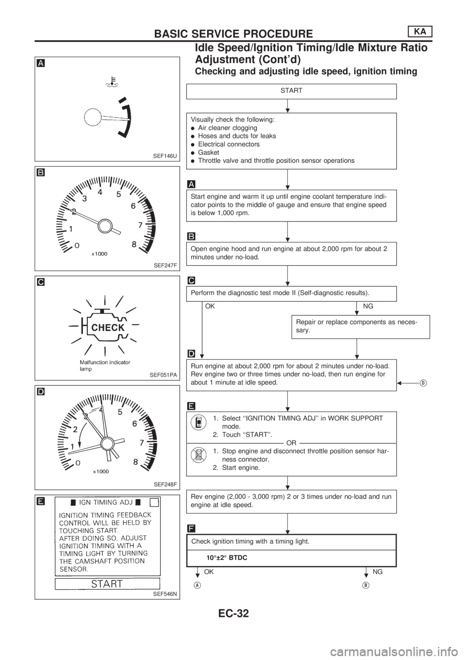
Checking and adjusting idle speed, ignition timing
START
Visually check the following:
lAir cleaner clogging
lHoses and ducts for leaks
lElectrical connectors
lGasket
lThrottle valve and throttle position sensor operations
Start engine and warm it up until engine coolant temperature indi-
cator points to the middle of gauge and ensure that engine speed
is below 1,000 rpm.
Open engine hood and run engine at about 2,000 rpm for about 2
minutes under no-load.
Perform the diagnostic test mode II (Self-diagnostic results).
OKNG
Repair or replace components as neces-
sary.
.
Run engine at about 2,000 rpm for about 2 minutes under no-load.
Rev engine two or three times under no-load, then run engine for
about 1 minute at idle speed.
bVD
1. Select ``IGNITION TIMING ADJ'' in WORK SUPPORT
mode.
2. Touch ``START''.
-----------------------------------------------------------------------------------------------------------------------------------------------------------------------------------------------------------------------OR -----------------------------------------------------------------------------------------------------------------------------------------------------------------------------------------------------------------------
1. Stop engine and disconnect throttle position sensor har-
ness connector.
2. Start engine.
Rev engine (2,000 - 3,000 rpm) 2 or 3 times under no-load and run
engine at idle speed.
Check ignition timing with a timing light.
------------------------------------------------------------------------------------------------------------------------------------------------------------------------------------------------------------------------------------------------------------------------------------------------------------------------------------------------------------------------------------------------------------------------------------------------------------------------------------
10É 2É BTDC
OK NG
VAVB
SEF146U
SEF247F
SEF051PA
SEF248F
SEF546N
.
.
.
.
.
.
.
.
.
..
BASIC SERVICE PROCEDUREKA
Idle Speed/Ignition Timing/Idle Mixture Ratio
Adjustment (Cont'd)
EC-32