Page 348 of 1659

Description
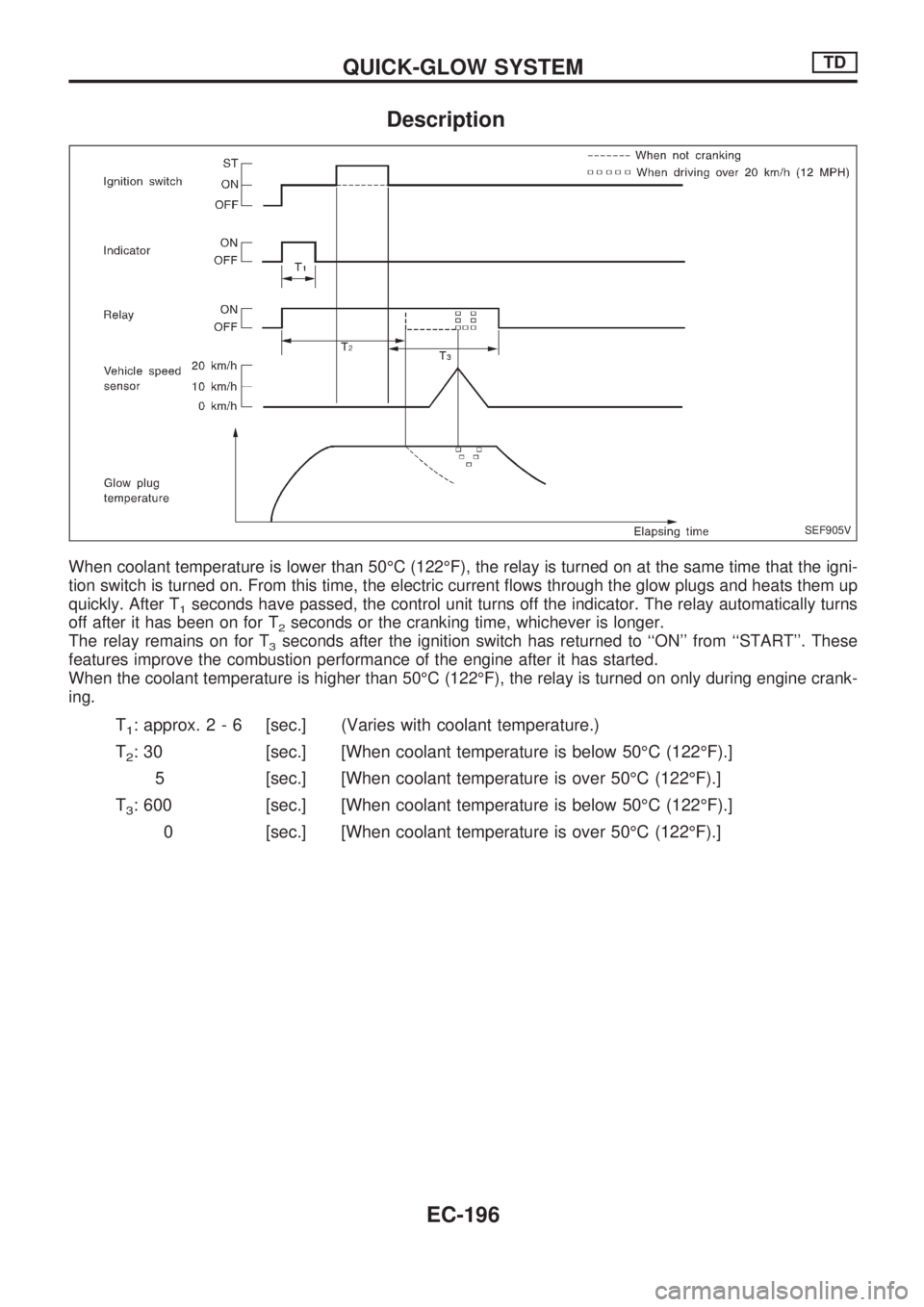
When coolant temperature is lower than 50ÉC (122ÉF), the relay is turned on at the same time that the igni-
tion switch is turned on. From this time, the electric current flows through the glow plugs and heats them up
quickly. After T
1seconds have passed, the control unit turns off the indicator. The relay automatically turns
off after it has been on for T
2seconds or the cranking time, whichever is longer.
The relay remains on for T
3seconds after the ignition switch has returned to ``ON'' from ``START''. These
features improve the combustion performance of the engine after it has started.
When the coolant temperature is higher than 50ÉC (122ÉF), the relay is turned on only during engine crank-
ing.
T1: approx.2-6[sec.] (Varies with coolant temperature.)
T
2: 30 [sec.] [When coolant temperature is below 50ÉC (122ÉF).]
5 [sec.] [When coolant temperature is over 50ÉC (122ÉF).]
T
3: 600 [sec.] [When coolant temperature is below 50ÉC (122ÉF).]
0 [sec.] [When coolant temperature is over 50ÉC (122ÉF).]
SEF905V
QUICK-GLOW SYSTEMTD
EC-196
Page 349 of 1659
Wiring Diagram
TD25 ENGINE (LHD)
HEC571
.
EC±GLOW±01
QUICK-GLOW SYSTEMTD
EC-197
Page 350 of 1659
TD25 ENGINE (LHD)
HEC572
.
EC±GLOW±02
QUICK-GLOW SYSTEMTD
Wiring Diagram (Cont'd)
EC-198
Page 351 of 1659
TD25 ENGINE (LHD)
HEC573
.
EC±GLOW±03
QUICK-GLOW SYSTEMTD
Wiring Diagram (Cont'd)
EC-199
Page 352 of 1659
TD25 ENGINE (RHD)
HEC574
.
EC±GLOW±04
QUICK-GLOW SYSTEMTD
Wiring Diagram (Cont'd)
EC-200
Page 353 of 1659
TD25 ENGINE (RHD)
HEC575
.
EC±GLOW±05
QUICK-GLOW SYSTEMTD
Wiring Diagram (Cont'd)
EC-201
Page 354 of 1659
TD25 ENGINE (RHD)
HEC576
.
EC±GLOW±06
QUICK-GLOW SYSTEMTD
Wiring Diagram (Cont'd)
EC-202
Page 355 of 1659
Glow Control Unit Circuit Inspection (For
Cold Areas)
Roll up the floor sheet. Check the glow control unit.
POWER SUPPLY CIRCUIT
Turn ignition switch ON and check voltage between terminalV1
orV11and body ground.
Voltage: approx. 12V
GROUND CIRCUIT
Check continuity between terminalV12,V13,V17orV18and body
ground.
Continuity should exist.
VEHICLE SPEED SENSOR CIRCUIT
While running vehicle or lifting rear wheels in 2WD position,
check that voltage between terminal
V10and body ground fluctu-
ates.
Voltage: approx. 5V
ENGINE COOLANT TEMPERATURE SENSOR
CIRCUIT
Check continuity between terminalsV21andV19orV20.
Measure resistance to temperature approximately as shown in
``ENGINE COOLANT TEMPERATURE SENSOR'', ``Component
Inspection'', EC-209.
DEF022-A
.
DEC044
DEC018
DEC019
DEC020
QUICK-GLOW SYSTEMTD
EC-203