1998 NISSAN PICK-UP engine
[x] Cancel search: enginePage 299 of 1659
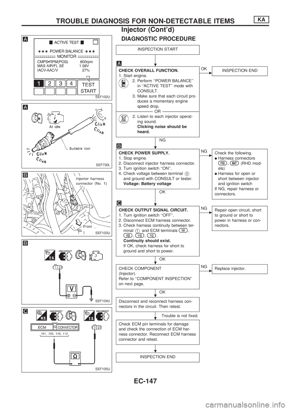
DIAGNOSTIC PROCEDURE
INSPECTION START
CHECK OVERALL FUNCTION.
1. Start engine.
2. Perform ``POWER BALANCE''
in ``ACTIVE TEST'' mode with
CONSULT.
3. Make sure that each circuit pro-
duces a momentary engine
speed drop.
----------------------------------------------------------------------------------------------------------------------------------OR----------------------------------------------------------------------------------------------------------------------------------
2. Listen to each injector operat-
ing sound.
Clicking noise should be
heard.
NG
cOK
INSPECTION END
CHECK POWER SUPPLY.
1. Stop engine.
2. Disconnect injector harness connector.
3. Turn ignition switch ``ON''.
4. Check voltage between terminal
V2
and ground with CONSULT or tester.
Voltage: Battery voltage
OK
cNG
Check the following.
lHarness connectorsF55,M47(RHD mod-
els)
lHarness for open or
short between injector
and ignition switch
If NG, repair harness or
connectors.
CHECK OUTPUT SIGNAL CIRCUIT.
1. Turn ignition switch ``OFF''.
2. Disconnect ECM harness connector.
3. Check harness continuity between ter-
minal
V1and ECM terminals101,103,110,112.
Continuity should exist.
If OK, check harness for short to
ground and short to power.
OK
cNG
Repair open circuit, short
to ground or short to
power in harness or con-
nectors.
CHECK COMPONENT
(Injector).
Refer to ``COMPONENT INSPECTION''
on next page.
OK
cNG
Replace injector.
Disconnect and reconnect harness con-
nectors in the circuit. Then retest.
Trouble is not fixed.
Check ECM pin terminals for damage
and check the connection of ECM har-
ness connector. Reconnect ECM harness
connector and retest.
INSPECTION END
SEF102U
SEF730L
SEF103U
SEF104U
SEF105U
.
.
.
.
.
.
.
TROUBLE DIAGNOSIS FOR NON-DETECTABLE ITEMSKA
Injector (Cont'd)
EC-147
Page 303 of 1659
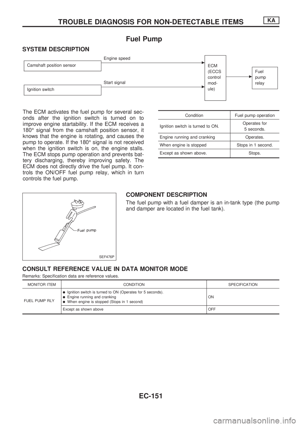
Fuel Pump
SYSTEM DESCRIPTION
Camshaft position sensorcEngine speed
ECM
(ECCS
control
mod-
ule)
cFuel
pump
relay
Ignition switchcStart signal
The ECM activates the fuel pump for several sec-
onds after the ignition switch is turned on to
improve engine startability. If the ECM receives a
180É signal from the camshaft position sensor, it
knows that the engine is rotating, and causes the
pump to operate. If the 180É signal is not received
when the ignition switch is on, the engine stalls.
The ECM stops pump operation and prevents bat-
tery discharging, thereby improving safety. The
ECM does not directly drive the fuel pump. It con-
trols the ON/OFF fuel pump relay, which in turn
controls the fuel pump.Condition Fuel pump operation
Ignition switch is turned to ON.Operates for
5 seconds.
Engine running and cranking Operates.
When engine is stopped Stops in 1 second.
Except as shown above. Stops.
COMPONENT DESCRIPTION
The fuel pump with a fuel damper is an in-tank type (the pump
and damper are located in the fuel tank).
CONSULT REFERENCE VALUE IN DATA MONITOR MODE
Remarks: Specification data are reference values.
MONITOR ITEM CONDITION SPECIFICATION
FUEL PUMP RLY
lIgnition switch is turned to ON (Operates for 5 seconds).lEngine running and crankinglWhen engine is stopped (Stops in 1 second)ON
Except as shown above OFF
SEF476P
TROUBLE DIAGNOSIS FOR NON-DETECTABLE ITEMSKA
EC-151
Page 304 of 1659
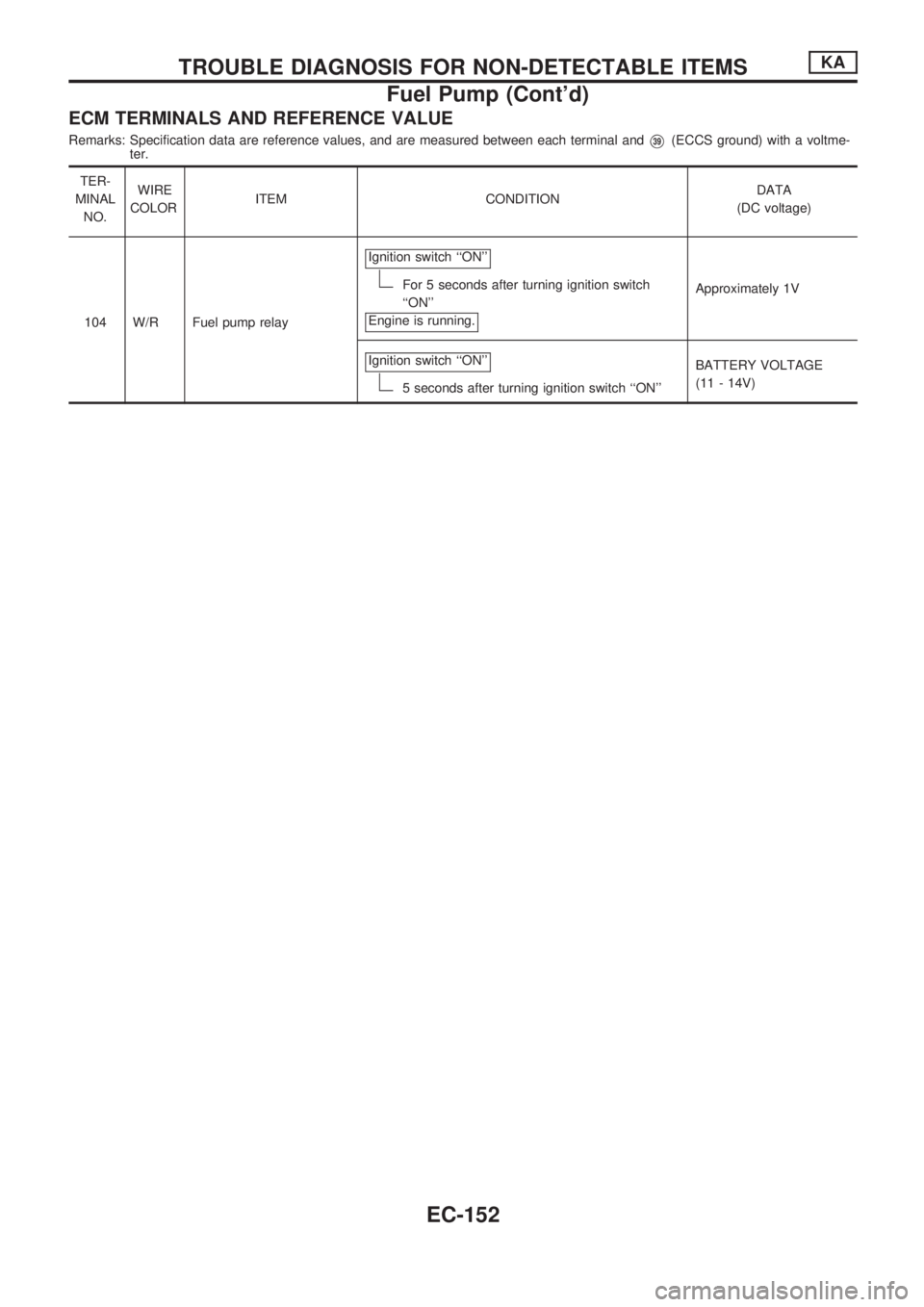
ECM TERMINALS AND REFERENCE VALUE
Remarks: Specification data are reference values, and are measured between each terminal andV39(ECCS ground) with a voltme-
ter.
TER-
MINAL
NO.WIRE
COLORITEM CONDITIONDATA
(DC voltage)
104 W/R Fuel pump relayIgnition switch ``ON''
For 5 seconds after turning ignition switch
``ON''
Engine is running.Approximately 1V
Ignition switch ``ON''
5 seconds after turning ignition switch ``ON''BATTERY VOLTAGE
(11 - 14V)
TROUBLE DIAGNOSIS FOR NON-DETECTABLE ITEMSKA
Fuel Pump (Cont'd)
EC-152
Page 310 of 1659
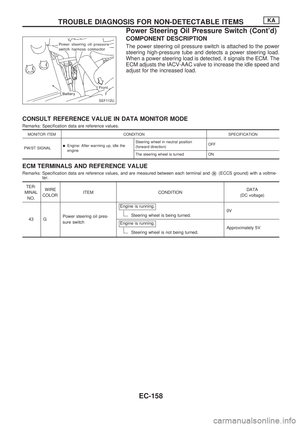
COMPONENT DESCRIPTION
The power steering oil pressure switch is attached to the power
steering high-pressure tube and detects a power steering load.
When a power steering load is detected, it signals the ECM. The
ECM adjusts the IACV-AAC valve to increase the idle speed and
adjust for the increased load.
CONSULT REFERENCE VALUE IN DATA MONITOR MODE
Remarks: Specification data are reference values.
MONITOR ITEM CONDITION SPECIFICATION
PW/ST SIGNAL
lEngine: After warming up, idle the
engineSteering wheel in neutral position
(forward direction)OFF
The steering wheel is turned ON
ECM TERMINALS AND REFERENCE VALUE
Remarks: Specification data are reference values, and are measured between each terminal andV39(ECCS ground) with a voltme-
ter.
TER-
MINAL
NO.WIRE
COLORITEM CONDITIONDATA
(DC voltage)
43 GPower steering oil pres-
sure switchEngine is running.
Steering wheel is being turned.0V
Engine is running.
Steering wheel is not being turned.Approximately 5V
SEF112U
TROUBLE DIAGNOSIS FOR NON-DETECTABLE ITEMSKA
Power Steering Oil Pressure Switch (Cont'd)
EC-158
Page 311 of 1659
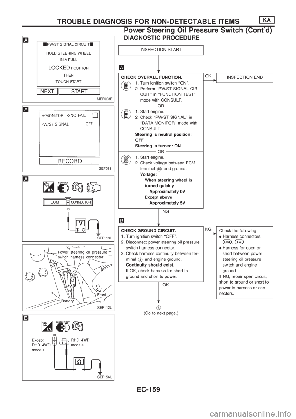
DIAGNOSTIC PROCEDURE
INSPECTION START
CHECK OVERALL FUNCTION.
1. Turn ignition switch ``ON''.
2. Perform ``PW/ST SIGNAL CIR-
CUIT'' in ``FUNCTION TEST''
mode with CONSULT.
----------------------------------------------------------------------------------------------------------------------------------OR----------------------------------------------------------------------------------------------------------------------------------
1. Start engine.
2. Check ``PW/ST SIGNAL'' in
``DATA MONITOR'' mode with
CONSULT.
Steering is neutral position:
OFF
Steering is turned: ON
----------------------------------------------------------------------------------------------------------------------------------OR----------------------------------------------------------------------------------------------------------------------------------
1. Start engine.
2. Check voltage between ECM
terminal
V43and ground.
Voltage:
When steering wheel is
turned quickly
Approximately 0V
Except above
Approximately 5V
NG
cOK
INSPECTION END
CHECK GROUND CIRCUIT.
1. Turn ignition switch ``OFF''.
2. Disconnect power steering oil pressure
switch harness connector.
3. Check harness continuity between ter-
minal
V2and engine ground.
Continuity should exist.
If OK, check harness for short to
ground and short to power.
OK
cNG
Check the following.
lHarness connectors
E204,E29
lHarness for open or
short between power
steering oil pressure
switch and engine
ground
If NG, repair open circuit,
short to ground or short to
power in harness or con-
nectors.
VA
(Go to next page.)
MEF023E
SEF591I
SEF113U
SEF112U
SEF156U
.
.
.
TROUBLE DIAGNOSIS FOR NON-DETECTABLE ITEMSKA
Power Steering Oil Pressure Switch (Cont'd)
EC-159
Page 312 of 1659
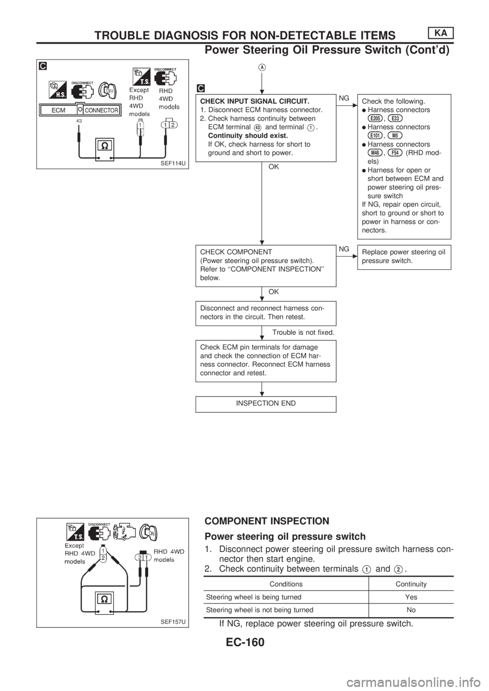
VA
CHECK INPUT SIGNAL CIRCUIT.
1. Disconnect ECM harness connector.
2. Check harness continuity between
ECM terminal
V43and terminalV1.
Continuity should exist.
If OK, check harness for short to
ground and short to power.
OK
cNG
Check the following.
lHarness connectorsE205,E33
lHarness connectorsE101,M5
lHarness connectorsM48,F54(RHD mod-
els)
lHarness for open or
short between ECM and
power steering oil pres-
sure switch
If NG, repair open circuit,
short to ground or short to
power in harness or con-
nectors.
CHECK COMPONENT
(Power steering oil pressure switch).
Refer to ``COMPONENT INSPECTION''
below.
OK
cNG
Replace power steering oil
pressure switch.
Disconnect and reconnect harness con-
nectors in the circuit. Then retest.
Trouble is not fixed.
Check ECM pin terminals for damage
and check the connection of ECM har-
ness connector. Reconnect ECM harness
connector and retest.
INSPECTION END
COMPONENT INSPECTION
Power steering oil pressure switch
1. Disconnect power steering oil pressure switch harness con-
nector then start engine.
2. Check continuity between terminals
V1andV2.
Conditions Continuity
Steering wheel is being turned Yes
Steering wheel is not being turned No
If NG, replace power steering oil pressure switch.
SEF114U
SEF157U
.
.
.
.
.
TROUBLE DIAGNOSIS FOR NON-DETECTABLE ITEMSKA
Power Steering Oil Pressure Switch (Cont'd)
EC-160
Page 313 of 1659
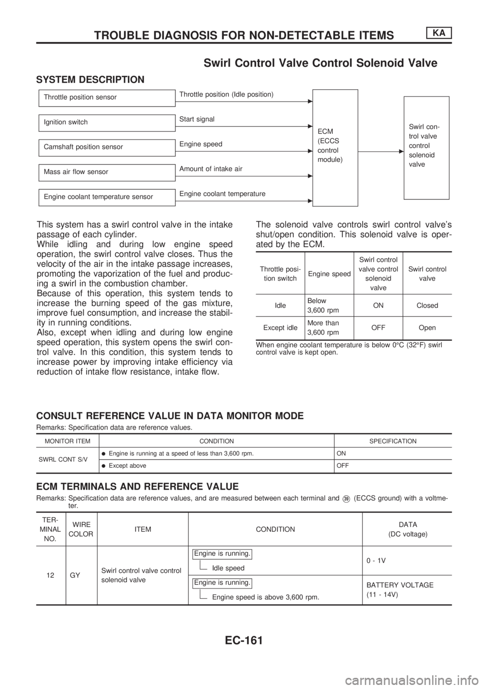
Swirl Control Valve Control Solenoid Valve
SYSTEM DESCRIPTION
Throttle position sensorcThrottle position (Idle position)
ECM
(ECCS
control
module)
c
Swirl con-
trol valve
control
solenoid
valveIgnition switchcStart signal
Camshaft position sensor
cEngine speed
Mass air flow sensor
cAmount of intake air
Engine coolant temperature sensor
cEngine coolant temperature
This system has a swirl control valve in the intake
passage of each cylinder.
While idling and during low engine speed
operation, the swirl control valve closes. Thus the
velocity of the air in the intake passage increases,
promoting the vaporization of the fuel and produc-
ing a swirl in the combustion chamber.
Because of this operation, this system tends to
increase the burning speed of the gas mixture,
improve fuel consumption, and increase the stabil-
ity in running conditions.
Also, except when idling and during low engine
speed operation, this system opens the swirl con-
trol valve. In this condition, this system tends to
increase power by improving intake efficiency via
reduction of intake flow resistance, intake flow.The solenoid valve controls swirl control valve's
shut/open condition. This solenoid valve is oper-
ated by the ECM.
Throttle posi-
tion switchEngine speedSwirl control
valve control
solenoid
valveSwirl control
valve
IdleBelow
3,600 rpmON Closed
Except idleMore than
3,600 rpmOFF Open
When engine coolant temperature is below 0ÉC (32ÉF) swirl
control valve is kept open.
CONSULT REFERENCE VALUE IN DATA MONITOR MODE
Remarks: Specification data are reference values.
MONITOR ITEM CONDITION SPECIFICATION
SWRL CONT S/V
lEngine is running at a speed of less than 3,600 rpm. ON
lExcept above OFF
ECM TERMINALS AND REFERENCE VALUE
Remarks: Specification data are reference values, and are measured between each terminal andV39(ECCS ground) with a voltme-
ter.
TER-
MINAL
NO.WIRE
COLORITEM CONDITIONDATA
(DC voltage)
12 GYSwirl control valve control
solenoid valveEngine is running.
Idle speed0-1V
Engine is running.
Engine speed is above 3,600 rpm.BATTERY VOLTAGE
(11 - 14V)
TROUBLE DIAGNOSIS FOR NON-DETECTABLE ITEMSKA
EC-161
Page 316 of 1659
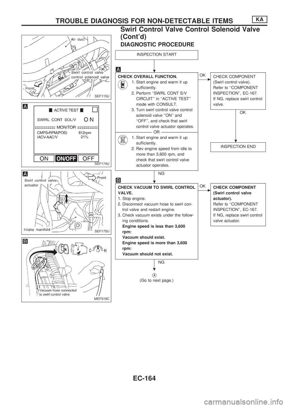
DIAGNOSTIC PROCEDURE
INSPECTION START
CHECK OVERALL FUNCTION.
1. Start engine and warm it up
sufficiently.
2. Perform ``SWRL CONT S/V
CIRCUIT'' in ``ACTIVE TEST''
mode with CONSULT.
3. Turn swirl control valve control
solenoid valve ``ON'' and
``OFF'', and check that swirl
control valve actuator operates.
----------------------------------------------------------------------------------------------------------------------------------OR----------------------------------------------------------------------------------------------------------------------------------
1. Start engine and warm it up
sufficiently.
2. Rev engine speed from idle to
more than 3,600 rpm, and
check that swirl control valve
actuator operates.
NG
cOK
CHECK COMPONENT
(Swirl control valve).
Refer to ``COMPONENT
INSPECTION'', EC-167.
If NG, replace swirl control
valve.
OK
INSPECTION END
CHECK VACUUM TO SWIRL CONTROL
VALVE.
1. Stop engine.
2. Disconnect vacuum hose to swirl con-
trol valve and restart engine.
3. Check vacuum exists under the follow-
ing conditions.
Engine speed is less than 3,600
rpm:
Vacuum should exist.
Engine speed is more than 3,600
rpm:
Vacuum should not exist.
NG
cOK
CHECK COMPONENT
(Swirl control valve
actuator).
Refer to ``COMPONENT
INSPECTION'', EC-167.
If NG, replace swirl control
valve actuator.
VA
(Go to next page.)
SEF115U
SEF174U
SEF175U
MEF519C
.
.
.
.
TROUBLE DIAGNOSIS FOR NON-DETECTABLE ITEMSKA
Swirl Control Valve Control Solenoid Valve
(Cont'd)
EC-164