Page 317 of 1659
VA
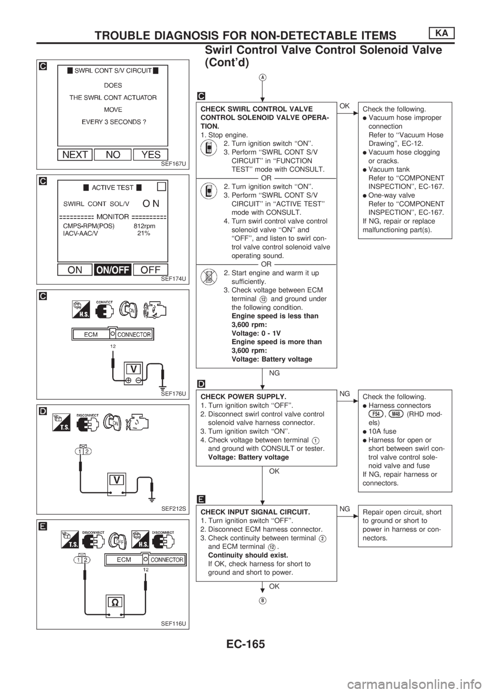
CHECK SWIRL CONTROL VALVE
CONTROL SOLENOID VALVE OPERA-
TION.
1. Stop engine.
2. Turn ignition switch ``ON''.
3. Perform ``SWRL CONT S/V
CIRCUIT'' in ``FUNCTION
TEST'' mode with CONSULT.
----------------------------------------------------------------------------------------------------------------------------------OR----------------------------------------------------------------------------------------------------------------------------------
2. Turn ignition switch ``ON''.
3. Perform ``SWRL CONT S/V
CIRCUIT'' in ``ACTIVE TEST''
mode with CONSULT.
4. Turn swirl control valve control
solenoid valve ``ON'' and
``OFF'', and listen to swirl con-
trol valve control solenoid valve
operating sound.
----------------------------------------------------------------------------------------------------------------------------------OR----------------------------------------------------------------------------------------------------------------------------------
2. Start engine and warm it up
sufficiently.
3. Check voltage between ECM
terminal
V12and ground under
the following condition.
Engine speed is less than
3,600 rpm:
Voltage:0-1V
Engine speed is more than
3,600 rpm:
Voltage: Battery voltage
NG
cOK
Check the following.
lVacuum hose improper
connection
Refer to ``Vacuum Hose
Drawing'', EC-12.
lVacuum hose clogging
or cracks.
lVacuum tank
Refer to ``COMPONENT
INSPECTION'', EC-167.
lOne-way valve
Refer to ``COMPONENT
INSPECTION'', EC-167.
If NG, repair or replace
malfunctioning part(s).
CHECK POWER SUPPLY.
1. Turn ignition switch ``OFF''.
2. Disconnect swirl control valve control
solenoid valve harness connector.
3. Turn ignition switch ``ON''.
4. Check voltage between terminal
V1
and ground with CONSULT or tester.
Voltage: Battery voltage
OK
cNG
Check the following.
lHarness connectorsF54,M48(RHD mod-
els)
l10A fuse
lHarness for open or
short between swirl con-
trol valve control sole-
noid valve and fuse
If NG, repair harness or
connectors.
CHECK INPUT SIGNAL CIRCUIT.
1. Turn ignition switch ``OFF''.
2. Disconnect ECM harness connector.
3. Check continuity between terminal
V2
and ECM terminalV12.
Continuity should exist.
If OK, check harness for short to
ground and short to power.
OK
cNG
Repair open circuit, short
to ground or short to
power in harness or con-
nectors.
VB
SEF167U
SEF174U
SEF176U
SEF212S
SEF116U
.
.
.
.
TROUBLE DIAGNOSIS FOR NON-DETECTABLE ITEMSKA
Swirl Control Valve Control Solenoid Valve
(Cont'd)
EC-165
Page 322 of 1659
COMPONENT DESCRIPTION
The idle air adjusting (IAA) unit is made up of the IACV-AAC
valve, IACV-FICD solenoid valve and idle adjusting screw. It
receives the signal from the ECM and controls the idle speed at
the preset value.
ECM TERMINALS AND REFERENCE VALUE
Remarks: Specification data are reference values and are measured between each terminal andV39(ECCS ground) with a voltme-
ter.
TER-
MINAL
NO.WIRE
COLORITEM CONDITIONDATA
(DC voltage)
11 G/R Air conditioner relayEngine is running.
Both air conditioner switch and blower switch
are ``ON''. (Compressor operates.)Approximately 1V
Engine is running.
Air conditioner switch is ``OFF''.BATTERY VOLTAGE
(11 - 14V)
41 Y Air conditioner switchEngine is running.
Both air conditioner switch and blower switch
are ``ON''. (Compressor operates.)Approximately 0V
Engine is running.
Air conditioner switch is ``OFF''.BATTERY VOLTAGE
(11 - 14V)
SEF158U
TROUBLE DIAGNOSIS FOR NON-DETECTABLE ITEMSKA
IACV-FICD Solenoid Valve (Cont'd)
EC-170
Page 323 of 1659
DIAGNOSTIC PROCEDURE
INSPECTION START
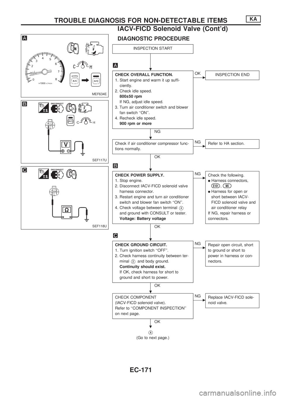
CHECK OVERALL FUNCTION.
1. Start engine and warm it up suffi-
ciently.
2. Check idle speed.
800 50 rpm
If NG, adjust idle speed.
3. Turn air conditioner switch and blower
fan switch ``ON''.
4. Recheck idle speed.
900 rpm or more
NG
cOK
INSPECTION END
Check if air conditioner compressor func-
tions normally.
OK
cNG
Refer to HA section.
CHECK POWER SUPPLY.
1. Stop engine.
2. Disconnect IACV-FICD solenoid valve
harness connector.
3. Restart engine and turn air conditioner
switch and blower fan switch ``ON''.
4. Check voltage between terminal
V4
and ground with CONSULT or tester.
Voltage: Battery voltage
OK
cNG
Check the following.
lHarness connectors,
E101,M5
lHarness for open or
short between IACV-
FICD solenoid valve and
air conditioner relay
If NG, repair harness or
connectors.
CHECK GROUND CIRCUIT.
1. Turn ignition switch ``OFF''.
2. Check harness continuity between ter-
minal
V2and body ground.
Continuity should exist.
If OK, check harness for short to
ground and short to power.
OK
cNG
Repair open circuit, short
to ground or short to
power in harness or con-
nectors.
CHECK COMPONENT
(IACV-FICD solenoid valve).
Refer to ``COMPONENT INSPECTION''
on next page.
OK
cNG
Replace IACV-FICD sole-
noid valve.
VA
(Go to next page.)
MEF634E
SEF117U
SEF118U
.
.
.
.
.
.
TROUBLE DIAGNOSIS FOR NON-DETECTABLE ITEMSKA
IACV-FICD Solenoid Valve (Cont'd)
EC-171
Page 328 of 1659
CAUTION:
lDisassembly and assembly of the injection pumps should be done only in service shops autho-
rized by NISSAN or by the pump manufacturer.
lThe pump tester is required for servicing the pump.
lBefore removing fuel injection pump from vehicle, check closely to make sure that it is definitely
malfunctioning.
For TD25 engine models with Nissan Anti-Theft System (NATS)
lFor inspection of coded solenoid unit (CSOLU), refer to NATS (Diesel) in EL section.
lWhen replacing injection pump assembly along with CSOLU, perform NATS initialisation with
CONSULT.
For initialisation procedure, refer to NATS (Diesel) in EL section.
Fuel System
SEF378RA
INJECTION SYSTEMTD
EC-176
Page 333 of 1659
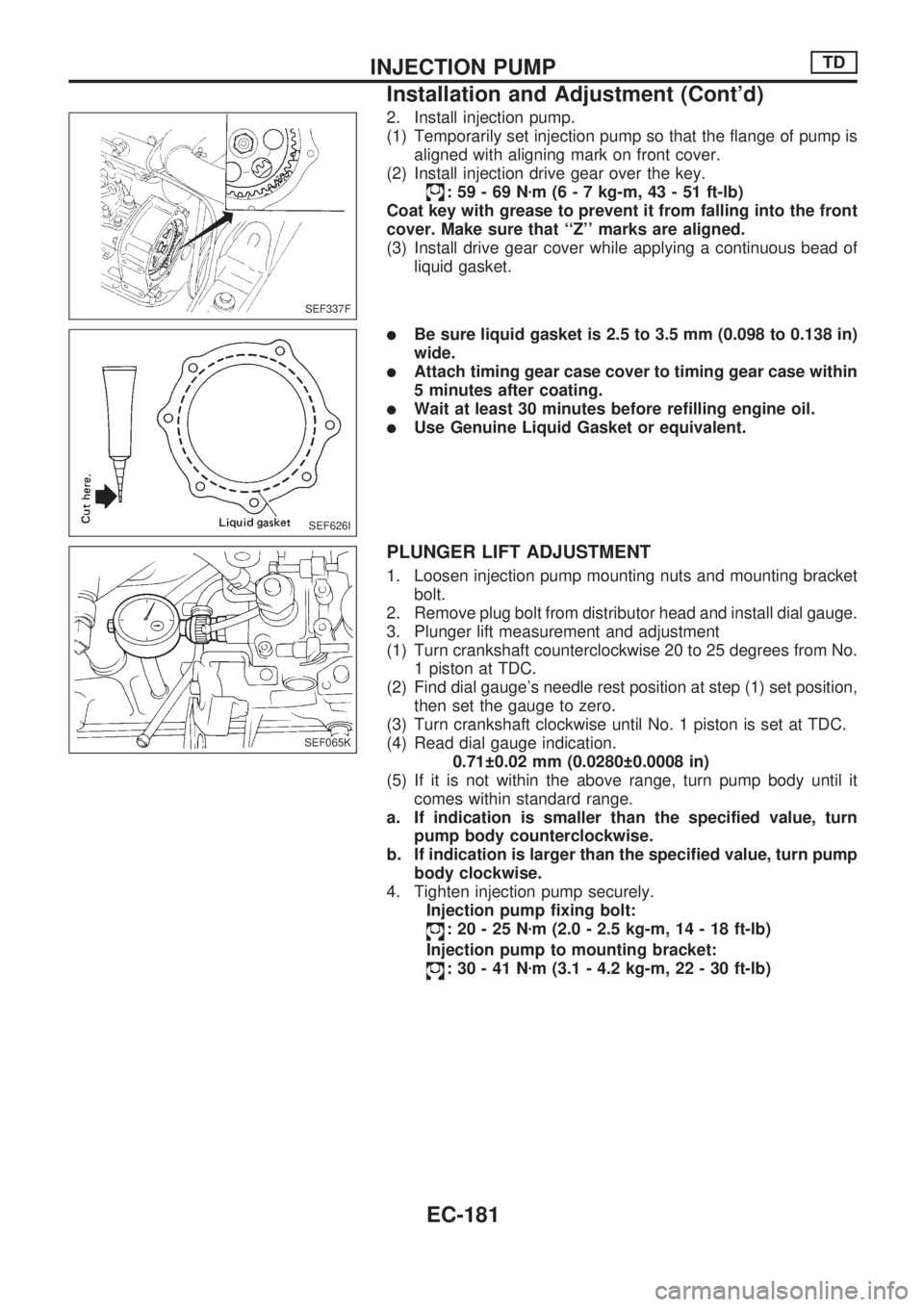
2. Install injection pump.
(1) Temporarily set injection pump so that the flange of pump is
aligned with aligning mark on front cover.
(2) Install injection drive gear over the key.
:59-69Nzm (6 - 7 kg-m, 43 - 51 ft-lb)
Coat key with grease to prevent it from falling into the front
cover. Make sure that ``Z'' marks are aligned.
(3) Install drive gear cover while applying a continuous bead of
liquid gasket.
lBe sure liquid gasket is 2.5 to 3.5 mm (0.098 to 0.138 in)
wide.
lAttach timing gear case cover to timing gear case within
5 minutes after coating.
lWait at least 30 minutes before refilling engine oil.
lUse Genuine Liquid Gasket or equivalent.
PLUNGER LIFT ADJUSTMENT
1. Loosen injection pump mounting nuts and mounting bracket
bolt.
2. Remove plug bolt from distributor head and install dial gauge.
3. Plunger lift measurement and adjustment
(1) Turn crankshaft counterclockwise 20 to 25 degrees from No.
1 piston at TDC.
(2) Find dial gauge's needle rest position at step (1) set position,
then set the gauge to zero.
(3) Turn crankshaft clockwise until No. 1 piston is set at TDC.
(4) Read dial gauge indication.
0.71 0.02 mm (0.0280 0.0008 in)
(5) If it is not within the above range, turn pump body until it
comes within standard range.
a. If indication is smaller than the specified value, turn
pump body counterclockwise.
b. If indication is larger than the specified value, turn pump
body clockwise.
4. Tighten injection pump securely.
Injection pump fixing bolt:
:20-25Nzm (2.0 - 2.5 kg-m, 14 - 18 ft-lb)
Injection pump to mounting bracket:
:30-41Nzm (3.1 - 4.2 kg-m, 22 - 30 ft-lb)
SEF337F
SEF626I
SEF065K
INJECTION PUMPTD
Installation and Adjustment (Cont'd)
EC-181
Page 334 of 1659
5. Disconnect dial gauge and reinstall plug bolt with new
washer.
:14-20Nzm (1.4 - 2.0 kg-m, 10 - 14 ft-lb)
6. Connect injection tubes.
Flare nut:
:20-25Nzm (2.0 - 2.5 kg-m, 14 - 18 ft-lb)
7. Bleed air from fuel system.
Refer to EC-191.
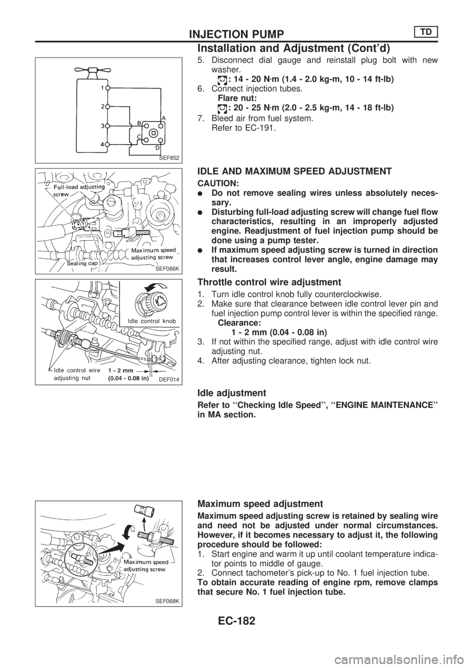
IDLE AND MAXIMUM SPEED ADJUSTMENT
CAUTION:
lDo not remove sealing wires unless absolutely neces-
sary.
lDisturbing full-load adjusting screw will change fuel flow
characteristics, resulting in an improperly adjusted
engine. Readjustment of fuel injection pump should be
done using a pump tester.
lIf maximum speed adjusting screw is turned in direction
that increases control lever angle, engine damage may
result.
Throttle control wire adjustment
1. Turn idle control knob fully counterclockwise.
2. Make sure that clearance between idle control lever pin and
fuel injection pump control lever is within the specified range.
Clearance:
1-2mm(0.04 - 0.08 in)
3. If not within the specified range, adjust with idle control wire
adjusting nut.
4. After adjusting clearance, tighten lock nut.
Idle adjustment
Refer to ``Checking Idle Speed'', ``ENGINE MAINTENANCE''
in MA section.
Maximum speed adjustment
Maximum speed adjusting screw is retained by sealing wire
and need not be adjusted under normal circumstances.
However, if it becomes necessary to adjust it, the following
procedure should be followed:
1. Start engine and warm it up until coolant temperature indica-
tor points to middle of gauge.
2. Connect tachometer's pick-up to No. 1 fuel injection tube.
To obtain accurate reading of engine rpm, remove clamps
that secure No. 1 fuel injection tube.
SEF852
SEF066K
DEF014
SEF068K
INJECTION PUMPTD
Installation and Adjustment (Cont'd)
EC-182
Page 335 of 1659
3. Depress accelerator pedal fully under no load and, at this
point, read the tachometer indication.
Maximum engine speed (Under no load):
5,000
+100
-200rpm
4. If indication is lower than specified maximum engine speed,
turn maximum speed adjusting screw counterclockwise 1 or
2 rotations. Then depress accelerator pedal to floor under no
load and, at this point, read indication.
5. If indication is still lower than specified speed, repeat step 4
above until specified engine speed is reached.
6. After adjustment, tighten lock nut securely.
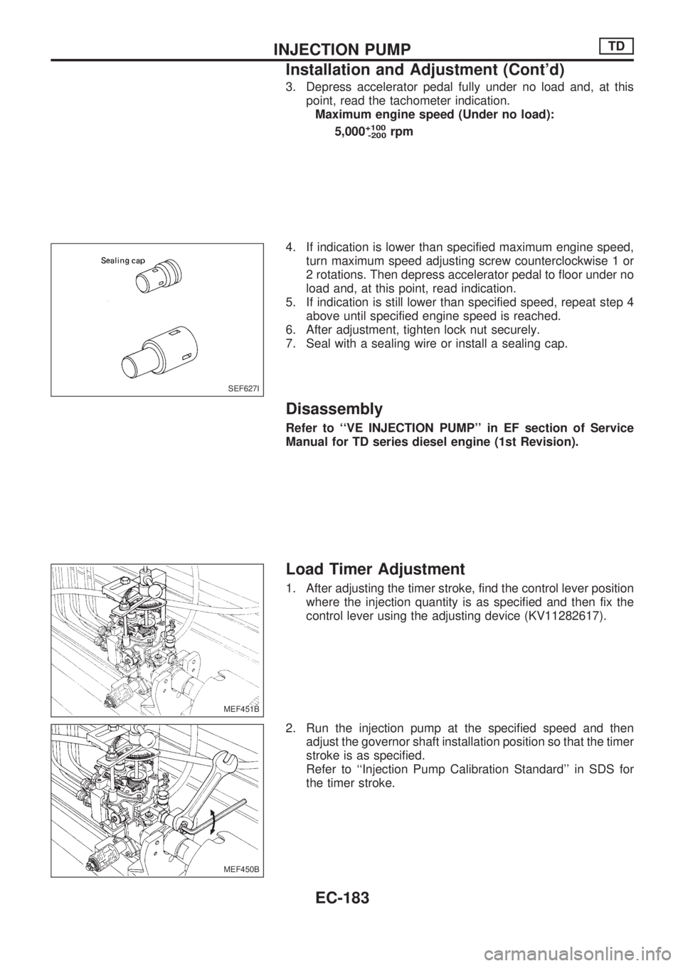
7. Seal with a sealing wire or install a sealing cap.
Disassembly
Refer to ``VE INJECTION PUMP'' in EF section of Service
Manual for TD series diesel engine (1st Revision).
Load Timer Adjustment
1. After adjusting the timer stroke, find the control lever position
where the injection quantity is as specified and then fix the
control lever using the adjusting device (KV11282617).
2. Run the injection pump at the specified speed and then
adjust the governor shaft installation position so that the timer
stroke is as specified.
Refer to ``Injection Pump Calibration Standard'' in SDS for
the timer stroke.
SEF627I
MEF451B
MEF450B
INJECTION PUMPTD
Installation and Adjustment (Cont'd)
EC-183
Page 343 of 1659
Bleeding Fuel System
Air should be bled out of fuel system when injection pump
is removed or fuel system is repaired.
Protect pump and engine mounts from fuel splash with rags.
If engine will not start after bleeding air, loosen injection
tubes at nozzle side and crank engine until fuel overflows
from injection tube. Tighten injection tube flare nuts.
If the engine does not operate smoothly after it has started, race
it two or three times.
CAUTION:
Wipe up any fuel discharged while bleeding air during each
step.
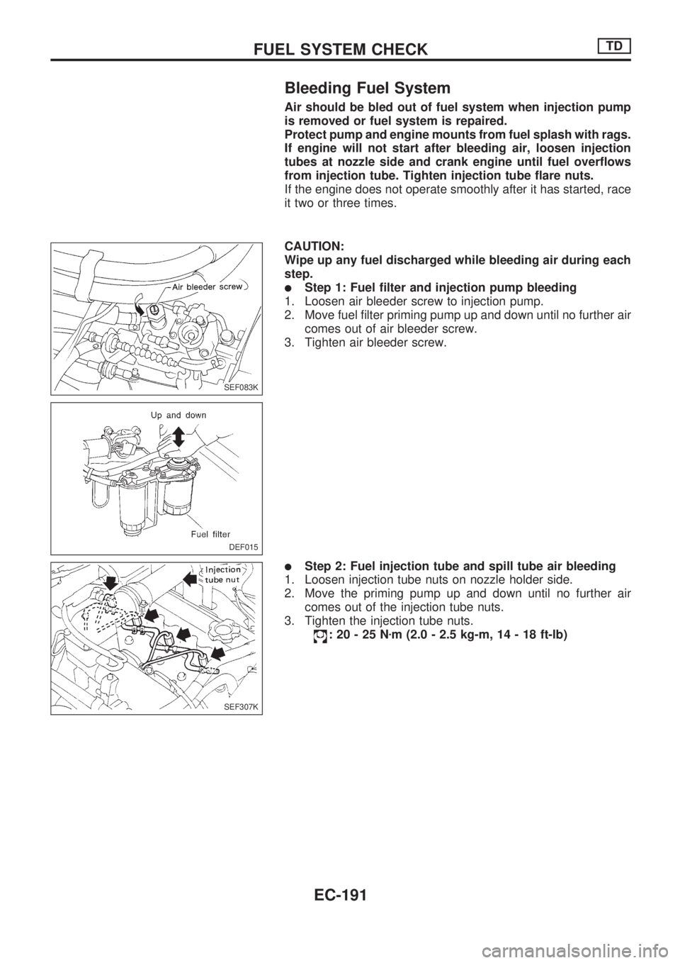
lStep 1: Fuel filter and injection pump bleeding
1. Loosen air bleeder screw to injection pump.
2. Move fuel filter priming pump up and down until no further air
comes out of air bleeder screw.
3. Tighten air bleeder screw.
lStep 2: Fuel injection tube and spill tube air bleeding
1. Loosen injection tube nuts on nozzle holder side.
2. Move the priming pump up and down until no further air
comes out of the injection tube nuts.
3. Tighten the injection tube nuts.
:20-25Nzm (2.0 - 2.5 kg-m, 14 - 18 ft-lb)
SEF083K
DEF015
SEF307K
FUEL SYSTEM CHECKTD
EC-191