Page 279 of 1659
Heated Oxygen Sensor Heater
Ð LHD Models Ð
SYSTEM DESCRIPTION
Camshaft position sensorcEngine speedECM
(ECCS
control
mod-
ule)c
Heated
oxygen
sensor
heater
The ECM performs ON/OFF control of the heated
oxygen sensor heater corresponding to the engine
speed.OPERATION
Engine speed rpm Heated oxygen sensor heater
Above 3,200 OFF
Below 3,200 ON
ECM TERMINALS AND REFERENCE VALUE
Remarks: Specification data are reference values, and are measured between each terminal andV39(ECCS ground) with a voltme-
ter.
TER-
MINAL
NO.WIRE
COLORITEM CONDITIONDATA
(DC voltage)
114 RHeated oxygen sensor
heaterEngine is running.
Engine speed is below 3,200 rpm.Approximately 0V
Engine is running.
Engine speed is above 3,200 rpm.BATTERY VOLTAGE
(11 - 14V)
TROUBLE DIAGNOSIS FOR NON-DETECTABLE ITEMSKA
EC-127
Page 281 of 1659
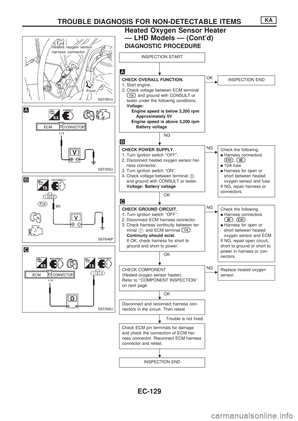
DIAGNOSTIC PROCEDURE
INSPECTION START
CHECK OVERALL FUNCTION.
1. Start engine.
2. Check voltage between ECM terminal
114and ground with CONSULT or
tester under the following conditions.
Voltage:
Engine speed is below 3,200 rpm
Approximately 0V
Engine speed is above 3,200 rpm
Battery voltage
NG
cOK
INSPECTION END
CHECK POWER SUPPLY.
1. Turn ignition switch ``OFF''.
2. Disconnect heated oxygen sensor har-
ness connector.
3. Turn ignition switch ``ON''.
4. Check voltage between terminal
V3
and ground with CONSULT or tester.
Voltage: Battery voltage
OK
cNG
Check the following.
lHarness connectorsE101,M5
l10A fuse
lHarness for open or
short between heated
oxygen sensor and fuse
If NG, repair harness or
connectors.
CHECK GROUND CIRCUIT.
1. Turn ignition switch ``OFF''.
2. Disconnect ECM harness connector.
3. Check harness continuity between ter-
minal
V1and ECM terminal114.
Continuity should exist.
If OK, check harness for short to
ground and short to power.
OK
cNG
Check the following.
lHarness connectorsM5,E101
lHarness for open or
short between heated
oxygen sensor and ECM
If NG, repair open circuit,
short to ground or short to
power in harness or con-
nectors.
CHECK COMPONENT
(Heated oxygen sensor heater).
Refer to ``COMPONENT INSPECTION''
on next page.
OK
cNG
Replace heated oxygen
sensor.
Disconnect and reconnect harness con-
nectors in the circuit. Then retest.
Trouble is not fixed.
Check ECM pin terminals for damage
and check the connection of ECM har-
ness connector. Reconnect ECM harness
connector and retest.
INSPECTION END
SEF091U
SEF093U
SEF646P
SEF094U
.
.
.
.
.
.
.
TROUBLE DIAGNOSIS FOR NON-DETECTABLE ITEMSKA
Heated Oxygen Sensor Heater
Ð LHD Models Ð (Cont'd)
EC-129
Page 283 of 1659
Idle Air Control Valve (IACV) Ð Auxiliary Air
Control (AAC) Valve
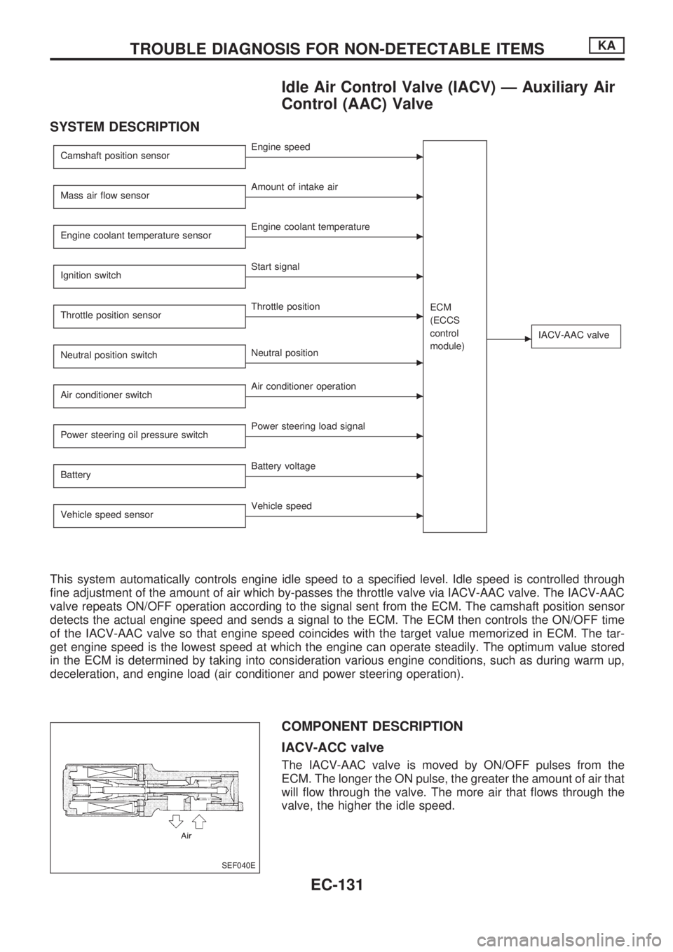
SYSTEM DESCRIPTION
Camshaft position sensorcEngine speed
ECM
(ECCS
control
module)
cIACV-AAC valve
Mass air flow sensorcAmount of intake air
Engine coolant temperature sensor
cEngine coolant temperature
Ignition switch
cStart signal
Throttle position sensor
cThrottle position
Neutral position switch
cNeutral position
Air conditioner switch
cAir conditioner operation
Power steering oil pressure switch
cPower steering load signal
Battery
cBattery voltage
Vehicle speed sensor
cVehicle speed
This system automatically controls engine idle speed to a specified level. Idle speed is controlled through
fine adjustment of the amount of air which by-passes the throttle valve via IACV-AAC valve. The IACV-AAC
valve repeats ON/OFF operation according to the signal sent from the ECM. The camshaft position sensor
detects the actual engine speed and sends a signal to the ECM. The ECM then controls the ON/OFF time
of the IACV-AAC valve so that engine speed coincides with the target value memorized in ECM. The tar-
get engine speed is the lowest speed at which the engine can operate steadily. The optimum value stored
in the ECM is determined by taking into consideration various engine conditions, such as during warm up,
deceleration, and engine load (air conditioner and power steering operation).
COMPONENT DESCRIPTION
IACV-ACC valve
The IACV-AAC valve is moved by ON/OFF pulses from the
ECM. The longer the ON pulse, the greater the amount of air that
will flow through the valve. The more air that flows through the
valve, the higher the idle speed.
SEF040E
TROUBLE DIAGNOSIS FOR NON-DETECTABLE ITEMSKA
EC-131
Page 284 of 1659
CONSULT REFERENCE VALUE IN DATA MONITOR MODE
Remarks: Specification data are reference values.
MONITOR ITEM CONDITION SPECIFICATION
IACV-AAC/V
lEngine: After warming uplAir conditioner switch: ``OFF''lShift lever: Neutral positionlNo-loadIdle 20 - 40%
2,000 rpm Ð
ECM TERMINALS AND REFERENCE VALUE
Remarks: Specification data are reference values, and are measured between each terminal andV39(ECCS ground) with a voltme-
ter.
TER-
MINAL
NO.WIRE
COLORITEM CONDITIONDATA
(DC voltage)
113 W/G IACV-AAC valveEngine is running.
Idle speed10 - 13V
Engine is running.
Steering wheel is being turned.Air conditioner is operating.Rear window defogger switch is ``ON''.Lighting switch is ``ON''.5 - 10V
TROUBLE DIAGNOSIS FOR NON-DETECTABLE ITEMSKA
Idle Air Control Valve (IACV) Ð Auxiliary Air
Control (AAC) Valve (Cont'd)
EC-132
Page 286 of 1659
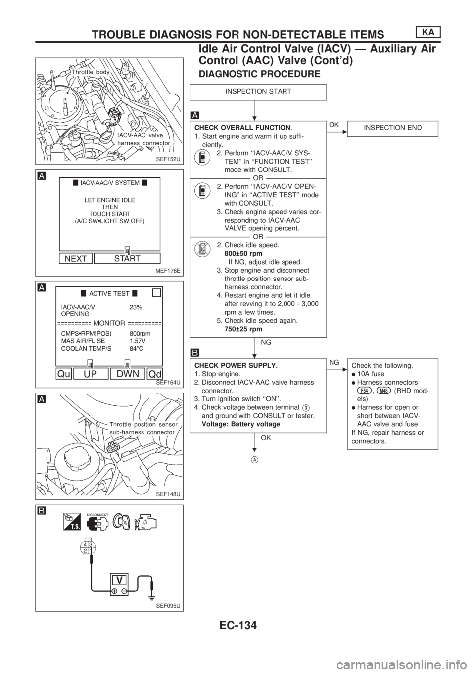
DIAGNOSTIC PROCEDURE
INSPECTION START
CHECK OVERALL FUNCTION.
1. Start engine and warm it up suffi-
ciently.
2. Perform ``IACV-AAC/V SYS-
TEM'' in ``FUNCTION TEST''
mode with CONSULT.
----------------------------------------------------------------------------------------------------------------------------------OR----------------------------------------------------------------------------------------------------------------------------------
2. Perform ``IACV-AAC/V OPEN-
ING'' in ``ACTIVE TEST'' mode
with CONSULT.
3. Check engine speed varies cor-
responding to IACV-AAC
VALVE opening percent.
----------------------------------------------------------------------------------------------------------------------------------OR----------------------------------------------------------------------------------------------------------------------------------
2. Check idle speed.
800 50 rpm
If NG, adjust idle speed.
3. Stop engine and disconnect
throttle position sensor sub-
harness connector.
4. Restart engine and let it idle
after revving it to 2,000 - 3,000
rpm a few times.
5. Check idle speed again.
750 25 rpm
NG
cOK
INSPECTION END
CHECK POWER SUPPLY.
1. Stop engine.
2. Disconnect IACV-AAC valve harness
connector.
3. Turn ignition switch ``ON''.
4. Check voltage between terminal
V3
and ground with CONSULT or tester.
Voltage: Battery voltage
OK
cNG
Check the following.
l10A fuse
lHarness connectorsF54,M48(RHD mod-
els)
lHarness for open or
short between IACV-
AAC valve and fuse
If NG, repair harness or
connectors.
VA
SEF152U
MEF176E
SEF164U
SEF148U
SEF095U
.
.
.
TROUBLE DIAGNOSIS FOR NON-DETECTABLE ITEMSKA
Idle Air Control Valve (IACV) Ð Auxiliary Air
Control (AAC) Valve (Cont'd)
EC-134
Page 292 of 1659
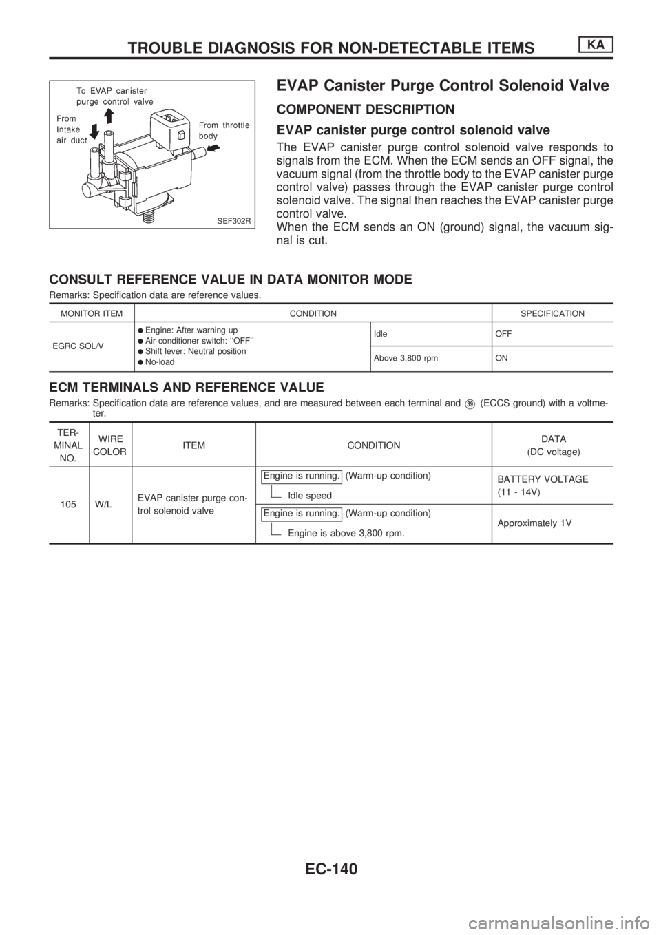
EVAP Canister Purge Control Solenoid Valve
COMPONENT DESCRIPTION
EVAP canister purge control solenoid valve
The EVAP canister purge control solenoid valve responds to
signals from the ECM. When the ECM sends an OFF signal, the
vacuum signal (from the throttle body to the EVAP canister purge
control valve) passes through the EVAP canister purge control
solenoid valve. The signal then reaches the EVAP canister purge
control valve.
When the ECM sends an ON (ground) signal, the vacuum sig-
nal is cut.
CONSULT REFERENCE VALUE IN DATA MONITOR MODE
Remarks: Specification data are reference values.
MONITOR ITEM CONDITION SPECIFICATION
EGRC SOL/V
lEngine: After warning uplAir conditioner switch: ``OFF''lShift lever: Neutral positionlNo-loadIdle OFF
Above 3,800 rpm ON
ECM TERMINALS AND REFERENCE VALUE
Remarks: Specification data are reference values, and are measured between each terminal andV39(ECCS ground) with a voltme-
ter.
TER-
MINAL
NO.WIRE
COLORITEM CONDITIONDATA
(DC voltage)
105 W/LEVAP canister purge con-
trol solenoid valveEngine is running.
(Warm-up condition)
Idle speedBATTERY VOLTAGE
(11 - 14V)
Engine is running.
(Warm-up condition)
Engine is above 3,800 rpm.Approximately 1V
SEF302R
TROUBLE DIAGNOSIS FOR NON-DETECTABLE ITEMSKA
EC-140
Page 294 of 1659
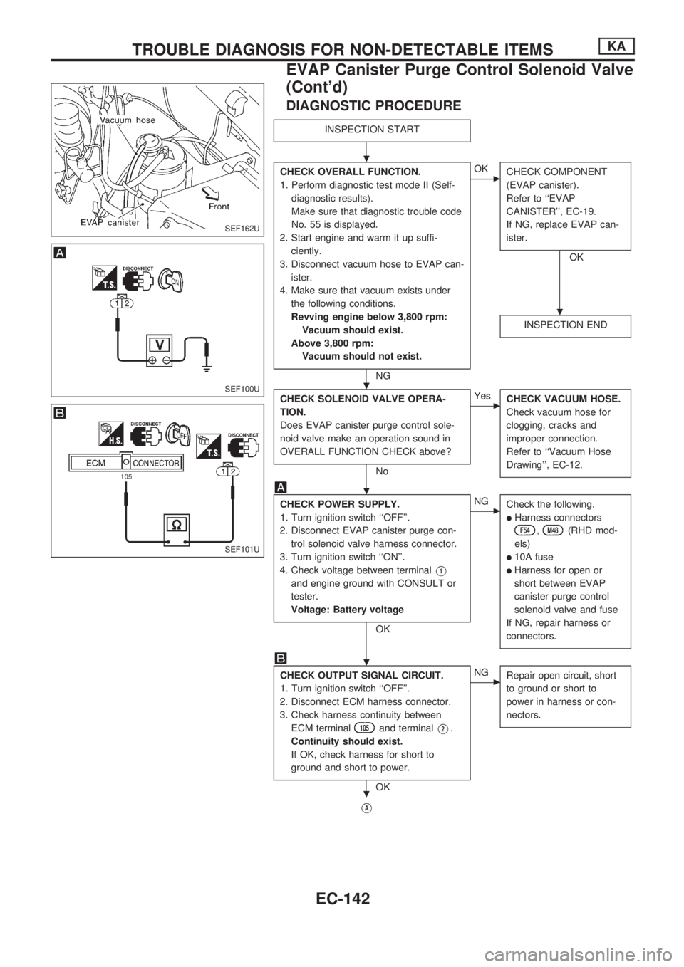
DIAGNOSTIC PROCEDURE
INSPECTION START
CHECK OVERALL FUNCTION.
1. Perform diagnostic test mode II (Self-
diagnostic results).
Make sure that diagnostic trouble code
No. 55 is displayed.
2. Start engine and warm it up suffi-
ciently.
3. Disconnect vacuum hose to EVAP can-
ister.
4. Make sure that vacuum exists under
the following conditions.
Revving engine below 3,800 rpm:
Vacuum should exist.
Above 3,800 rpm:
Vacuum should not exist.
NG
cOK
CHECK COMPONENT
(EVAP canister).
Refer to ``EVAP
CANISTER'', EC-19.
If NG, replace EVAP can-
ister.
OK
INSPECTION END
CHECK SOLENOID VALVE OPERA-
TION.
Does EVAP canister purge control sole-
noid valve make an operation sound in
OVERALL FUNCTION CHECK above?
No
cYes
CHECK VACUUM HOSE.
Check vacuum hose for
clogging, cracks and
improper connection.
Refer to ``Vacuum Hose
Drawing'', EC-12.
CHECK POWER SUPPLY.
1. Turn ignition switch ``OFF''.
2. Disconnect EVAP canister purge con-
trol solenoid valve harness connector.
3. Turn ignition switch ``ON''.
4. Check voltage between terminal
V1
and engine ground with CONSULT or
tester.
Voltage: Battery voltage
OK
cNG
Check the following.
lHarness connectors
F54,M48(RHD mod-
els)
l10A fuse
lHarness for open or
short between EVAP
canister purge control
solenoid valve and fuse
If NG, repair harness or
connectors.
CHECK OUTPUT SIGNAL CIRCUIT.
1. Turn ignition switch ``OFF''.
2. Disconnect ECM harness connector.
3. Check harness continuity between
ECM terminal
105and terminalV2.
Continuity should exist.
If OK, check harness for short to
ground and short to power.
OK
cNG
Repair open circuit, short
to ground or short to
power in harness or con-
nectors.
VA
SEF162U
SEF100U
SEF101U
.
.
.
.
.
.
TROUBLE DIAGNOSIS FOR NON-DETECTABLE ITEMSKA
EVAP Canister Purge Control Solenoid Valve
(Cont'd)
EC-142
Page 298 of 1659
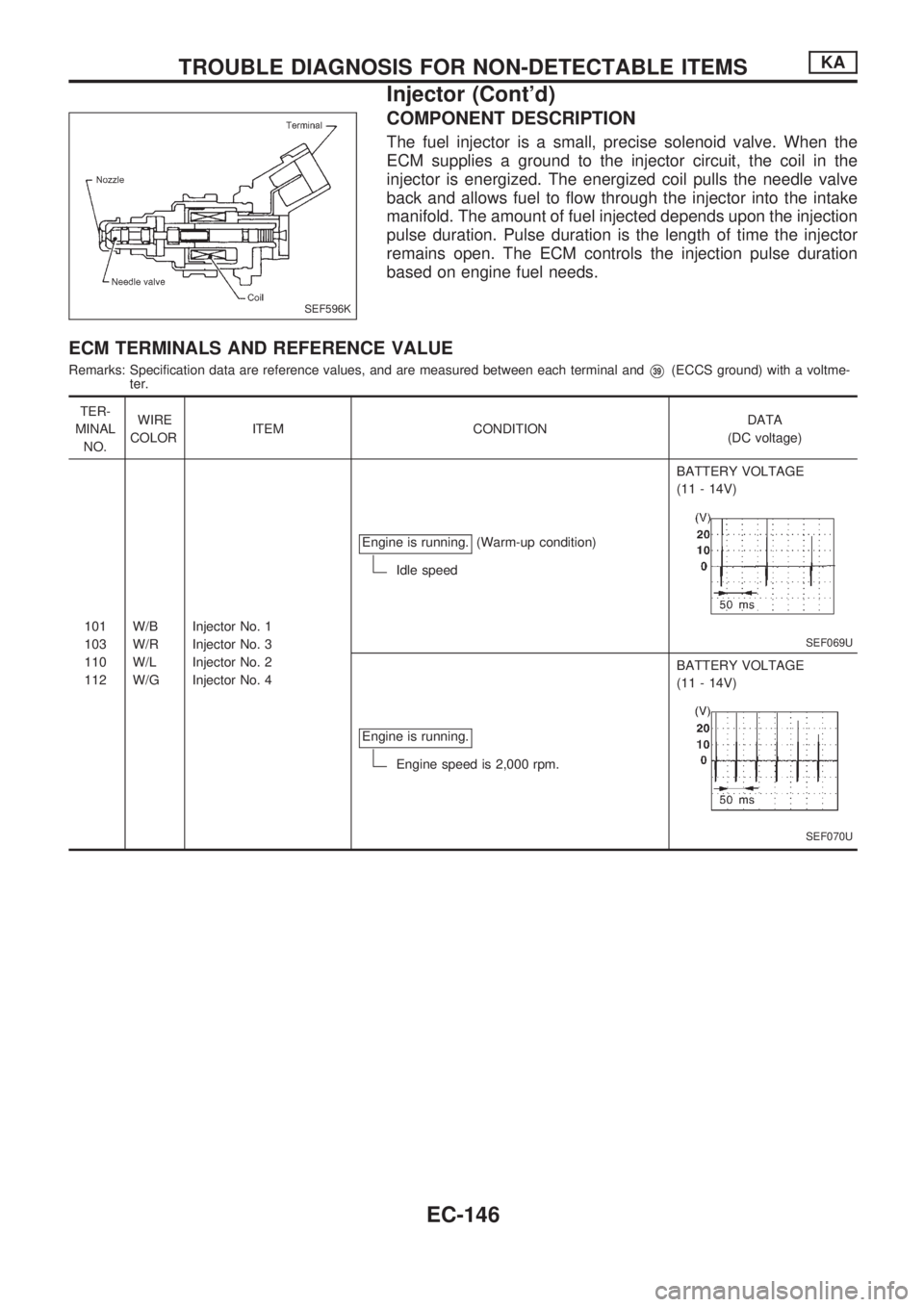
COMPONENT DESCRIPTION
The fuel injector is a small, precise solenoid valve. When the
ECM supplies a ground to the injector circuit, the coil in the
injector is energized. The energized coil pulls the needle valve
back and allows fuel to flow through the injector into the intake
manifold. The amount of fuel injected depends upon the injection
pulse duration. Pulse duration is the length of time the injector
remains open. The ECM controls the injection pulse duration
based on engine fuel needs.
ECM TERMINALS AND REFERENCE VALUE
Remarks: Specification data are reference values, and are measured between each terminal andV39(ECCS ground) with a voltme-
ter.
TER-
MINAL
NO.WIRE
COLORITEM CONDITIONDATA
(DC voltage)
101
103
110
112W/B
W/R
W/L
W/GInjector No. 1
Injector No. 3
Injector No. 2
Injector No. 4Engine is running.
(Warm-up condition)
Idle speedBATTERY VOLTAGE
(11 - 14V)
SEF069U
Engine is running.
Engine speed is 2,000 rpm.BATTERY VOLTAGE
(11 - 14V)
SEF070U
SEF596K
TROUBLE DIAGNOSIS FOR NON-DETECTABLE ITEMSKA
Injector (Cont'd)
EC-146