Page 357 of 1659

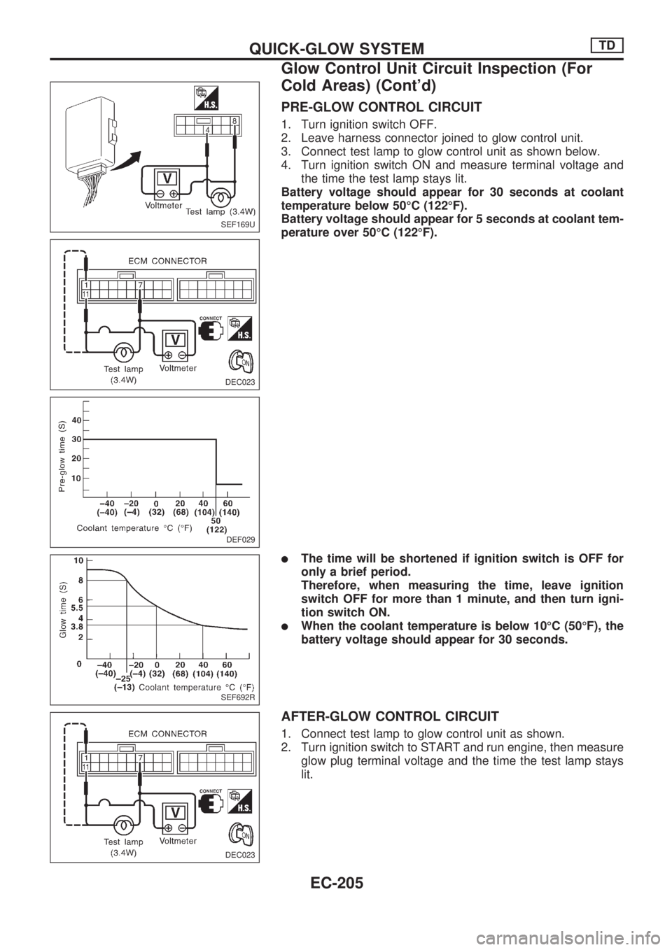
PRE-GLOW CONTROL CIRCUIT
1. Turn ignition switch OFF.
2. Leave harness connector joined to glow control unit.
3. Connect test lamp to glow control unit as shown below.
4. Turn ignition switch ON and measure terminal voltage and
the time the test lamp stays lit.
Battery voltage should appear for 30 seconds at coolant
temperature below 50ÉC (122ÉF).
Battery voltage should appear for 5 seconds at coolant tem-
perature over 50ÉC (122ÉF).
lThe time will be shortened if ignition switch is OFF for
only a brief period.
Therefore, when measuring the time, leave ignition
switch OFF for more than 1 minute, and then turn igni-
tion switch ON.
lWhen the coolant temperature is below 10ÉC (50ÉF), the
battery voltage should appear for 30 seconds.
AFTER-GLOW CONTROL CIRCUIT
1. Connect test lamp to glow control unit as shown.
2. Turn ignition switch to START and run engine, then measure
glow plug terminal voltage and the time the test lamp stays
lit.
SEF169U
DEC023
DEF029
SEF692R
DEC023
QUICK-GLOW SYSTEMTD
Glow Control Unit Circuit Inspection (For
Cold Areas) (Cont'd)
EC-205
Page 358 of 1659

Battery voltage should continue for 10 minutes at coolant
temperature below 50ÉC (122ÉF).
[If vehicle speed is above 20 km/h (12 MPH), glow plug ter-
minal voltage should drop to 0V. If the speed drops below
10 km/h (6 MPH), the battery voltage should appear.]
The voltage should not appear at coolant temperature over
50ÉC (122ÉF).
Glow Control Unit Circuit Inspection (Except
for Cold Areas)
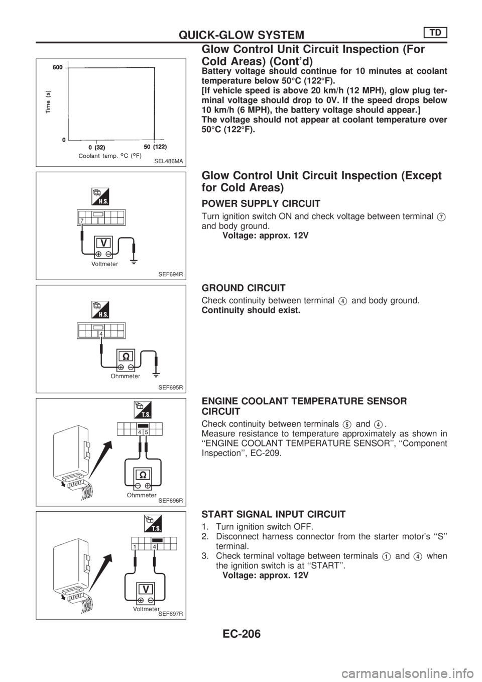
POWER SUPPLY CIRCUIT
Turn ignition switch ON and check voltage between terminalV7
and body ground.
Voltage: approx. 12V
GROUND CIRCUIT
Check continuity between terminalV4and body ground.
Continuity should exist.
ENGINE COOLANT TEMPERATURE SENSOR
CIRCUIT
Check continuity between terminalsV5andV4.
Measure resistance to temperature approximately as shown in
``ENGINE COOLANT TEMPERATURE SENSOR'', ``Component
Inspection'', EC-209.
START SIGNAL INPUT CIRCUIT
1. Turn ignition switch OFF.
2. Disconnect harness connector from the starter motor's ``S''
terminal.
3. Check terminal voltage between terminals
V1andV4when
the ignition switch is at ``START''.
Voltage: approx. 12V
SEL486MA
SEF694R
SEF695R
SEF696R
SEF697R
QUICK-GLOW SYSTEMTD
Glow Control Unit Circuit Inspection (For
Cold Areas) (Cont'd)
EC-206
Page 360 of 1659

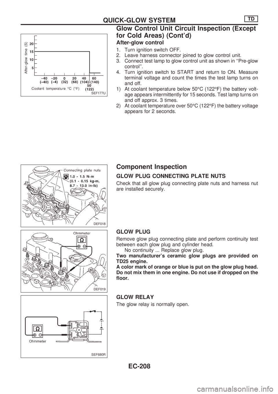
After-glow control
1. Turn ignition switch OFF.
2. Leave harness connector joined to glow control unit.
3. Connect test lamp to glow control unit as shown in ``Pre-glow
control''.
4. Turn ignition switch to START and return to ON. Measure
terminal voltage and count the times the test lamp turns on
and off.
1) At coolant temperature below 50ÉC (122ÉF) the battery volt-
age appears intermittently for 15 seconds. Test lamp turns on
and off approx. 3 times.
2) At coolant temperature over 50ÉC (122ÉF) the battery voltage
appears for 2 seconds.
Component Inspection
GLOW PLUG CONNECTING PLATE NUTS
Check that all glow plug connecting plate nuts and harness nut
are installed securely.
GLOW PLUG
Remove glow plug connecting plate and perform continuity test
between each glow plug and cylinder head.
No continuity ... Replace glow plug.
Two manufacturer's ceramic glow plugs are provided on
TD25 engine.
A color mark of orange or blue is put on the glow plug head.
Do not mix them in one engine. Do not use if dropped on the
floor.
GLOW RELAY
The glow relay is normally open.
SEF177U
DEF018
DEF019
SEF680R
QUICK-GLOW SYSTEMTD
Glow Control Unit Circuit Inspection (Except
for Cold Areas) (Cont'd)
EC-208
Page 361 of 1659
ENGINE COOLANT TEMPERATURE SENSOR
Disconnect engine coolant temperature harness connector and
measure resistance.
Coolant temp. ÉC (ÉF) Resistance kW
þ25 (þ13) 19
0 (32) 5.6
20 (68) 2.5
40 (104) 1.2
DEF020
QUICK-GLOW SYSTEMTD
Component Inspection (Cont'd)
EC-209
Page 364 of 1659
Operation
Coolant
temperature
ÉC (ÉF)Engine load
(EGR area)EGRC-solenoid valve
EGR valveThrottle chamber
control valveAmount of EGR
gas
AB
Below 60 (140) All OFF (Closed) OFF (Closed) Closed Open Ð
Above 60 (140)Low load
(Area
V1)ON (Open) ON (Open) Open Nearly closed High
Middle load
(Area
V2)OFF (Closed) ON (Open) Open Open Low
High load*1
(Area
V3)OFF (Closed) OFF (Closed) Closed Open Ð
*1: Also includes conditions, in which the engine is stopped with the ignition switch ON or the atmospheric pressure is below 90.0
kPa (900 mbar, 675 mmHg, 26.57 inHg).
DEC026
EGR SYSTEMTD
EC-212
Page 365 of 1659
Wiring Diagram
TD25 ENGINE (LHD)
HEC579
EGR SYSTEMTD
EC-213
Page 366 of 1659
TD25 ENGINE (LHD)
HEC580
EGR SYSTEMTD
Wiring Diagram (Cont'd)
EC-214
Page 367 of 1659
TD25 ENGINE (RHD)
HEC581
EGR SYSTEMTD
Wiring Diagram (Cont'd)
EC-215