Page 368 of 1659
TD25 ENGINE (RHD)
HEC582
EGR SYSTEMTD
Wiring Diagram (Cont'd)
EC-216
Page 369 of 1659

System Inspection
OVERALL FUNCTION
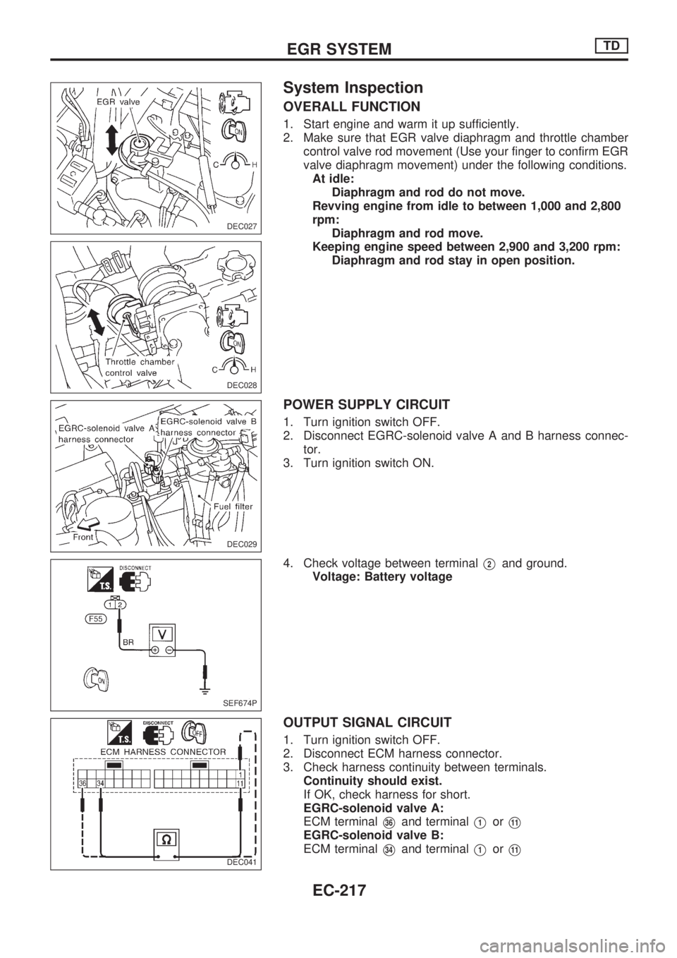
1. Start engine and warm it up sufficiently.
2. Make sure that EGR valve diaphragm and throttle chamber
control valve rod movement (Use your finger to confirm EGR
valve diaphragm movement) under the following conditions.
At idle:
Diaphragm and rod do not move.
Revving engine from idle to between 1,000 and 2,800
rpm:
Diaphragm and rod move.
Keeping engine speed between 2,900 and 3,200 rpm:
Diaphragm and rod stay in open position.
POWER SUPPLY CIRCUIT
1. Turn ignition switch OFF.
2. Disconnect EGRC-solenoid valve A and B harness connec-
tor.
3. Turn ignition switch ON.
4. Check voltage between terminal
V2and ground.
Voltage: Battery voltage
OUTPUT SIGNAL CIRCUIT
1. Turn ignition switch OFF.
2. Disconnect ECM harness connector.
3. Check harness continuity between terminals.
Continuity should exist.
If OK, check harness for short.
EGRC-solenoid valve A:
ECM terminal
V36and terminalV1orV11
EGRC-solenoid valve B:
ECM terminal
V34and terminalV1orV11
DEC027
DEC028
DEC029
SEF674P
DEC041
EGR SYSTEMTD
EC-217
Page 370 of 1659

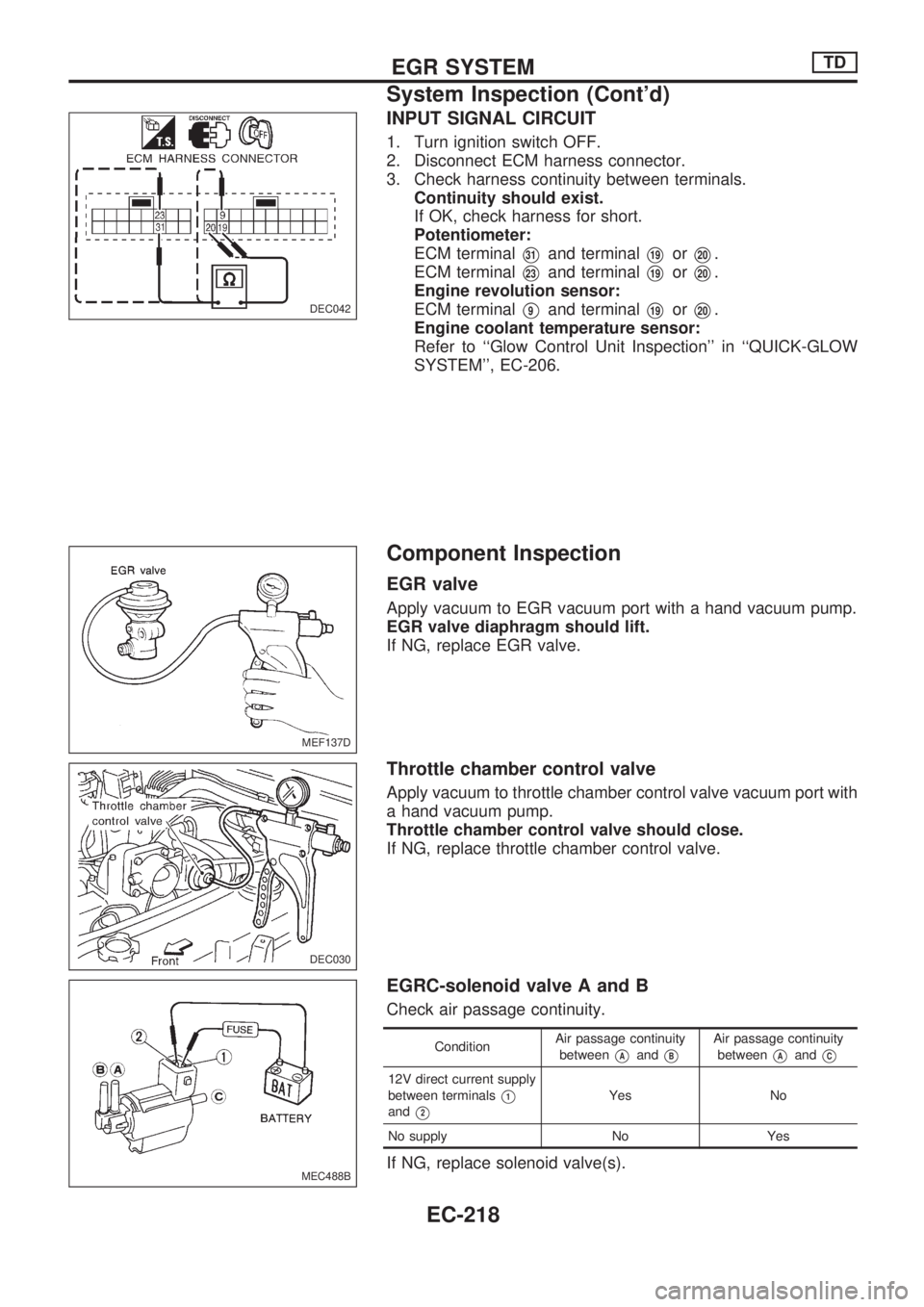
INPUT SIGNAL CIRCUIT
1. Turn ignition switch OFF.
2. Disconnect ECM harness connector.
3. Check harness continuity between terminals.
Continuity should exist.
If OK, check harness for short.
Potentiometer:
ECM terminal
V31and terminalV19orV20.
ECM terminal
V23and terminalV19orV20.
Engine revolution sensor:
ECM terminal
V9and terminalV19orV20.
Engine coolant temperature sensor:
Refer to ``Glow Control Unit Inspection'' in ``QUICK-GLOW
SYSTEM'', EC-206.
Component Inspection
EGR valve
Apply vacuum to EGR vacuum port with a hand vacuum pump.
EGR valve diaphragm should lift.
If NG, replace EGR valve.
Throttle chamber control valve
Apply vacuum to throttle chamber control valve vacuum port with
a hand vacuum pump.
Throttle chamber control valve should close.
If NG, replace throttle chamber control valve.
EGRC-solenoid valve A and B
Check air passage continuity.
ConditionAir passage continuity
betweenVAandVB
Air passage continuity
between
VAandVC
12V direct current supply
between terminals
V1
andV2
Yes No
No supply No Yes
If NG, replace solenoid valve(s).
DEC042
MEF137D
DEC030
MEC488B
EGR SYSTEMTD
System Inspection (Cont'd)
EC-218
Page 371 of 1659
Engine revolution sensor
1. Disconnect engine revolution sensor harness connector.
2. Check resistance between terminals
V1andV2.
Resistance: Approximately 1.6 kW[at 25ÉC (77ÉF)]
If NG, replace sensor.
Potentiometer
1. Disconnect potentiometer harness connector.
2. Make sure that resistance between terminals
V2andV3
changes when accelerator operated.
Accelerator pedal condition Resistance kW[at 20ÉC (68ÉF)]
Completely released Approximately 0.7
Partially depressed 0.7 - 5
Completely depressed Approximately 5
If NG, replace potentiometer.
Atmospheric pressure sensor
This sensor is inside ECM and not replaceable.
EGR system should not operate under atmospheric pressure
below 90.0 kPa (900 mbar, 675 mmHg, 26.57 inHg).
Engine coolant temperature sensor
Refer to ``Component Inspection'' in ``QUICK-GLOW SYSTEM'',
EC-209.
DEC031
DEC032
EGR SYSTEMTD
Component Inspection (Cont'd)
EC-219
Page 372 of 1659
Description
To improve startability, a solenoid timer is used on models for
cold areas. Its purpose is to advance fuel injection timing in
relation to coolant temperature for a certain period after starting
the engine.
This timer is controlled by the signal from the glow control unit
(or ECM). The control unit sends a signal to activate the advance
mechanism of the fuel injection pump during cold starting.
Refer to ``Circuit Diagram'', ``QUICK-GLOW SYSTEM'', EC-195.
Operation
Part of the fuel in the return line returns to the fuel injection pump
inlet, when the solenoid timer is OFF. When cold starting, the
solenoid timer comes ON to stop the return of fuel to the inlet.
This increases the fuel pressure in the fuel injection pump so that
fuel injection timing advances. The duration of fuel injection tim-
ing advance varies with changes in coolant temperature.
SEF419FB
SEF914H
SOLENOID TIMERTD
EC-220
Page 373 of 1659

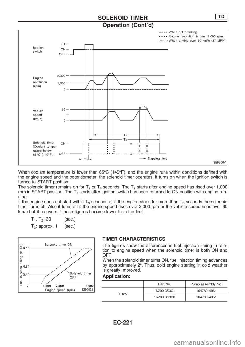
When coolant temperature is lower than 65ÉC (149ÉF), and the engine runs within conditions defined with
the engine speed and the potentiometer, the solenoid timer operates. It turns on when the ignition switch is
turned to START position.
The solenoid timer remains on for T
1or T2seconds. The T1starts after engine speed has rised over 1,000
rpm in START position. The T
2starts after ignition switch has been returned to ON position with engine run-
ning.
If the engine does not start within T
3seconds or if the engine stops for more than T3seconds the solenoid
timer turns off. Also it turns off if the engine speed rises over 2,000 rpm or the vehicle speed rises over 60
km/h but it recovers if these figures become lower than the limit.
T1,T2: 30 [sec.]
T
3: approx. 1 [sec.]
TIMER CHARACTERISTICS
The figures show the differences in fuel injection timing in rela-
tion to engine speed when the solenoid timer is both ON and
OFF.
When the solenoid timer turns ON, fuel injection timing advances
by approximately 2É. Thus, cold engine starting in cold weather
is greatly improved.
Application:
Part No. Pump assembly No.
TD2516700 3S301 104780-4961
16700 3S300 104780-4951
SEF906V
DEC033
.
SOLENOID TIMERTD
Operation (Cont'd)
EC-221
Page 374 of 1659
Wiring Diagram
TD25 ENGINE (LHD)
NOTE: Refer to ``EC-GLOW-03'' for vehicle speed sensor, and ``EC-EGRC/V-02'' for potentiometer.HEC577
.
EC±PLA±01
SOLENOID TIMERTD
EC-222
Page 375 of 1659
TD25 ENGINE (RHD)
NOTE: Refer to ``EC-GLOW-06'' for vehicle speed sensor, and ``EC-EGRC/V-04'' for potentiometer.
HEC578
.
EC±PLA±02
SOLENOID TIMERTD
Wiring Diagram (Cont'd)
EC-223