Page 406 of 1659
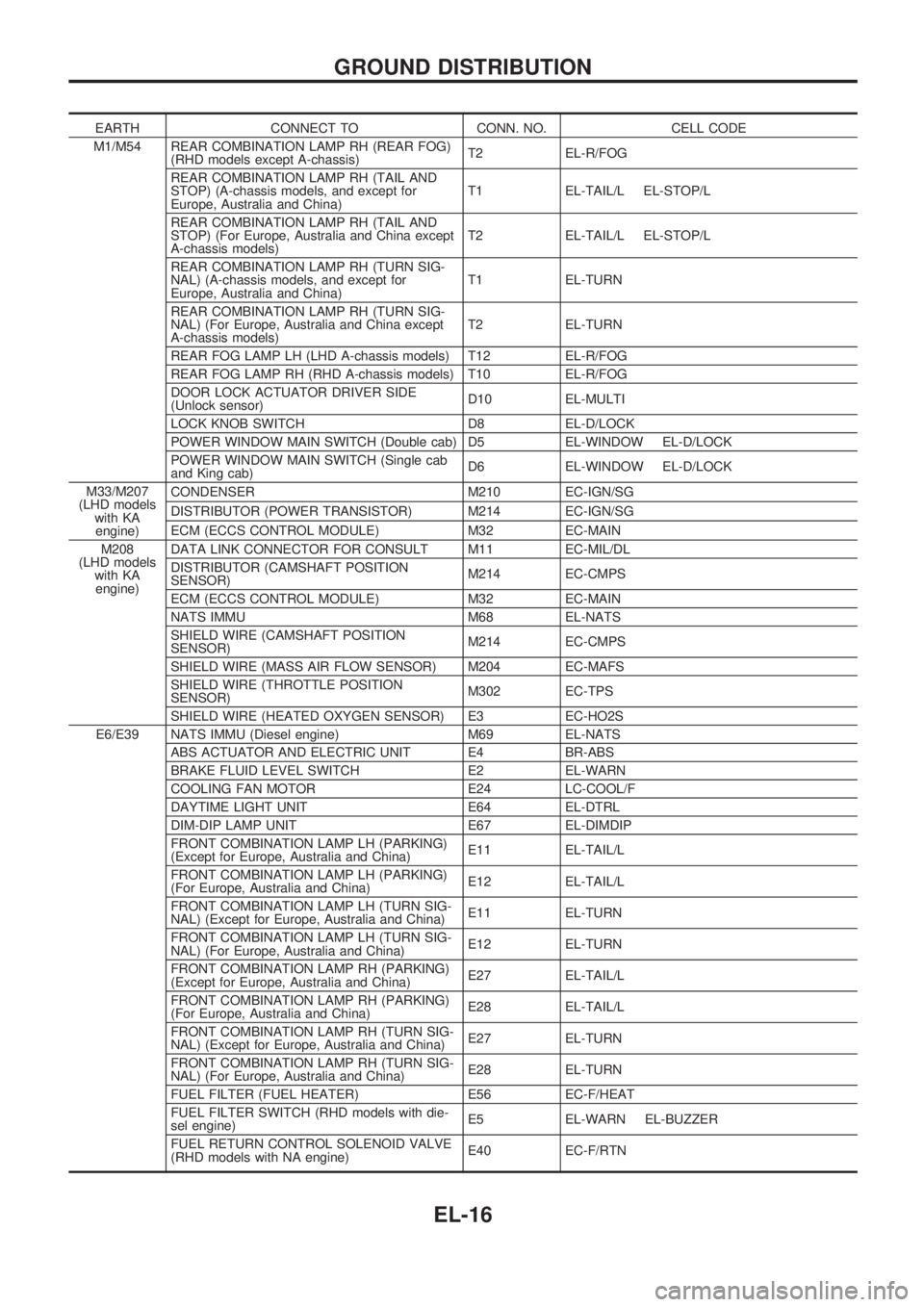
EARTH CONNECT TO CONN. NO. CELL CODE
M1/M54 REAR COMBINATION LAMP RH (REAR FOG)
(RHD models except A-chassis)T2 EL-R/FOG
REAR COMBINATION LAMP RH (TAIL AND
STOP) (A-chassis models, and except for
Europe, Australia and China)T1 EL-TAIL/L EL-STOP/L
REAR COMBINATION LAMP RH (TAIL AND
STOP) (For Europe, Australia and China except
A-chassis models)T2 EL-TAIL/L EL-STOP/L
REAR COMBINATION LAMP RH (TURN SIG-
NAL) (A-chassis models, and except for
Europe, Australia and China)T1 EL-TURN
REAR COMBINATION LAMP RH (TURN SIG-
NAL) (For Europe, Australia and China except
A-chassis models)T2 EL-TURN
REAR FOG LAMP LH (LHD A-chassis models) T12 EL-R/FOG
REAR FOG LAMP RH (RHD A-chassis models) T10 EL-R/FOG
DOOR LOCK ACTUATOR DRIVER SIDE
(Unlock sensor)D10 EL-MULTI
LOCK KNOB SWITCH D8 EL-D/LOCK
POWER WINDOW MAIN SWITCH (Double cab) D5 EL-WINDOW EL-D/LOCK
POWER WINDOW MAIN SWITCH (Single cab
and King cab)D6 EL-WINDOW EL-D/LOCK
M33/M207
(LHD models
with KA
engine)CONDENSER M210 EC-IGN/SG
DISTRIBUTOR (POWER TRANSISTOR) M214 EC-IGN/SG
ECM (ECCS CONTROL MODULE) M32 EC-MAIN
M208
(LHD models
with KA
engine)DATA LINK CONNECTOR FOR CONSULT M11 EC-MIL/DL
DISTRIBUTOR (CAMSHAFT POSITION
SENSOR)M214 EC-CMPS
ECM (ECCS CONTROL MODULE) M32 EC-MAIN
NATS IMMU M68 EL-NATS
SHIELD WIRE (CAMSHAFT POSITION
SENSOR)M214 EC-CMPS
SHIELD WIRE (MASS AIR FLOW SENSOR) M204 EC-MAFS
SHIELD WIRE (THROTTLE POSITION
SENSOR)M302 EC-TPS
SHIELD WIRE (HEATED OXYGEN SENSOR) E3 EC-HO2S
E6/E39 NATS IMMU (Diesel engine) M69 EL-NATS
ABS ACTUATOR AND ELECTRIC UNIT E4 BR-ABS
BRAKE FLUID LEVEL SWITCH E2 EL-WARN
COOLING FAN MOTOR E24 LC-COOL/F
DAYTIME LIGHT UNIT E64 EL-DTRL
DIM-DIP LAMP UNIT E67 EL-DIMDIP
FRONT COMBINATION LAMP LH (PARKING)
(Except for Europe, Australia and China)E11 EL-TAIL/L
FRONT COMBINATION LAMP LH (PARKING)
(For Europe, Australia and China)E12 EL-TAIL/L
FRONT COMBINATION LAMP LH (TURN SIG-
NAL) (Except for Europe, Australia and China)E11 EL-TURN
FRONT COMBINATION LAMP LH (TURN SIG-
NAL) (For Europe, Australia and China)E12 EL-TURN
FRONT COMBINATION LAMP RH (PARKING)
(Except for Europe, Australia and China)E27 EL-TAIL/L
FRONT COMBINATION LAMP RH (PARKING)
(For Europe, Australia and China)E28 EL-TAIL/L
FRONT COMBINATION LAMP RH (TURN SIG-
NAL) (Except for Europe, Australia and China)E27 EL-TURN
FRONT COMBINATION LAMP RH (TURN SIG-
NAL) (For Europe, Australia and China)E28 EL-TURN
FUEL FILTER (FUEL HEATER) E56 EC-F/HEAT
FUEL FILTER SWITCH (RHD models with die-
sel engine)E5 EL-WARN EL-BUZZER
FUEL RETURN CONTROL SOLENOID VALVE
(RHD models with NA engine)E40 EC-F/RTN
GROUND DISTRIBUTION
EL-16
Page 407 of 1659
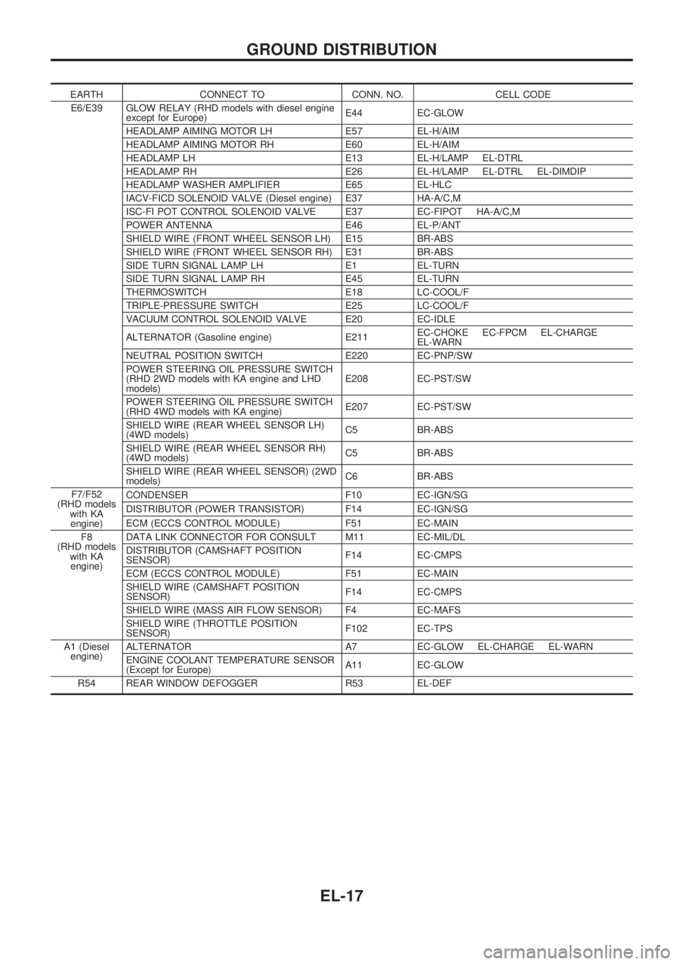
EARTH CONNECT TO CONN. NO. CELL CODE
E6/E39 GLOW RELAY (RHD models with diesel engine
except for Europe)E44 EC-GLOW
HEADLAMP AIMING MOTOR LH E57 EL-H/AIM
HEADLAMP AIMING MOTOR RH E60 EL-H/AIM
HEADLAMP LH E13 EL-H/LAMP EL-DTRL
HEADLAMP RH E26 EL-H/LAMP EL-DTRL EL-DIMDIP
HEADLAMP WASHER AMPLIFIER E65 EL-HLC
IACV-FICD SOLENOID VALVE (Diesel engine) E37 HA-A/C,M
ISC-FI POT CONTROL SOLENOID VALVE E37 EC-FIPOT HA-A/C,M
POWER ANTENNA E46 EL-P/ANT
SHIELD WIRE (FRONT WHEEL SENSOR LH) E15 BR-ABS
SHIELD WIRE (FRONT WHEEL SENSOR RH) E31 BR-ABS
SIDE TURN SIGNAL LAMP LH E1 EL-TURN
SIDE TURN SIGNAL LAMP RH E45 EL-TURN
THERMOSWITCH E18 LC-COOL/F
TRIPLE-PRESSURE SWITCH E25 LC-COOL/F
VACUUM CONTROL SOLENOID VALVE E20 EC-IDLE
ALTERNATOR (Gasoline engine) E211EC-CHOKE EC-FPCM EL-CHARGE
EL-WARN
NEUTRAL POSITION SWITCH E220 EC-PNP/SW
POWER STEERING OIL PRESSURE SWITCH
(RHD 2WD models with KA engine and LHD
models)E208 EC-PST/SW
POWER STEERING OIL PRESSURE SWITCH
(RHD 4WD models with KA engine)E207 EC-PST/SW
SHIELD WIRE (REAR WHEEL SENSOR LH)
(4WD models)C5 BR-ABS
SHIELD WIRE (REAR WHEEL SENSOR RH)
(4WD models)C5 BR-ABS
SHIELD WIRE (REAR WHEEL SENSOR) (2WD
models)C6 BR-ABS
F7/F52
(RHD models
with KA
engine)CONDENSER F10 EC-IGN/SG
DISTRIBUTOR (POWER TRANSISTOR) F14 EC-IGN/SG
ECM (ECCS CONTROL MODULE) F51 EC-MAIN
F8
(RHD models
with KA
engine)DATA LINK CONNECTOR FOR CONSULT M11 EC-MIL/DL
DISTRIBUTOR (CAMSHAFT POSITION
SENSOR)F14 EC-CMPS
ECM (ECCS CONTROL MODULE) F51 EC-MAIN
SHIELD WIRE (CAMSHAFT POSITION
SENSOR)F14 EC-CMPS
SHIELD WIRE (MASS AIR FLOW SENSOR) F4 EC-MAFS
SHIELD WIRE (THROTTLE POSITION
SENSOR)F102 EC-TPS
A1 (Diesel
engine)ALTERNATOR A7 EC-GLOW EL-CHARGE EL-WARN
ENGINE COOLANT TEMPERATURE SENSOR
(Except for Europe)A11 EC-GLOW
R54 REAR WINDOW DEFOGGER R53 EL-DEF
GROUND DISTRIBUTION
EL-17
Page 408 of 1659
CAUTION:
If it becomes necessary to start the engine with a booster
battery and jumper cables,
a. Use a 12-volt booster battery.
b. After connecting battery cables, ensure that they are
tightly clamped to battery terminals for good contact.
c. Never add distilled water through the hole used to check
specific gravity.
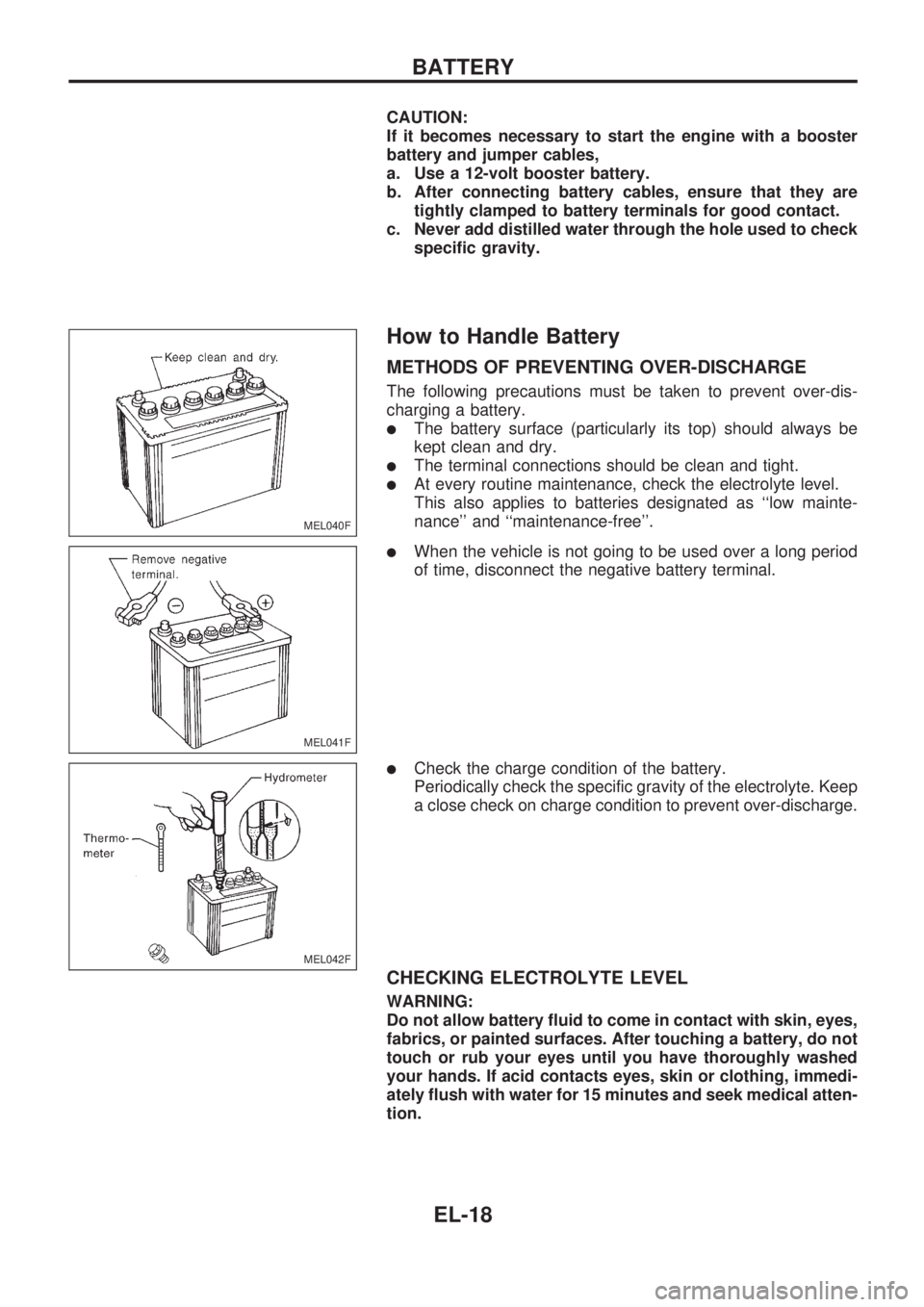
How to Handle Battery
METHODS OF PREVENTING OVER-DISCHARGE
The following precautions must be taken to prevent over-dis-
charging a battery.
lThe battery surface (particularly its top) should always be
kept clean and dry.
lThe terminal connections should be clean and tight.
lAt every routine maintenance, check the electrolyte level.
This also applies to batteries designated as ``low mainte-
nance'' and ``maintenance-free''.
lWhen the vehicle is not going to be used over a long period
of time, disconnect the negative battery terminal.
lCheck the charge condition of the battery.
Periodically check the specific gravity of the electrolyte. Keep
a close check on charge condition to prevent over-discharge.
CHECKING ELECTROLYTE LEVEL
WARNING:
Do not allow battery fluid to come in contact with skin, eyes,
fabrics, or painted surfaces. After touching a battery, do not
touch or rub your eyes until you have thoroughly washed
your hands. If acid contacts eyes, skin or clothing, immedi-
ately flush with water for 15 minutes and seek medical atten-
tion.
MEL040F
MEL041F
MEL042F
BATTERY
EL-18
Page 417 of 1659
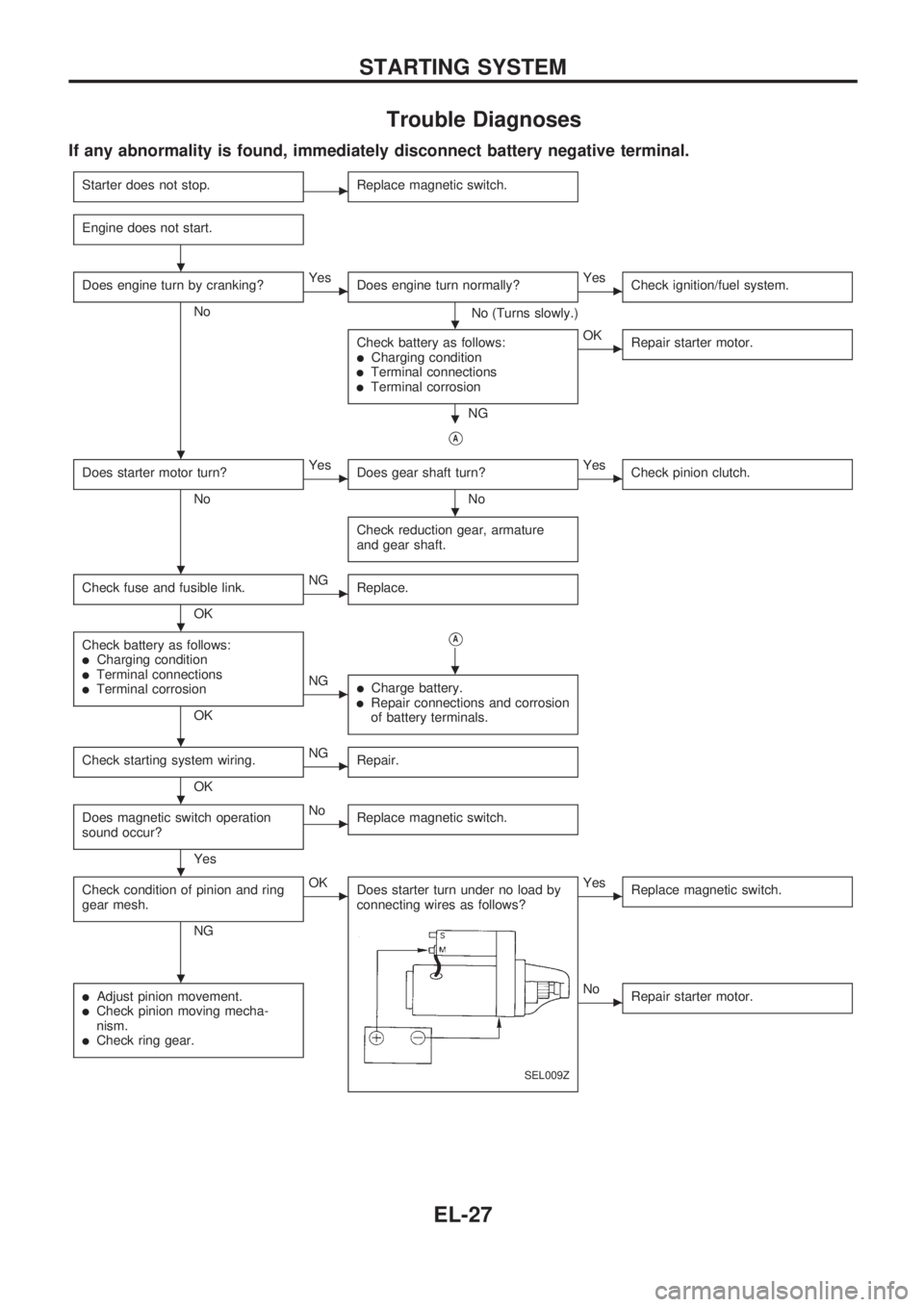
Trouble Diagnoses
If any abnormality is found, immediately disconnect battery negative terminal.
Starter does not stop.cReplace magnetic switch.
Engine does not start.
Does engine turn by cranking?
No
cYes
Does engine turn normally?
No (Turns slowly.)
cYes
Check ignition/fuel system.
Check battery as follows:lCharging conditionlTerminal connectionslTerminal corrosion
NG
cOK
Repair starter motor.
VA
Does starter motor turn?
No
cYes
Does gear shaft turn?
No
cYes
Check pinion clutch.
Check reduction gear, armature
and gear shaft.
Check fuse and fusible link.
OK
cNG
Replace.
Check battery as follows:lCharging conditionlTerminal connectionslTerminal corrosion
OK
VA
cNGlCharge battery.lRepair connections and corrosion
of battery terminals.
Check starting system wiring.
OK
cNG
Repair.
Does magnetic switch operation
sound occur?
Yes
cNo
Replace magnetic switch.
Check condition of pinion and ring
gear mesh.
NG
cOK
Does starter turn under no load by
connecting wires as follows?
SEL009Z
cYes
Replace magnetic switch.
lAdjust pinion movement.lCheck pinion moving mecha-
nism.
lCheck ring gear.
cNo
Repair starter motor.
.
.
.
.
.
.
.
.
.
.
.
.
STARTING SYSTEM
EL-27
Page 424 of 1659
Wiring Diagram Ð CHARGE Ð/Gasoline
Engine
HEL318A
CHARGING SYSTEM
EL-34
Page 425 of 1659
Wiring Diagram Ð CHARGE Ð/Diesel Engine
HEL319A
CHARGING SYSTEM
EL-35
Page 426 of 1659
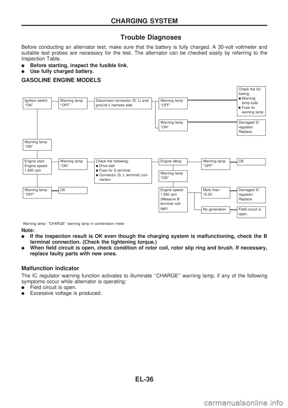
Trouble Diagnoses
Before conducting an alternator test, make sure that the battery is fully charged. A 30-volt voltmeter and
suitable test probes are necessary for the test. The alternator can be checked easily by referring to the
Inspection Table.
lBefore starting, inspect the fusible link.
lUse fully charged battery.
GASOLINE ENGINE MODELS
Check the fol-
lowing:
lWarning
lamp bulb
lFuse for
warning lamp
Ignition switch
``ON''Warning lamp
``OFF''Disconnect connector (S, L) and
ground L harness side.Warning lamp
``OFF''
Warning lamp
``ON''Damaged IC
regulator.
Replace.
Warning lamp
``ON''
Engine start.
Engine speed:
1,500 rpmWarning lamp
``ON''Check the following:lDrive beltlFuse for S terminallConnector (S, L terminal) con-
nection
Engine idlingWarning lamp
``OFF''OK
Warning lamp
``ON''
Warning lamp
``OFF''OKEngine speed:
1,500 rpm
(Measure B
terminal volt-
age)More than
15.5VDamaged IC
regulator.
Replace.
No generationField circuit is
open.
Warning lamp: ``CHARGE'' warning lamp in combination meter
Note:
lIf the inspection result is OK even though the charging system is malfunctioning, check the B
terminal connection. (Check the tightening torque.)
lWhen field circuit is open, check condition of rotor coil, rotor slip ring and brush. If necessary,
replace faulty parts with new ones.
Malfunction indicator
The IC regulator warning function activates to illuminate ``CHARGE'' warning lamp, if any of the following
symptoms occur while alternator is operating:
lField circuit is open.
lExcessive voltage is produced.
CHARGING SYSTEM
EL-36
Page 427 of 1659
DIESEL ENGINE MODELS
Check the fol-
lowing:
lWarning
lamp bulb
lFuse for
warning lamp
Ignition switch
``ON''Warning lamp
``OFF''Disconnect connector (S, L) and
ground L harness side.Warning lamp
``OFF''
Warning lamp
``ON''Damaged IC
regulator.
Replace.
Warning lamp
``ON''
Engine idlingWarning lamp
``ON''Check the fol-
lowing:
lDrive beltlField circuit
Check the fol-
lowing:
lFuse for S
terminal
lOpen circuit
for S terminal
lIC regulator
Warning lamp
``OFF''Engine speed: 1,500 rpm
(Measure B terminal voltage)More than
15.5V
13 - 15VOK
Warning lamp: ``CHARGE'' warning lamp in combination meter
Note:
lIf the inspection result is OK even though the charging system is malfunctioning, check the B
terminal connection (check the tightening torque).
lWhen field circuit is open, check condition of rotor coil, rotor slip ring and brush. If necessary,
replace faulty parts with new ones.
CHARGING SYSTEM
Trouble Diagnoses (Cont'd)
EL-37