1998 JAGUAR X308 Joint
[x] Cancel search: JointPage 1837 of 2490
System Self-test
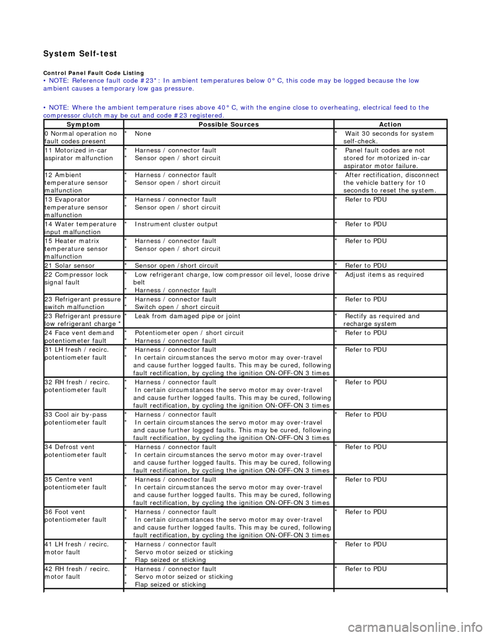
Control Panel Fault Code Listing • NOTE: Reference fault code #23*: In ambient temperatures below 0° C, this code may be logged because the low
ambient causes a tempor ary low gas pressure.
• NOTE: Where the ambient temperature rises above 40° C, with the engine close to overheating, electrical feed to the
compressor clutch may be cut and code #23 registered.
SymptomPossible SourcesAction
0 Normal operation no
fault codes presentNone
*Wait 30 seconds for system
self-check.
*
11 Motorized in-car
aspirator malfunctionHarness / connector fault
Sensor open / short circuit
*
*Panel fault codes are not
stored for motorized in-car
aspirator motor failure.
*
12 Ambient
temperature sensor
malfunctionHarness / connector fault
Sensor open / short circuit
*
*After rectification, disconnect
the vehicle battery for 10
seconds to reset the system.
*
13 Evaporator
temperature sensor
malfunctionHarness / connector fault
Sensor open / short circuit
*
*Refer to PDU
*
14 Water temperature
input malfunctionInstrument cl uster output
*Refer to PDU
*
15 Heater matrix
temperature sensor
malfunctionHarness / connector fault
Sensor open / short circuit
*
*Refer to PDU
*
21 Solar sensorSensor open /short circuit
*Refer to PDU
*
22 Compressor lock
signal faultLow refrigerant charge, low compressor oil level, loose drive
belt Harness / connector fault
*
*Adjust items as required
*
23 Refrigerant pressure
switch malfunctionHarness / connector fault
Switch open / short circuit
*
*Refer to PDU
*
23 Refrigerant pressure
low refrigerant charge * Leak from damaged pipe or joint
*Rectify as required and
recharge system
*
24 Face vent demand
potentiometer faultPotentiometer open / short circuit
Harness / connector fault
*
*Refer to PDU
*
31 LH fresh / recirc.
potentiometer faultHarness / connector fault
In certain circumstances the servo motor may over-travel
and cause further logged faults. This may be cured, following
fault rectification, by cycling the ignition ON-OFF-ON 3 times
*
*Refer to PDU
*
32 RH fresh / recirc.
potentiometer faultHarness / connector fault
In certain circumstances the servo motor may over-travel
and cause further logged faults. This may be cured, following
fault rectification, by cycling the ignition ON-OFF-ON 3 times
*
*Refer to PDU
*
33 Cool air by-pass
potentiometer faultHarness / connector fault
In certain circumstances the servo motor may over-travel
and cause further logged faults. This may be cured, following
fault rectification, by cycling the ignition ON-OFF-ON 3 times
*
*Refer to PDU
*
34 Defrost vent
potentiometer faultHarness / connector fault
In certain circumstances the servo motor may over-travel
and cause further logged faults. This may be cured, following
fault rectification, by cycling the ignition ON-OFF-ON 3 times
*
*Refer to PDU
*
35 Centre vent
potentiometer faultHarness / connector fault
In certain circumstances the servo motor may over-travel
and cause further logged faults. This may be cured, following
fault rectification, by cycling the ignition ON-OFF-ON 3 times
*
*Refer to PDU
*
36 Foot vent
potentiometer faultHarness / connector fault
In certain circumstances the servo motor may over-travel
and cause further logged faults. This may be cured, following
fault rectification, by cycling the ignition ON-OFF-ON 3 times
*
*Refer to PDU
*
41 LH fresh / recirc.
motor faultHarness / connector fault
Servo motor seized or sticking
Flap seized or sticking
*
*
*Refer to PDU
*
42 RH fresh / recirc.
motor faultHarness / connector fault
Servo motor seized or sticking
Flap seized or sticking
*
*
*Refer to PDU
*
Page 1989 of 2490

Wiring Harnesses - Wiring Harness
Description and Operation
Introduction
CAUTION: Do not use any other heat shrink sleeve other than the approved glue lined heat shrink sleeve mentioned
in the repair procedure.
The purpose of this document is to promote quick and efficient minor repair to harness connectors or cables using approved
methods and the wiring harness repair kit. Repairs may only be made to cables and connectors which have been
mechanically, not electrically damaged. It also applies wher e the whole extent of the damage can be clearly identified and
rectified.
Care and neatness are essential requir ements in making a perfect repair.
Caution:
At the time of this first issue of the Harness Repair Guide, do not approve re pairs to any of the following circuits:
Any media orientated system transport network harnesses. Supplement restraint system (SRS) firing circuits (Air bags). Link lead assembles, which are unique to safety critical circuits such as anti-lock brake system (ABS) and
thermocouple circuits. An example of this is the ABS wheel speed sensors with moulded connectors.
4. Screened cables, leads and wiring harness(s).
If any harness(s) with defective electrical connector te rminals or wires from the above circuits are a concern,
new components must be installed.
Repair Kit
CAUTION: Where the repair procedure indica tes that a glue lined heat shrink sleeve should be applied, apply sufficient
heat to the glue lined heat shrink to melt the glue in order to provide a water tight seal. Do not over heat the glue lined
heat shrink sleeve so that the wiring harness insulation becomes damaged.
The wiring harness repair kit has been produced which comprises:
Pre-terminated wiring harness(s) of different sizes and types Three sizes of butt splice connectors A selection of colored cable identification sleeves Two sizes of glue lined heat shrink sleeves Crimping pliers A wire cutter and insulation stripper An electrical connector terminal extraction handle and tips
A suitable heat source, fo r shrinking heat shrink sleeves will be required.
The pre-insulated diamond grip range of el ectrical connector terminals and in-line, butt splice connectors contained within
the wiring harness repair kit are the only acceptable product for the repairs of wi ring harnesses. The butt connectors not
only grip the wire but also the insu lation, making a very secure joint.
If an electrical connector terminal is not included in the wiring harness repair kit then approval for the repair is NOT given
and in these circumstances a new wi ring harness must be installed.
Pre-Terminated Wiring Harness( s) and Butt Splice Connectors
All pre-terminated wiring harness(s) and butt splice connectors in the wiring harness repair kit are contained in bags which
can be resealed after use. Each bag is marked with the part number of the items stored within the bag. Each storage
compartment in the wiring harness repair kit is identified with the corresponding part number. Make sure that pre-
terminated wiring harness(s) and connectors are not mixed up it is advisable to only open one bag at a time and to reseal
Page 2002 of 2490
Repair Procedure
• CAUTIONS: Do not use crimping pliers, insulation strippers, butt splice connectors, heat sh rink sleeves or pre-terminated wiring
harness(s) that are not supplied with the Jagu ar wiring harness repair kit. Each part has been designed to be used only with
the other parts in this wiri ng harness repair kit.
Where the repair procedure indicates that a glue lined heat shrink sleeve should be applied, apply sufficient heat to
the glue lined heat shrink to melt the glue in order to provide a water tight seal. Do not
over heat the glue lined heat shrink sleeve so that the wiring harness insulation becomes damaged.
It is not correct to make more than five repair joints on the wiring harness to any electrical connector and if more damage is
found at the same electrical connector then a new wiring harness must be installed.
Remove the faulty terminal from the elec trical connector using the extractor tool and correct tip. Make sure that any
anti-backout device is released befo re trying to remove the terminal.
CAUTION: : A number of electrical connector terminals ar e gold plated or gold flashed. When defective, they
must be installed with a gold pre-terminated wiring harnes s(s) from the wiring harness repair kit. It is not always
easy to identify the female as gold but the male pins are visually easier, therefore always check both male and
female terminals to identify those which are gold. Under no circumstances are gold and tin terminals to be mixed as
this will lead to early failur e of the electrical contact.
• NOTE: Never use a harness lead with a smalle r diameter than the original harness lead.
Select the correct size and ty pe of pre-terminated wiring harness and butt splice connector from the wiring harness
repair kit.
Using the wire cutter on the stripping tool, cut the pre-terminated wiring harness and the harness cable to the
required length.
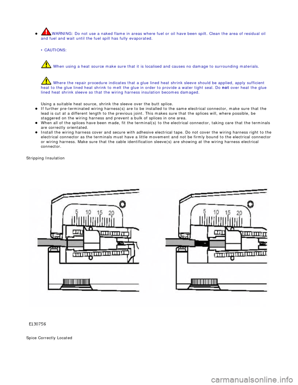
• NOTE: See illustration: Stripping Insulation
From the Relationship Table, find the correct length of insulation to be stripped from the pre-terminated wiring
harness and set the adjustable cable length stop to the correct length. Place the pre-terminated wiring harness in
the wire stripper and remove the insulation.
Put the cable identification sleeve(s) on to the wiring harness with the main cable colour nearest to the terminal. During this next step do not overtighten. Place the selected butt splice connector in the crimping tool, matching the
aperture and the butt connector colours. Make sure that the window indentation in the butt connector is resting over
the guide bar on the lower jaw. Partially close the grip until the butt connec tor is securely held in the aperture. This
will give support to the butt conn ector while the pre-terminated wiring harness is inserted into it.
• NOTE: See illustration: Spice Correctly Located
Insert the pre-terminated wiring harnes s into the butt connector and make sure that the wire is against the wire
stop. Close the grip firmly, crimping the lead to the butt connector. When the handles have been completely closed
the butt connector will be fre ed from the tool as the handles are released. If the handles have not been completely
closed then the jaws will hold the butt connector and it cannot be removed from the tool until the crimp is fully made
by closing the handles completely. Make sure that the harness cable has been squarely cut and the correct length of insulation removed. If more than
one splice is needed the butt connectors must be not be crimped to the wiring harness at the same distance from
the connector. The splices must be staggered to prevent a bulk of splices in the same area of the wiring harness.
It is preferable to cover the butt splice joint with heat shrink sleeve. This is desirable not essential, except where the
electrical connector is a sealed electrical connector. Use the smaller diameter sleeve for red and blue pre-terminated
wiring harness(s) and the large diameter sleeve for the yellow pre-terminated wiring harnes s(s). It is advisable to
place the heat shrink over the completed joint but in some instances the sleeve will not pass over the terminal.
Check, and if required, place the correct size sleeve onto the harness cable or pre-terminated wiring harness before
crimping the butt splice to the wiring harness.
Place the harness cable into the butt splice with the spli ce window over the guide bar. Make sure that the cable
harness wire is agains t the stop in the butt splice, crimp the butt splice connector to the wiring harness.
Gently pull the harness cables each side of the butt sp lice to make sure that a secure joint has been made.
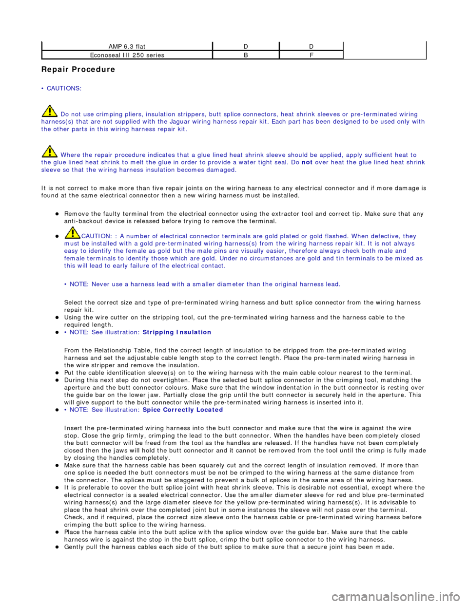
AMP 6.3 flatDD
Econoseal III 250 seriesBF
Page 2003 of 2490
WARNING: Do not use a naked flame in areas where fuel or oil have been spilt. Clean the area of residual oil
and fuel and wait un til the fuel spill has fully evaporated.
• CAUTIONS:
When using a heat source make sure that it is localised and caus es no damage to surrounding materials.
Where the repair procedure indicates that a glue lined heat shrink sleeve should be applied, apply sufficient
heat to the glue lined heat shrink to melt the glue in order to provide a water tight seal. Do not over heat the glue
lined heat shrink sleeve so that the wi ring harness insulation becomes damaged.
Using a suitable heat source, shrink the sleeve over the butt splice.
If further pre-terminated wiri ng harness(s) are to be installed to the sa me electrical connector, make sure that the
lead is cut at a different length to the previous joint. This makes sure that the splices will, where possible, be
staggered on the wiring ha rness and prevent a bulk of splices in one area.
When all of the splices have been made, fit the terminal(s) to the electrical connector, taking care that the terminals
are correctly orientated.
Install the wiring harness cove r and secure with adhesive electrical tape. Do not cove r the wiring harness right to the electrical connector as the terminals must have a little movement and no t be firmly bound to the electrical connector or wiring harness. Make sure that the cable identification sleeve(s) are showing at the wiring harness electrical
connector.
Stripping Insulation
Spice Correctly Located
Page 2022 of 2490
Body closures
Each front and rear door consists of a welded, mild steel inner frame and an outer panel. The outer panel is welded to the
waist rail and cheater of the inner frame, then bonded and clinched to fo rm the door assembly. Cosmetic PVC bead is
applied to all clinch joints. Sp onge rubber seals are mounted on the doors. Inte rnal insulation is provided by a foam water
shedder attached to the door by double-sided adhesive tape.
The door aperture B/C posts are reinforced over their full height to fully satisfy all forthcoming European and Federal side
impact legislation. The hood consists of one piece inner and outer panels clinched and bonded together, with cosmetic bead
PVC sealant applied to all clinch joints. Th e hood pivots at the front on two hinges each secured by bolts to the hood front
underside and the BIW front upper crossmem ber. Two gas struts secured to the hood by pivot pins and snap-on couplings,
support the hood in the open position. A full width insulating pad is secured by screws to the underside of the hood. A
sponge rubber tubular seal is mounted tran sversely towards the front of the hood underside. The trunk lid is of similar
construction to the hood, consisting of inner and outer pa nels clinched and bonded together and PVC bead sealed.
Incorporating a removable moulded liner and two trunk illuminati on lights, the trunk lid is supported when open, by two gas
struts, each secured to the inner wheel arch and trunk hinge by snap fittin gs. For some markets, a warning triangle is
attached to a bracket on the trunk lid underside and is retained in the open position by a rubber block.
Fascia
One-piece slush-moulded fascia on inject ion moulded armature and steel cross-rail reinforcement. Fascia support brackets
set with BIW to achieve close tolerance fit of fascia to bo dy eliminate necessity for adjustment following removal and
installation..
Fuel Filler Flap
The fuel filler comprising a hinged flap attached to the body decking panel by tw o nuts, incorporates a rubber buffer, snap-
in striker, hinge spring and fuel cap stowage magnet. The rubber fuel bowl moulding is attached via a steel armature to the
body reinforcement panel by five M5 nuts and is retained at the filler neck by a clip. The mating drain tube is fitted with an
internal filter. The fuel filler flap latch mechanism attached to the fuel bowl armatu re by two M5 nuts, includes a locking pin
and actuator which are both se rviceable items. The latch actuator operates independently from the central locking system;
it is driven directly by the se curity and locking control module. Locking of the fuel filler flap is achi eved only by operation of
the key or by the remote rf transmitter.
Seating
All front seats are equipped with electric height adjustment. In addition, both seats are available with manual or power
forward and rearward adjustment, manual or power operated headrest adjustment, 12 way electric adjustment, memory
controlled 12 way seat adjustment and integral seat heating. A side air bag module is installe d in the outboard squab wing
of each front seat. Each front seat has a non-handed, one-piece frame incorporatin g cushion and squab frames, side air bag
support bracket and seat adjuster mechanis ms. Seat switchpacks are installed on the outboard side of driver and passenger
seats and control modules are installed in the base of each seat . The standard rear seat is of fixed, bench type with full
width removable cushion. For certain mark ets, two individual rear seats are available as an option on long wheelbase
models. Both type s of rear seat are available with th ermostatically controlled heating of the cushion and sq uab. Individual
rear seats are electrically adjustable fo r squab re cline (via cushion fore and af t movement), head restraint height and
lumbar support. Separate motors provide ad justment of each seat cushion and head restraint and an electrically driven air
compressor provides variation of lumbar support. Seat adjustment is controlled via switches installed on a panel in an
extension to the centre console.Both the driver and front pass enger seat are secured to the vehicle floor at four points.
Interior Trim
The one-piece door casings are trimmed in UEV to match the seating, with wood veneer at the waistline and a carpet insert
at the front lower corner. Each casing is secured to the door inner panel by fir tree fastener s along the lower section, two
armrest fixings at the centre and veneer panel dowels and fixings at the top. The armrests which are common to front and
rear doors, are trimmed in matc hing leather or UEV according to specification. Switchpacks dedicated to driver and front or
rear passenger, are incorporated in the ar mrests. A speaker is installed in the lower section of each door and a tweeter is
incorporated behind each interior door handle escutcheon. where premium ICE is fitted, the front tweeters are installed in
the upper A posts. On each side, a graine d UEV finisher trimmed to match the head lining is secured to the 'A' post and
cantrail by fir tree fasteners locating in BIW apertures. Th e upper 'D' post finisher is trimmed and secured in the same
manner. The single piece'B' post finishers, also finished in grained matching UEV, each have a front seat belt exit aperture
and are secured to the BIW by four spring clips and two fir tree fasteners. The one-piece headlining consists of a 6mm thick
polyurethane foam membrane covered with suede effect knitted polyester. The headlining is secured to the BIW roof by
body tangs, the roof console, sun visors, combined grab handles and coat hooks, th e cantrail finishers and where fitted, the
Page 2024 of 2490
located behind the trunk lid badge.
Occupant Restraints
Inertia reel seat belts with electronically controlled pre-tensioners are installed at the front seats. Supplementary occupant
restraint is provided for driver and front seat passenger by front airbags, and side air bags installed in the outer wing of
each front seat. Standard inertia reel type belts are fitted to all three rear seat positions. The front seat belts are provide d
with height adjuster units which are attached one to each of the 'B' posts. Where emergency locking retractor/automatic
locking retractor seat belts are provided, the belts have two operating modes.The inertia reel mode with emergency locking
retractor is for adult passenge r use only and operates to allow the occupant some freedom of tors o movement under normal
travel conditions.. The static reel mode which prevents belt payout and must be used when a ch ild seat is installed, is
activated by fully extending the belt to engage the ratchet me chanism,.then releasing the belt. Operation of the ratchet will
then be felt and the belt w ill become locked in that position. To revert to in ertia reel (adult passenger) mode, pay the belt
back into the reel to th e fully retracted position.
Body Structure
The XJ8 sedan body is produced in monocoque standard and lo ng wheelbase form. 70% of the body panels are zinc coated
to achieve optimum corrosion protection and a further 8% are constructed in high st rength steels to provide high torsional
strength and passenger impact protection.
Doors
Each front and rear door consists of a we lded, mild steel inner frame and an outer panel. The outer panel is welded to the
waist rail and cheater of the inner frame, then bonded and clinched to fo rm the door assembly. Cosmetic PVC bead is
applied to all clinch joints
Hood
The hood consists of one piece inner an d outer panels clinched and bonded toge ther, with cosmetic bead PVC sealant
applied to all clinch joints. The hood pivo ts at the front on two hinges each secured by bolts to the hood front underside and
the BIW front upper crossmember. Two gas struts secured to the hood by pi vot pins and snap-on couplings, support the
hood in the open position.
Trunk
The trunk lid is of similar construction to the hood, consisting of inner and outer panels clinched and bonded together and
PVC bead sealed. The trunk accommodates the spare wheel, the battery, an electrical carrier containing electrical fuses,
relays and modules and where premium ICE is fitted, a compac t disc auto-changer mounted on body bracketry. Carpet
covered trims line the trunk sides and front inner panel and a po lyurethane rear finisher is secured to the rear panel by
spring clips and fir tree fasteners.
B and C Post Reinforcement
Page 2034 of 2490
Body Closures - Body Closures
Description and Operation
Front and Rear Doors
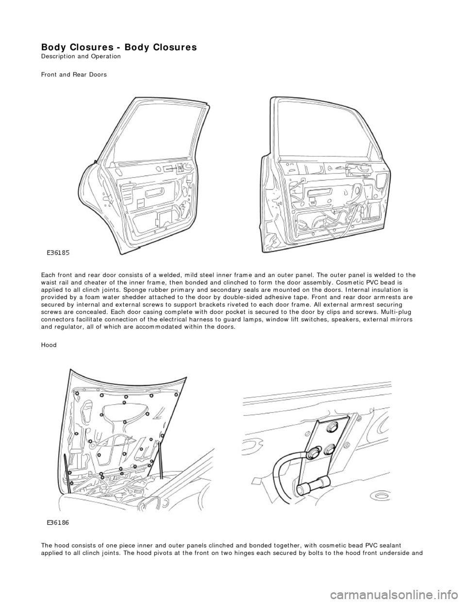
Each front and rear door consists of a welded, mild steel inner frame and an outer panel. The outer panel is welded to the
waist rail and cheater of the inner frame, then bonded and clinched to fo rm the door assembly. Cosmetic PVC bead is
applied to all clinch joints. Sponge rubber primary and secondary seals are mo unted on the doors. Internal insulation is
provided by a foam water shedder attached to the door by double-sided adhesive tape. Front and rear door armrests are
secured by internal and external screws to support brackets riveted to each door frame . All external armrest securing
screws are concealed. Each door casing complete with door po cket is secured to the door by clips and screws. Multi-plug
connectors facilitate connection of the electrical harness to guard lamps, window lift switches, speakers, external mirrors
and regulator, all of which are accommodated within the doors.
Hood
The hood consists of one piece inner an d outer panels clinched and bonded toge ther, with cosmetic bead PVC sealant
applied to all clinch joints. The hood pivo ts at the front on two hinges each secured by bolts to the hood front underside and
Page 2050 of 2490
Body Closures - Luggage Compartment Lid Opening Weatherstrip
Removal and Installation
Removal
Installation
1.
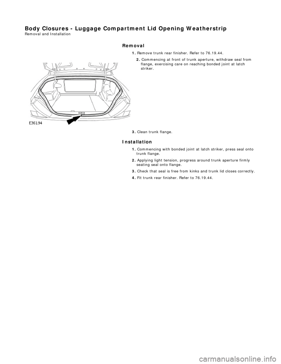
Remove trunk rear finisher. Refer to 76.19.44.
2. Commencing at front of trunk aperture, withdraw seal from
flange, exercising care on re aching bonded joint at latch
striker.
3. Clean trunk flange.
1. Commencing with bonded joint at latch striker, press seal onto
trunk flange.
2. Applying light tension, progress around trunk aperture firmly
seating seal onto flange.
3. Check that seal is free from kinks and trunk lid closes correctly.
4. Fit trunk rear finish er. Refer to 76.19.44.