1998 JAGUAR X308 trunk
[x] Cancel search: trunkPage 38 of 2490

Torque Specifications
Torque sp
ecifications are shown in maintenance procedure illustra
tions and also in the torque specifications chart located at
the front of the relevant section.
Disconnecting/Connecting the Battery
Ow ing t
o the electronic components used on the vehicle, it is important that the battery is disconnected when specified in a
maintenance procedure.
When the battery is connected, the specified procedure must be followed, to ensure the correct operation of all vehicle
systems; refer to Section 414-01.
Use of Control Modules
Control modu les may
only be used on the ve
hicle to which they were originally fitted. Do not attempt to use or test a control
module on any other vehicle.
Function
al Test
On
completion of a maintenance procedure, a thorough test should be carried out, to ensu
re that the relevant vehicle
systems are working correctly.
Protecting the Vehicle
Al ways
fit covers to protect
the fenders before commencing work in the engi ne compartment. Cover the seats and carpets,
wear clean overalls and wash hands or wear gloves before working inside the vehicle. Avoid spilling hydraulic fluid,
antifreeze or battery acid on the paintwork. In the event of spillage, wash off with water imme diately. Use polythene sheets
in the trunk to protect carpets. Always use the recommended service tool, or a satisfactory equivalent, where specified.
Protect temporarily exposed screw thread s by replacing nuts or fitting caps.
Preparation
Before disassembly, clean the surrounding ar ea
as thoroughly as possible. When co
mponents have been removed, blank off
any exposed openings using grease-proof paper and masking tape. Immediately seal fuel, oil and hydraulic lines when
separated, using plastic caps or plugs, to prevent loss of fluid and the entry of dirt. Close the open ends of oilways, exposed
by component removal, with tapered hardw ood plugs or readily visible plastic plugs. Immediately a component is removed,
place it in a suitable container; use a se parate container for each component and its associated pa rts. Before dismantling a
component, clean it thoroughly with a recommended cleaning agent; check that the agent will not damage any of the
materials within the component. Clean the bench and obtain ma rking materials, labels, containers and locking wire before
dismantling a component.
Dismantling
O b
serve scrupulous cleanliness when dismantling components,
particularly when parts of the brake, fuel or hydraulic
systems are being worked on. A particle of dirt or a fragment of cloth could caus e a dangerous malfunction if trapped in
these systems. Clean all tapped holes, crev ices, oilways and fluid passages with compressed air. Do not permit compressed
air to enter an open wound. Always use ey e protection when using compressed air.
Ensure that any O-rings used for sealing are correctly refitted or renewed if disturbed. Mark mating parts to ensure that
they are replaced as dismantled. Whenever possible use markin g materials which avoid the possibilities of causing distortion
or the initiation of cracks, which could occur if a center pu nch or scriber were used. Wire together mating parts where
necessary to prevent accidental interchange (e.g roller bearing components). Tie labels on to all parts to be renewed and to
parts requiring further inspection before being passed fo r reassembly. Place labelled parts and other parts for rebuild in
separate containers. Do not disc ard a part which is due for renewal until it ha s been compared with the new part, to ensure
that the correct part has been obtained.
Page 50 of 2490

Date of
Manufacture
T
h
e date of manufacture (Build Date) of a vehicle is define
d as the calendar month and year in which the bodyshell and
powertrain are combined and the completed vehicle leaves the production line. For certain markets, VIN labels carry the
month and year of manufacture. For other markets, the vehicle Build Date is also displayed on a metal plate located at the
top of the battery tray in the trunk.
ANTI-T
HEFT LABELS
F
or
some markets, anti-theft labels bearing the VIN printed on
a special anti-forgery background are positioned on certain
body components. An additional anti-theft label is positioned on the LH side of the engine/automatic transmission casing.
Anti-theft labels must not be removed from a vehicle unless necessitated by component renewal.
ItemDe scrip
tion
1Gross Vehic
l
e Weight
2Gross Trai
n W
eight
3Maxim
u
m Permitted Front Axle Loading
4Maxim
u
m Permitted Rear Axle Loading
Page 51 of 2490

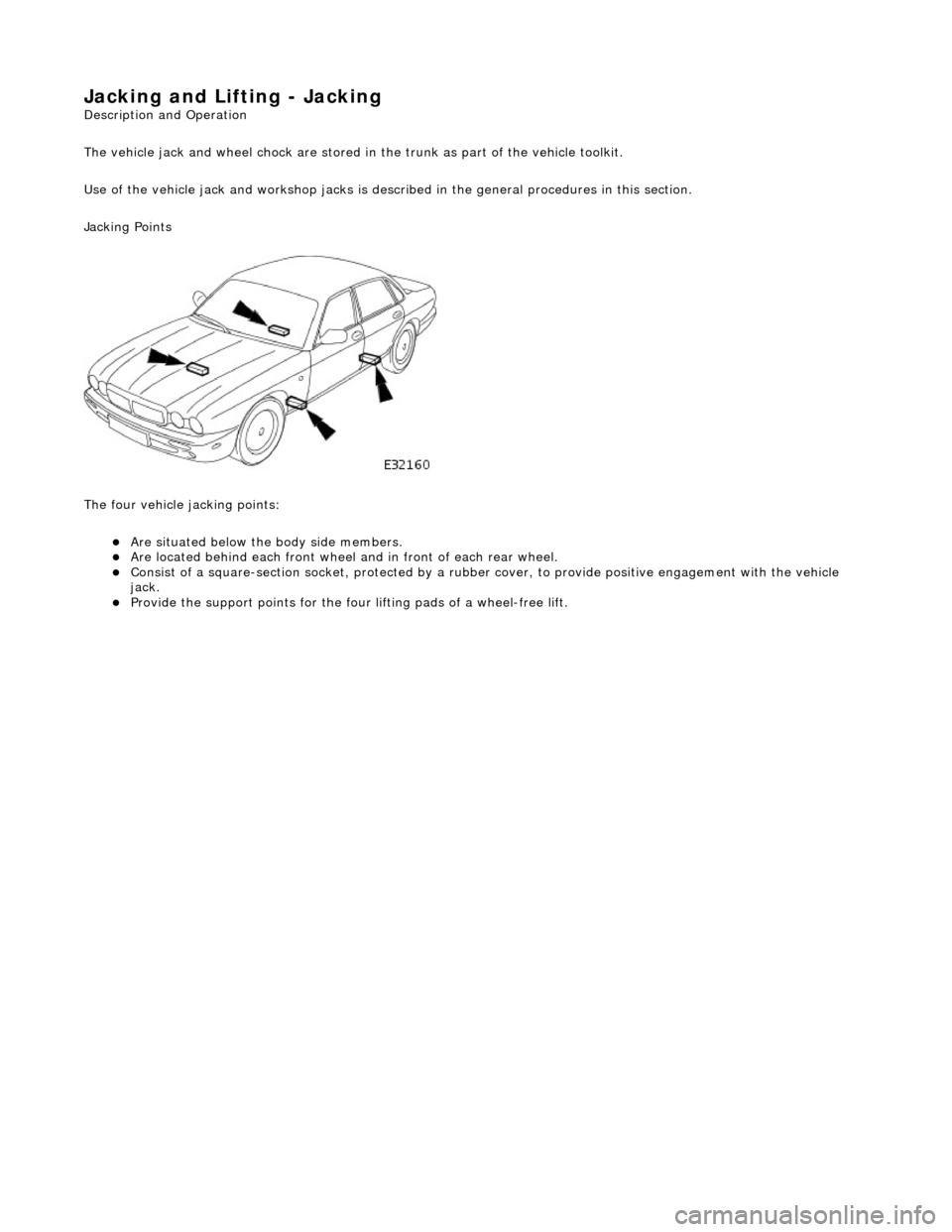
Jacking and Lifting - Jacking
Description an
d Operation
The vehicle jack and wheel chock are stored in the trunk as part of the vehicle toolkit.
Use of the vehicle jack and workshop jacks is desc ribed in the general procedures in this section.
Jacking Points
The four vehicle jacking points:
Are situ
ated below the body side members.
Are l
ocated behind each front wheel
and in front of each rear wheel.
Consist
of a square-section socket, pr
otected by a rubber cover, to provide positive engagement with the vehicle
jack.
Provi
de the support points for the four
lifting pads of a wheel-free lift.
Page 55 of 2490

P
arts List
The front towing point:
Is a welded loop on the ri
ght-ha
nd bumper mounting bracket.
Mus
t only be used when the grille
vane has been removed by turning the three fasteners anti-clockwise.
Rear Towing Point
The rear towing point is a welded loop on the right-hand side of the trunk floor panel; it must not be used for towing
another vehicle.
It
em
Par
t Number
De
scription
1—Fr
ont towing loop
2—Gr
ille vane
3—Gr
ille vane fastener
F
ront Towing Point
Page 275 of 2490

R
equire no adjustment and are non-serviceable items.
Accelerometers
The three accelerometers:
Sense veh
icle body movement.
Gen
erate an analogue voltag
e (maximum +5 volts) proportional to body movement.
Pr
ovide inputs to the adapti
ve damping control module.
The two vertical acce lerometers are mounted on the bulkhead and in the trunk.
The lateral accelerometer is mounted in the ECM housing.
Ada
ptive Damping Control Module (ADCM)
The ADCM
:
Is
mounted on the fascia support bracket.
Controls the four adaptiv
e dampers in re
sponse to analogue and digital inputs.
It
em
De
scription
1Battery su
pply
2Ignition su
pply
3Ground
4Input from verti
cal accelerometer, front
5Input from verti
cal accelerometer, rear
6Input from later
al accelerometer
7F
ootbrake operation signal
8Vehi
cle speed input
9D
amper control signals
10Ou
tput to message center
11D
iagnostic connector serial link
Page 1030 of 2490

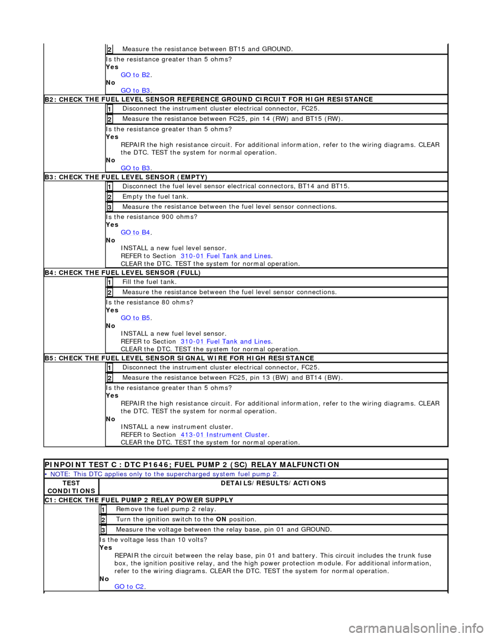
Measure t
he resistance
between BT15 and GROUND.
2
Is the res
istance greater than 5 ohms?
Yes GO to B2
.
No
GO to B3
.
B2: CHECK THE FUEL
LEVEL SENSOR REFERE
NCE GROUND CIRCUIT FOR HIGH RESISTANCE
Disc
onnect the instrument cluster electrical connector, FC25.
1
Meas
ure t
he resistance between FC25, pin 14 (RW) and BT15 (RW).
2
Is the res
istance greater than 5 ohms?
Yes REPAIR the high resistance circui t. For additional information, refer to the wiring diagrams. CLEAR
the DTC. TEST the system for normal operation.
No GO to B3
.
B3: CHECK THE FUEL
LEVEL SENSOR (EMPTY)
Di
sc
onnect the fuel level sensor electrical connectors, BT14 and BT15.
1
Empty the fuel
tank. 2
Measure t
he resistance between the
fuel level sensor connections.
3
Is t
he resistance 900 ohms?
Yes GO to B4
.
No
INST
ALL a new fuel level sensor.
REFER to Section 310
-0 1
Fuel Tank and Lines
.
CLEAR t h
e DTC. TEST the system for normal operation.
B4:
CHECK
THE FUEL LEVEL SENSOR (FULL)
Fi
ll
the fuel tank.
1
Meas
ure t
he resistance between the
fuel level sensor connections.
2
Is
the resistance 80 ohms?
Yes GO to B5
.
No
INST
ALL a new fuel level sensor.
REFER to Section 310
-0 1
Fuel Tank and Lines
.
CLEAR t h
e DTC. TEST the system for normal operation.
B
5
: CHECK THE FUEL LEVEL SENSOR SIGNAL WIRE FOR HIGH RESISTANCE
Di
sc
onnect the instrument cluster electrical connector, FC25.
1
Meas
ure t
he resistance between FC25, pin 13 (BW) and BT14 (BW).
2
Is th
e res
istance greater than 5 ohms?
Yes REPAIR the high resistance circui t. For additional information, refer to the wiring diagrams. CLEAR
the DTC. TEST the system for normal operation.
No INSTALL a new instrument cluster.
REFER to Section 413
-01
Instrume
nt Cluster
.
CLEAR t h
e DTC. TEST the system for normal operation.
P
INPOINT TEST C : DTC P1646; FU
EL PUMP 2 (SC) RELAY MALFUNCTION
•
NO
TE: This DTC applies only to the
supercharged system fuel pump 2.
TES
T
CONDITIONS
D E
TAILS/RESULTS/ACTIONS
C
1
: CHECK THE FUEL PUMP 2 RELAY POWER SUPPLY
R
e
move the fuel pump 2 relay.
1
Turn the ignition swi
t
ch to the
ON position.
2
Meas
ure t
he voltage between the
relay base, pin 01 and GROUND.
3
Is the volt
age less than 10 volts?
Yes REPAIR the circuit between the rela y base, pin 01 and battery. This circuit includes the trunk fuse
box, the ignition positive relay, and the high power protection module. For additional information,
refer to the wiring diagrams. CLEAR the DTC. TEST the system for normal operation.
No GO to C2
.
Page 1031 of 2490

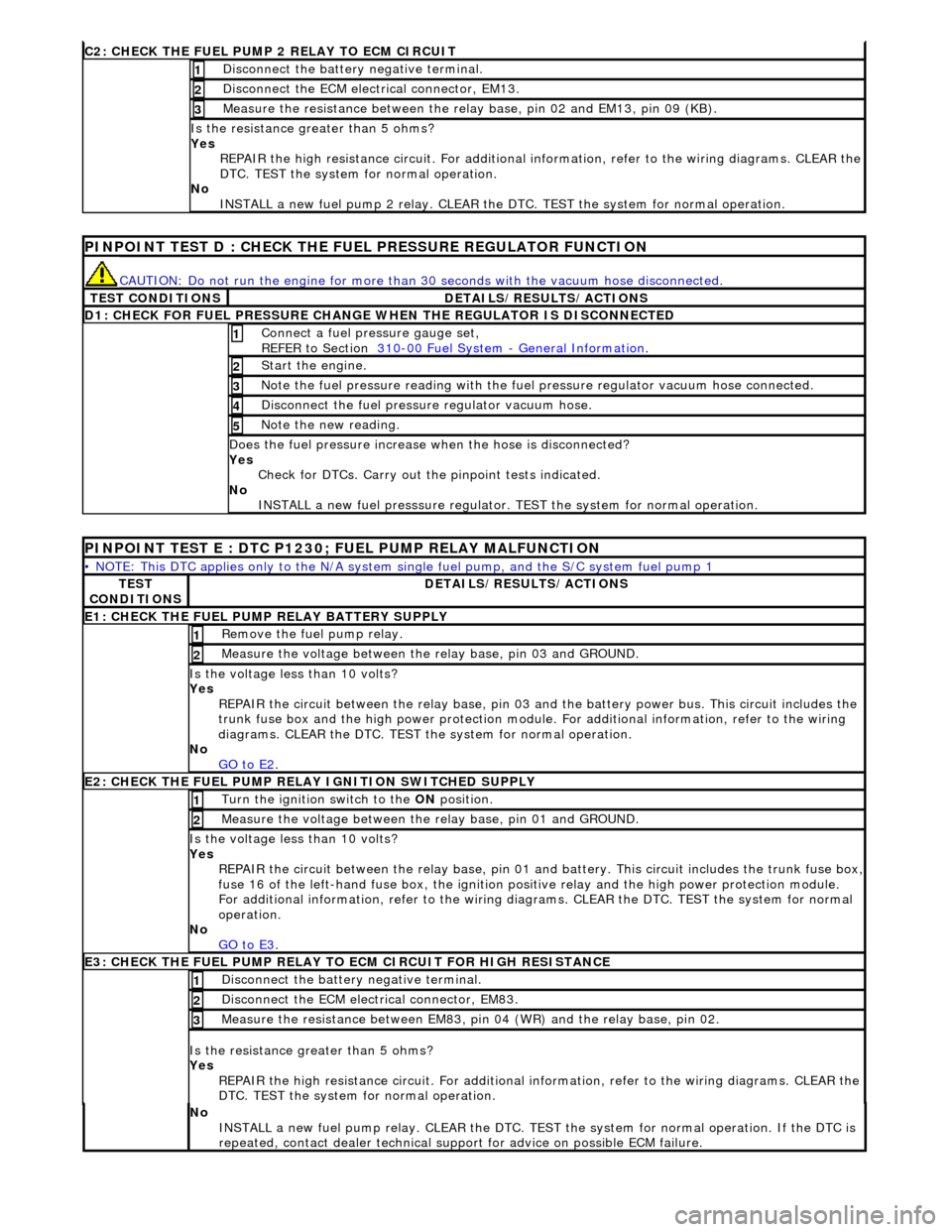
C2: CHECK THE FUEL
PUMP 2 RELAY TO ECM CIRCUIT
Di
sconnect the battery negative terminal.
1
D
isconnect the ECM electrical connector, EM13.
2
Meas
ure the resistance between the rela
y base, pin 02 and EM13, pin 09 (KB).
3
Is th
e resistance greater than 5 ohms?
Yes REPAIR the high resistance circuit. For additional information, refer to the wiring diagrams. CLEAR the
DTC. TEST the system for normal operation.
No INSTALL a new fuel pump 2 relay. CLEAR the DT C. TEST the system for normal operation.
P
INPOINT TEST D : CHECK THE FUEL PRESSURE REGULATOR FUNCTION
CAUTI
ON: Do not run the engine for more than
30 seconds with the vacuum hose disconnected.
T
EST CONDITIONS
D
ETAILS/RESULTS/ACTIONS
D
1: CHECK FOR FUEL PRESSURE CHANGE
WHEN THE REGULATOR IS DISCONNECTED
Connect a
fuel pressure gauge set,
REFER to Section 310
-00
Fuel System
-
General Informati
on
. 1
St
art the engine.
2
N
ote the fuel pressure readin
g with the fuel pressure regu lator vacuum hose connected.
3
Di
sconnect the fuel pressu
re regulator vacuum hose.
4
N
ote the new reading.
5
Doe
s the fuel pressure increase when the hose is disconnected?
Yes Check for DTCs. Carry out the pinpoint tests indicated.
No INSTALL a new fuel presssure regulator. TEST the system for normal operation.
P
INPOINT TEST E : DTC P1230;
FUEL PUMP RELAY MALFUNCTION
•
NOTE: This DTC applies only to the N/A system si
ngle fuel pump, and the S/C system fuel pump 1
TE
ST
CONDITIONS
D
ETAILS/RESULTS/ACTIONS
E1
: CHECK THE FUEL PUMP
RELAY BATTERY SUPPLY
R
emove the fuel pump relay.
1
Meas
ure the voltage between the
relay base, pin 03 and GROUND.
2
Is th
e voltage less than 10 volts?
Yes REPAIR the circuit between the rela y base, pin 03 and the battery power bus. This circuit includes the
trunk fuse box and the high power protection module . For additional information, refer to the wiring
diagrams. CLEAR the DTC. TEST th e system for normal operation.
No GO to E2
.
E2
: CHECK THE FUEL PUMP RELAY IGNITION SWITCHED SUPPLY
Turn the ignition swi
tch to the
ON position.
1
Meas
ure the voltage between the
relay base, pin 01 and GROUND.
2
Is th
e voltage less than 10 volts?
Yes REPAIR the circuit between the rela y base, pin 01 and battery. This circuit includes the trunk fuse box,
fuse 16 of the left-hand fuse box, the ignition po
sitive relay and the high power protection module.
For additional information, refer to the wiring diagrams. CLEAR the DTC. TEST the system for normal
operation.
No GO to E3
.
E3
: CHECK THE FUEL PUMP RELAY TO
ECM CIRCUIT FOR HIGH RESISTANCE
Di
sconnect the battery negative terminal.
1
D
isconnect the ECM electrical connector, EM83.
2
Meas
ure the resistance between EM83, pi
n 04 (WR) and the relay base, pin 02.
3
Is th
e resistance greater than 5 ohms?
Yes REPAIR the high resistance circuit. For additional information, refer to the wiring diagrams. CLEAR the
DTC. TEST the system for normal operation.
No
INSTALL a new fuel pump relay. CLEAR the DTC. TEST the system for normal operation. If the DTC is
repeated, contact dealer technical support for advice on possible ECM failure.
Page 1116 of 2490

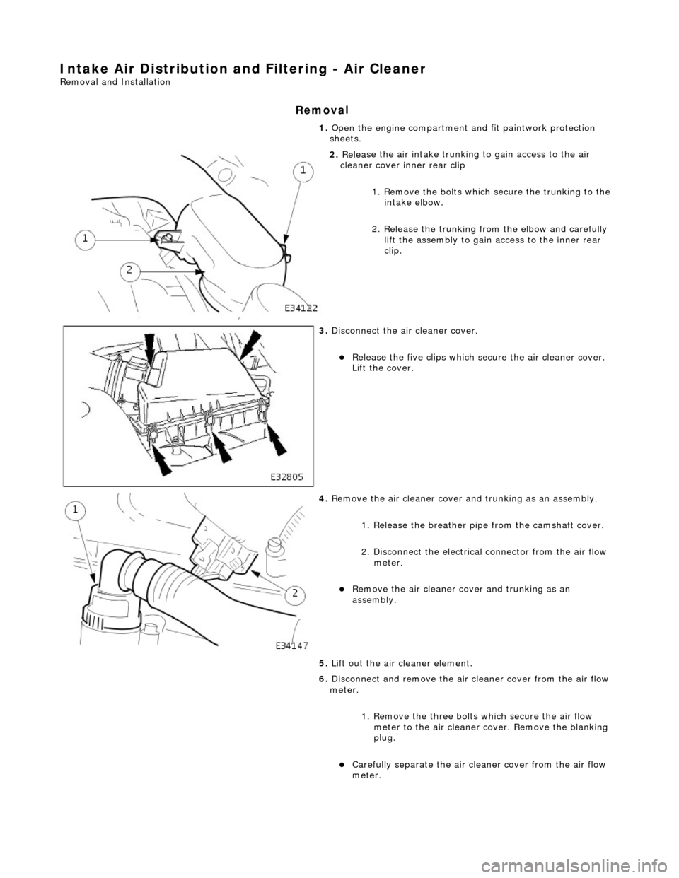
Intake Air Distribution and Filtering - Air Cleaner
Remo
val and Installation
Remov
a
l
1.
Op
en the engine compartment and fit paintwork protection
sheets.
2. Relea
se the air intake trunking
to gain access to the air
cleaner cover inner rear clip
1. Remove the bolts which secure the trunking to the intake elbow.
2. Release the trunking from the elbow and carefully lift the assembly to gain access to the inner rear
clip.
3. Disc
onnect the air cleaner cover.
R
e
lease the five clips which se
cure the air cleaner cover.
Lift the cover.
4. Re
move the air cleaner cover an
d trunking as an assembly.
1. Release the breather pipe from the camshaft cover.
2. Disconnect the electrical connector from the air flow meter.
Re
move the air cleaner cover and trunking as an
assembly.
5. Lift out the air cleaner element.
6. Disconnect and remove the air cleaner cover from the air flow
meter.
1. Remove the three bolts which secure the air flow
meter to the air cleaner co ver. Remove the blanking
plug.
Carefull y separate the ai
r clea
ner cover from the air flow
meter.