1998 JAGUAR X308 fuse diagram
[x] Cancel search: fuse diagramPage 40 of 2490

irri
tation and dermatitis. In addition, used engine oil contains potentially harmful contaminants which may cause skin
cancer. Washing facilities and adequate means of skin protection should be provided.
Observe these recommendations:
Wear pro t
ective clothing and impe
rvious gloves when necessary.
Do not put oily
rags in pockets. Avoid contaminat
ing clothes, particularly underwear, with oil.
Overal
ls must be cleaned re
gularly; discard oil impregna ted clothing and footwear wh ich cannot be washed or
cleaned.
Fi rst
Aid treatment should be obtained
immediately for open cuts or wounds.
Use barrier
creams, applying before each work period, to en
able easier removal of dirty oil and grease from the skin.
Wa
sh with soap and water to ensure th
at all oil is removed (skin cleaner and a nail brush will help). The use of
preparations containing lanolin will help to replace the natural skin oils which have been removed.
Do
not use petrol, kerosene, gas oil, th
inners or solvents for washing skin.
If
skin disorders develop, obtain medical advice immediately.
Wh
ere prac
ticable, degrease components prior to handling.
W
h
ere there is a risk of fluids coming into contact with th
e eyes, suitable eye protection should be worn - goggles or
face shield. An eye wash facility should be provided.
Ensure that a
dequate ventilation is provided when volatile degreasing agents are being used.
E
n
vironmental Protection
In so
m
e countries it is illegal to pour used oil onto the ground
, down sewers or drains, or into water courses. The burning of
used engine oil in small space heaters or boilers is not reco mmended unless emission control equipment is fitted. Dispose of
used oil through authorized waste disposal contractors, to licensed waste disposal sites or to the waste oil reclamation
trade. If in doubt, contact the Local Authority for advice on disposal facilities.
On-Board Diagnostics (OBD)
Ve
hicles use programmed electronic control systems to prov
ide engine management and emission regulation, automatic
transmission operation and anti -lock braking control. These control systems ha ve an integral On-Board Diagnostics (OBD)
facility for use in conjunction with either Jaguar diagnostic equipment or a scan t ool which is capable of retrieving DTCs,
PIDs and performing active commands.
The OBD information in this manual provid es diagnostic and rectification procedures for emission related electrical and
mechanical systems. The informat ion is intended to facilitate fault diagnosis and the subsequent rectification of vehicles
without recourse to the portab le diagnostic unit (PDU).
OBD related information can be fo und in the following sections:
General Information
Engine M
anagement System
Auto
matic Transmission
Anti-lock Br
aking System
Where appropriate a section comprises the following sub-sections:
Description and Operation
A ge
neral illustration and parts list to help the identi
fication of the particular system or component.
A b
rief description of the system operating characteristics and monitoring procedure
accompanied by a component
illustration.
Addi ti
onal information, where appropriat
e, is provided in the form of component calibrations, characteristics and
cross sectional views.
A localized circui
t diagram is included to provide circuit iden
tification and details of connectors, splices, fuses, wire
gauge and colors. See Circuit Diagrams.
Diagnosis and Testing (dedicated to fault analysis and rectification)
Recommended special tools. Symptom chart; a ch
art contai
ning all relevant Diagnostic Trouble Code s (DTC), their possible causes and an
indication of the appropriate test.
Sp
ecific pinpoint test(s), de
signed so that fault diagnosis can be carr ied out in a logical and efficient manner.
Page 278 of 2490
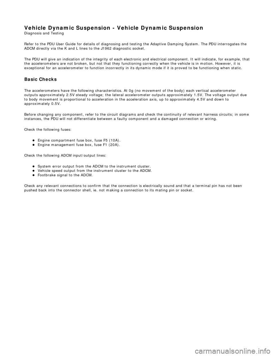
Vehicle Dynamic Suspension - Vehicle Dynamic Suspension
Diagn
osis and Testing
Refer to the PDU User Guide for details of diagnosing and testing the Adaptive Damping System. The PDU interrogates the
ADCM directly via the K and L lines to the J1962 diagnostic socket.
The PDU will give an indication of the integrity of each electron ic and electrical component. It will indicate, for example, that
the accelerometers are not broken, but not that they functionin g correctly when the vehicle is in motion. However, it is
exceptional for an accelero meter to function incorrectly in its dynamic mode if it is proved to be functioning when static.
Basic Checks
The accele
rometers have the following ch
aracteristics. At 0g (no movement of the body) each vertical accelerometer
outputs approximately 2.5V steady voltage; the lateral acce lerometer outputs approximately 1.5V. The voltage output due
to body movement is proportional to acceleration in the acceleration axis, up to approximately 4.5V and down to
approximately 0.5V.
Before changing any component, refer to the circuit diagrams and check the cont inuity of relevant harness circuits; in some
instances, the PDU will not different iate between a faulty component an d a damaged connection or wiring.
Check the following fuses:
En
gine compartment fuse
box, fuse F5 (10A).
Engine m
anagement fuse
box, fuse F1 (20A).
Check the following ADCM input/output lines:
Sy stem erro
r output from the ADCM
to the instrument cluster.
Vehicl
e speed output from the inst
rument cluster to the ADCM.
Foo
tbrake signal to the ADCM.
Check any relevant connections to confirm that the connection is electrically sound and that a terminal pin has not been
pushed back into the connector shell, ie. not ma king a connection to its mating pin or socket.
Page 1017 of 2490
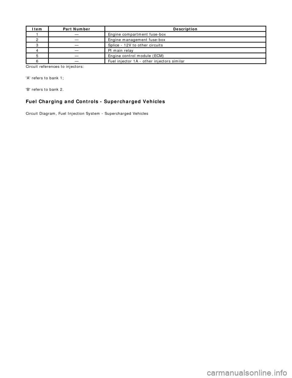
Ci
rcuit references to injectors:
'A' refers to bank 1;
'B' refers to bank 2.
Fuel C
harging and Controls - Supercharged Vehicles
Ci
rcuit Diagram, Fuel Injection
System - Supercharged Vehicles
It
em
Par
t Number
De
scription
1—E
ngine compartment fuse-box
2—Engine
management fuse-box
3—Splice
- 12V to
other circuits
4—PI m
ain relay
5—Engine
control module (ECM)
6—Fue
l injector 1A - other injectors similar
Page 1029 of 2490
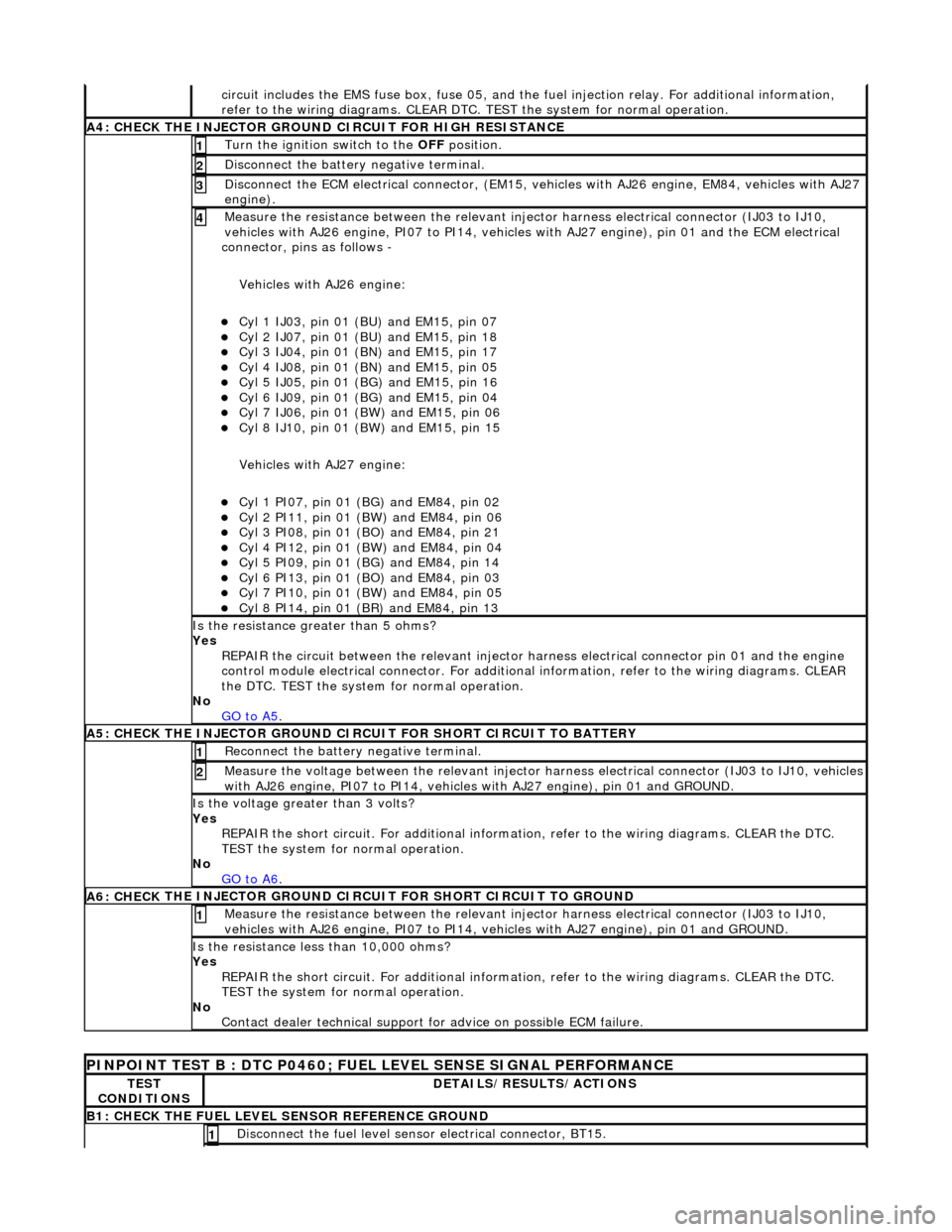
ci
rcuit includes the EMS fuse box,
fuse 05, and the fuel injection relay. For additional information,
refer to the wiring diagrams. CLEAR DTC. TEST the system for normal operation.
A4: CHECK
THE INJECTOR GROUND
CIRCUIT FOR HIGH RESISTANCE
Turn the ignition swi
tch to the OFF
position.
1
Di
sconnect the battery negative terminal.
2
D
isconnect the ECM electrical connector, (EM15, vehi
cles with AJ26 engine, EM84, vehicles with AJ27
engine).
3
Meas
ure the resistance between the relevant injector harness electrical connector (IJ03 to IJ10,
vehicles with AJ26 engine, PI07 to PI14, vehicles with AJ27 engine), pin 01 and the ECM electrical
connector, pins as follows -
Vehicles with AJ26 engine:
Cy
l 1 IJ03, pin 01 (BU) and EM15, pin 07
Cy
l 2 IJ07, pin 01 (BU) and EM15, pin 18
Cy
l 3 IJ04, pin 01 (BN) and EM15, pin 17
Cy
l 4 IJ08, pin 01 (BN) and EM15, pin 05
Cy
l 5 IJ05, pin 01 (BG) and EM15, pin 16
Cy
l 6 IJ09, pin 01 (BG) and EM15, pin 04
Cy
l 7 IJ06, pin 01 (BW) and EM15, pin 06
Cy
l 8 IJ10, pin 01 (BW) and EM15, pin 15
Vehicles with AJ27 engine:
Cy
l 1 PI07, pin 01 (B
G) and EM84, pin 02
Cy
l 2 PI11, pin 01 (BW) and EM84, pin 06
Cy
l 3 PI08, pin 01 (BO) and EM84, pin 21
Cy
l 4 PI12, pin 01 (BW) and EM84, pin 04
Cy
l 5 PI09, pin 01 (B
G) and EM84, pin 14
Cy
l 6 PI13, pin 01 (BO) and EM84, pin 03
Cy
l 7 PI10, pin 01 (BW) and EM84, pin 05
Cy
l 8 PI14, pin 01 (BR) and EM84, pin 13
4
Is th
e resistance greater than 5 ohms?
Yes REPAIR the circuit between the relevant injector harness electrical connector pin 01 and the engine
control module electrical connecto r. For additional information, refer to the wiring diagrams. CLEAR
the DTC. TEST the system for normal operation.
No GO to A5
.
A5: CHECK
THE INJECTOR GROUND CI
RCUIT FOR SHORT CIRCUIT TO BATTERY
R
econnect the battery negative terminal.
1
Meas
ure the voltage between the relevant injector harness electrical connector (IJ03 to IJ10, vehicles
with AJ26 engine, PI07 to PI14, vehicles with AJ27 engine), pin 01 and GROUND.
2
Is th
e voltage greater than 3 volts?
Yes REPAIR the short circuit. For addi tional information, refer to the wiring diagrams. CLEAR the DTC.
TEST the system for normal operation.
No GO to A6
.
A6: CHECK
THE INJECTOR GROUND CI
RCUIT FOR SHORT CIRCUIT TO GROUND
Meas
ure the resistance between the relevant injector harness electrical connector (IJ03 to IJ10,
vehicles with AJ26 engine, PI07 to PI14, vehicles with AJ27 engine), pin 01 and GROUND.
1
Is
the resistance less than 10,000 ohms?
Yes REPAIR the short circuit. For addi tional information, refer to the wiring diagrams. CLEAR the DTC.
TEST the system for normal operation.
No Contact dealer technical support for advice on possible ECM failure.
P
INPOINT TEST B : DTC P0460; FUEL
LEVEL SENSE SIGNAL PERFORMANCE
TE
ST
CONDITIONS
D
ETAILS/RESULTS/ACTIONS
B1: CHECK
THE FUEL LEVEL SENSOR REFERENCE GROUND
Di
sconnect the fuel level sensor electrical connector, BT15.
1
Page 1030 of 2490
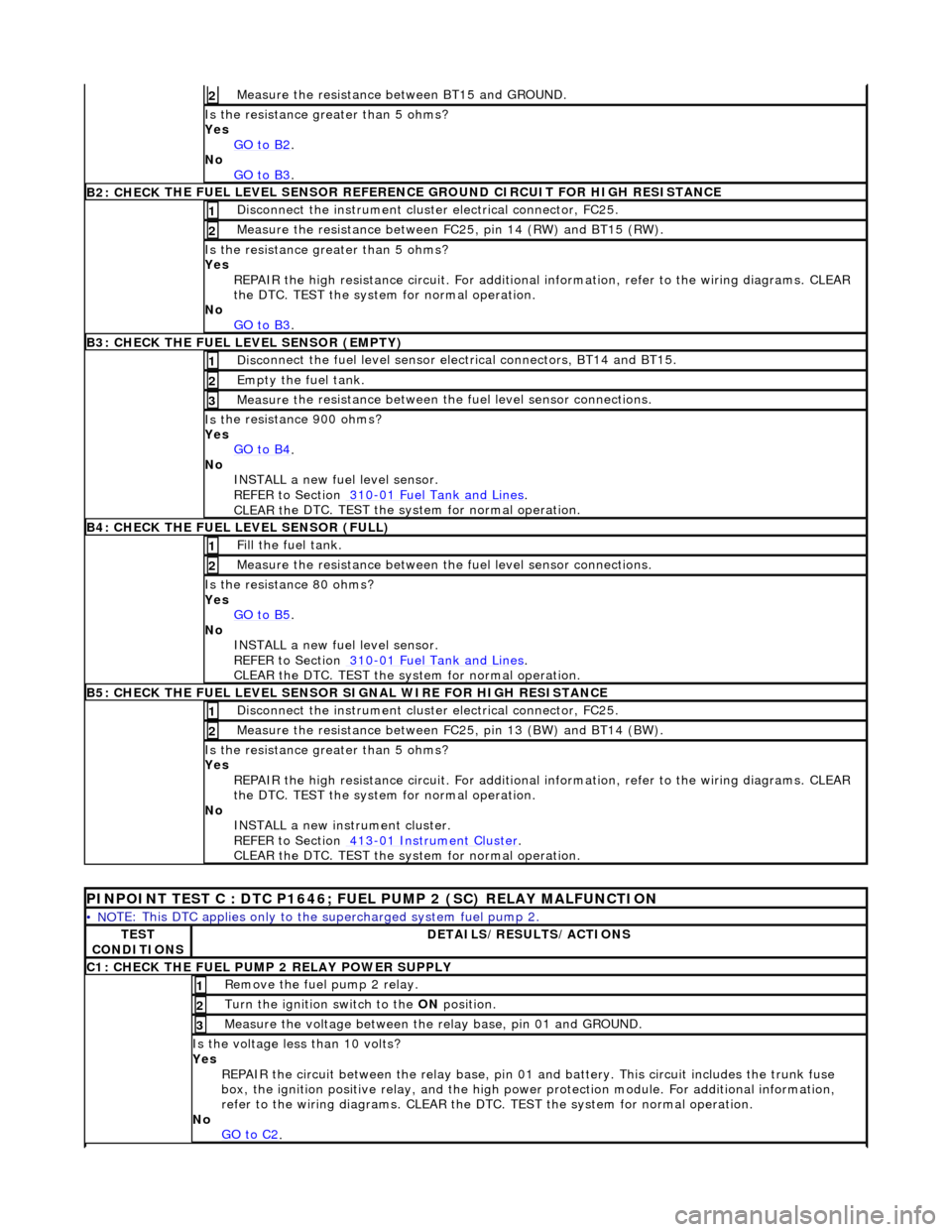
Measure t
he resistance
between BT15 and GROUND.
2
Is the res
istance greater than 5 ohms?
Yes GO to B2
.
No
GO to B3
.
B2: CHECK THE FUEL
LEVEL SENSOR REFERE
NCE GROUND CIRCUIT FOR HIGH RESISTANCE
Disc
onnect the instrument cluster electrical connector, FC25.
1
Meas
ure t
he resistance between FC25, pin 14 (RW) and BT15 (RW).
2
Is the res
istance greater than 5 ohms?
Yes REPAIR the high resistance circui t. For additional information, refer to the wiring diagrams. CLEAR
the DTC. TEST the system for normal operation.
No GO to B3
.
B3: CHECK THE FUEL
LEVEL SENSOR (EMPTY)
Di
sc
onnect the fuel level sensor electrical connectors, BT14 and BT15.
1
Empty the fuel
tank. 2
Measure t
he resistance between the
fuel level sensor connections.
3
Is t
he resistance 900 ohms?
Yes GO to B4
.
No
INST
ALL a new fuel level sensor.
REFER to Section 310
-0 1
Fuel Tank and Lines
.
CLEAR t h
e DTC. TEST the system for normal operation.
B4:
CHECK
THE FUEL LEVEL SENSOR (FULL)
Fi
ll
the fuel tank.
1
Meas
ure t
he resistance between the
fuel level sensor connections.
2
Is
the resistance 80 ohms?
Yes GO to B5
.
No
INST
ALL a new fuel level sensor.
REFER to Section 310
-0 1
Fuel Tank and Lines
.
CLEAR t h
e DTC. TEST the system for normal operation.
B
5
: CHECK THE FUEL LEVEL SENSOR SIGNAL WIRE FOR HIGH RESISTANCE
Di
sc
onnect the instrument cluster electrical connector, FC25.
1
Meas
ure t
he resistance between FC25, pin 13 (BW) and BT14 (BW).
2
Is th
e res
istance greater than 5 ohms?
Yes REPAIR the high resistance circui t. For additional information, refer to the wiring diagrams. CLEAR
the DTC. TEST the system for normal operation.
No INSTALL a new instrument cluster.
REFER to Section 413
-01
Instrume
nt Cluster
.
CLEAR t h
e DTC. TEST the system for normal operation.
P
INPOINT TEST C : DTC P1646; FU
EL PUMP 2 (SC) RELAY MALFUNCTION
•
NO
TE: This DTC applies only to the
supercharged system fuel pump 2.
TES
T
CONDITIONS
D E
TAILS/RESULTS/ACTIONS
C
1
: CHECK THE FUEL PUMP 2 RELAY POWER SUPPLY
R
e
move the fuel pump 2 relay.
1
Turn the ignition swi
t
ch to the
ON position.
2
Meas
ure t
he voltage between the
relay base, pin 01 and GROUND.
3
Is the volt
age less than 10 volts?
Yes REPAIR the circuit between the rela y base, pin 01 and battery. This circuit includes the trunk fuse
box, the ignition positive relay, and the high power protection module. For additional information,
refer to the wiring diagrams. CLEAR the DTC. TEST the system for normal operation.
No GO to C2
.
Page 1031 of 2490
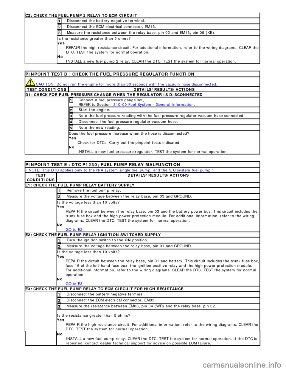
C2: CHECK THE FUEL
PUMP 2 RELAY TO ECM CIRCUIT
Di
sconnect the battery negative terminal.
1
D
isconnect the ECM electrical connector, EM13.
2
Meas
ure the resistance between the rela
y base, pin 02 and EM13, pin 09 (KB).
3
Is th
e resistance greater than 5 ohms?
Yes REPAIR the high resistance circuit. For additional information, refer to the wiring diagrams. CLEAR the
DTC. TEST the system for normal operation.
No INSTALL a new fuel pump 2 relay. CLEAR the DT C. TEST the system for normal operation.
P
INPOINT TEST D : CHECK THE FUEL PRESSURE REGULATOR FUNCTION
CAUTI
ON: Do not run the engine for more than
30 seconds with the vacuum hose disconnected.
T
EST CONDITIONS
D
ETAILS/RESULTS/ACTIONS
D
1: CHECK FOR FUEL PRESSURE CHANGE
WHEN THE REGULATOR IS DISCONNECTED
Connect a
fuel pressure gauge set,
REFER to Section 310
-00
Fuel System
-
General Informati
on
. 1
St
art the engine.
2
N
ote the fuel pressure readin
g with the fuel pressure regu lator vacuum hose connected.
3
Di
sconnect the fuel pressu
re regulator vacuum hose.
4
N
ote the new reading.
5
Doe
s the fuel pressure increase when the hose is disconnected?
Yes Check for DTCs. Carry out the pinpoint tests indicated.
No INSTALL a new fuel presssure regulator. TEST the system for normal operation.
P
INPOINT TEST E : DTC P1230;
FUEL PUMP RELAY MALFUNCTION
•
NOTE: This DTC applies only to the N/A system si
ngle fuel pump, and the S/C system fuel pump 1
TE
ST
CONDITIONS
D
ETAILS/RESULTS/ACTIONS
E1
: CHECK THE FUEL PUMP
RELAY BATTERY SUPPLY
R
emove the fuel pump relay.
1
Meas
ure the voltage between the
relay base, pin 03 and GROUND.
2
Is th
e voltage less than 10 volts?
Yes REPAIR the circuit between the rela y base, pin 03 and the battery power bus. This circuit includes the
trunk fuse box and the high power protection module . For additional information, refer to the wiring
diagrams. CLEAR the DTC. TEST th e system for normal operation.
No GO to E2
.
E2
: CHECK THE FUEL PUMP RELAY IGNITION SWITCHED SUPPLY
Turn the ignition swi
tch to the
ON position.
1
Meas
ure the voltage between the
relay base, pin 01 and GROUND.
2
Is th
e voltage less than 10 volts?
Yes REPAIR the circuit between the rela y base, pin 01 and battery. This circuit includes the trunk fuse box,
fuse 16 of the left-hand fuse box, the ignition po
sitive relay and the high power protection module.
For additional information, refer to the wiring diagrams. CLEAR the DTC. TEST the system for normal
operation.
No GO to E3
.
E3
: CHECK THE FUEL PUMP RELAY TO
ECM CIRCUIT FOR HIGH RESISTANCE
Di
sconnect the battery negative terminal.
1
D
isconnect the ECM electrical connector, EM83.
2
Meas
ure the resistance between EM83, pi
n 04 (WR) and the relay base, pin 02.
3
Is th
e resistance greater than 5 ohms?
Yes REPAIR the high resistance circuit. For additional information, refer to the wiring diagrams. CLEAR the
DTC. TEST the system for normal operation.
No
INSTALL a new fuel pump relay. CLEAR the DTC. TEST the system for normal operation. If the DTC is
repeated, contact dealer technical support for advice on possible ECM failure.
Page 1064 of 2490
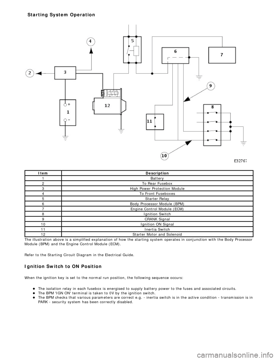
The il
lustration above is a simplified expl
anation of how the starting system operates in conjunction with the Body Processor
Module (BPM) and the Engine Control Module (ECM).
Refer to the Starting Circuit Diagram in the Electrical Guide.
I g
nition Switch to ON Position
W
h
en the ignition key is set to the normal run position, the following sequence occurs:
The
is
olation relay in each fusebox is
energised to supply battery power to the fuses and associated circuits.
The BPM 'IGN
ON' terminal
is taken to 0V by the ignition switch.
The BPM
checks that various parameters are correct e.g. -
inertia switch is in the active condition - transmission is in
PARK - security system has been correctly disabled.
It e
m
De
scr
iption
1Batt
ery
2To Re ar
Fusebox
3Hi
gh Power Pr
otection Module
4To Front
Fu
seboxes
5Starter Re
lay
6Body Processor M
odule (BPM)
7Engine
C
ontrol Module (ECM)
8Ignition Switch
9CRANK Signal
10Ignition ON Signal
11Inertia Switch
12St
arte
r Motor and Solenoid
Starting System Operation
Page 1065 of 2490
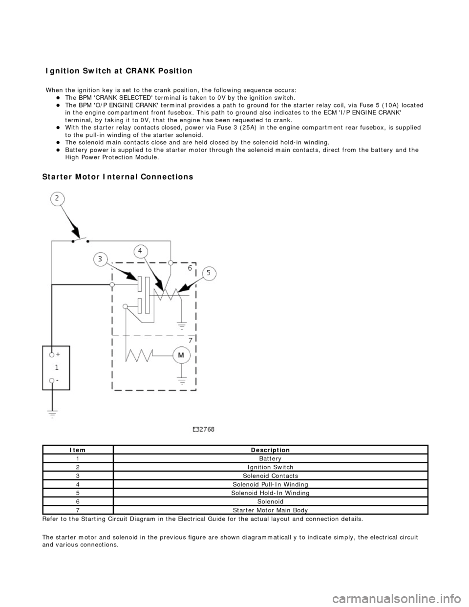
The BPM
'CRANK SELECTED' terminal is ta
ken to 0V by the ignition switch.
The BPM
'O/P ENGINE CRANK' terminal pr
ovides a path to ground for the starte r relay coil, via Fuse 5 (10A) located
in the engine compartment front fusebo x. This path to ground also indicates to the ECM 'I/P ENGINE CRANK'
terminal, by taking it to 0V, that the engine has been requested to crank.
Wi
th the starter relay contacts closed,
power via Fuse 3 (25A) in the engine compartment rear fusebox, is supplied
to the pull-in winding of the starter solenoid.
The s
olenoid main contacts close and are held
closed by the solenoid hold-in winding.
Battery power is supplied
to
the starter motor through the solenoid main contacts, direct from the battery and the
High Power Protection Module.
Starter
Motor Internal Connections
Re
fer to the Starting Circuit Diagram in the Electrical
Guide for the actual layout and connection details.
The starter motor and solenoid in the previous figure are shown diagrammaticall y to indicate simply, the electrical circuit
and various connections.
It
em
De
scription
1Batt
ery
2Ignition Switch
3So
lenoid Contacts
4So
lenoid Pull-In Winding
5So
lenoid Hold-In Winding
6So
lenoid
7St
arter Motor Main Body
I
gnition Switch at CRANK Position
W
hen the ignition key is set to the crank position, the following sequence occurs: