1998 JAGUAR X308 headlamps
[x] Cancel search: headlampsPage 516 of 2490
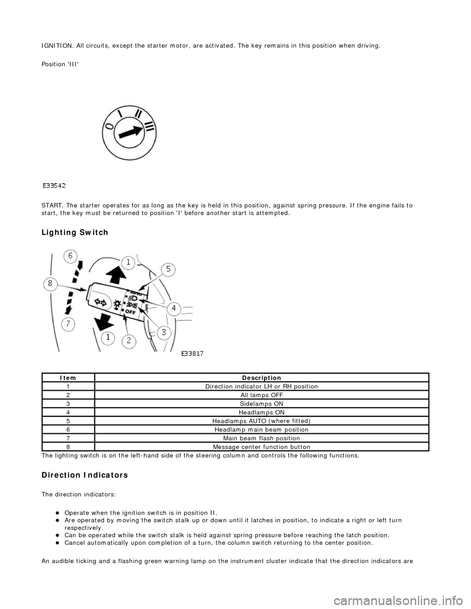
IGNITION.
All circuits, except the star
ter motor, are activated. The key rema ins in this position when driving.
Position 'III'
START. The starter operates for as long as the key is held in this position, ag ainst spring pressure. If the engine fails to
start, the key must be returned to position 'I' befo re another start is attempted.
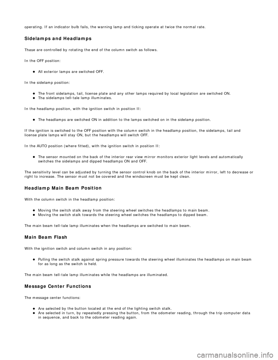
Lighting Switch
The li
ghting switch is on the left-h
and side of the steering column and controls the following functions.
Direction Indicators
The direction in
dicators:
Operate
when the ignition switch is in position II.
Are operat
ed by movi
ng the switch stalk up or down until it latches in position, to in
dicate a right or left turn
respectively.
Can be o p
erated while the switch stalk is held against
spring pressure before reaching the latch position.
Cancel
automatically upon completion of a turn, the
column switch returning to the center position.
An audible ticking and a flashing green warning lamp on the in strument cluster indicate that the direction indicators are
Ite
m
De
scr
iption
1D
i
rection indicator LH or RH position
2All lamps OFF
3Side
lamps ON
4Headlamps ON
5Headlamps AUT O
(where fitted)
6He
adlam
p main beam position
7Mai
n
beam flash position
8M
e
ssage center function button
Page 517 of 2490
o
perating. If an indicator bulb fails, the warning
lamp and ticking operate at twice the normal rate.
Sidelam
ps and Headlamps
Thes
e are controlled by rotating the end of the column switch as follows.
In the OFF position:
All
exterior lamps are switched OFF.
In the sidelamp position:
The front
sidelamps, tail, license plate and any other la
mps required by local legislation are switched ON.
The
sidelamps tell-tale lamp illuminates.
In the headlamp position, with the ignition switch in position II:
The h
eadlamps are switched ON in addition to the lamps switched on in the sidelamp position.
If the ignition is switched to the OFF position with the column switch in the headlamp position, the sidelamps, tail and
license plate lamps will stay ON, but the headlamps will switch OFF.
In the AUTO position (where fitted), with the ignition switch in position II:
Th
e sensor mounted on the back of the interior rear view
mirror monitors exterior light levels and automatically
switches the sidelamps and di pped headlamps ON and OFF.
The sensitivity level can be adjusted by turn ing the sensor control knob on the back of the interior mirror, left to decrease or
right to increase. The sensor must not be covered and the windscreen must be kept clean.
Headlamp Main Bea
m Position
Wi
th the column switch in
the headlamp position:
Movin
g the switch stalk away fro
m the steering wheel switches the headlamps to main beam.
Movin
g the switch stalk towards the steering wheel switches the headlamps to dipped beam.
The main beam tell-tale lamp illuminates when the headlamps are switched to main beam.
Ma
in Beam Flash
Wi
th the ignition switch and column switch in any position:
Pulling the
switch stalk agains
t spring pressure towards th e steering wheel illuminates the headlamps on main beam
for as long as the switch is held.
The main beam tell-tale lamp illuminates while the headlamps are illuminated.
M
essage Center Functions
T
he message center functions:
Are se
lected by the button located at the end of the lighting switch stalk.
Are se
lected in turn, by repeatedly pressing the button,
from the odometer reading, through the trip computer data
in sequence, and back to th e odometer reading again.
Page 1919 of 2490
Exterior Lighting - Exterior Lighting
Description and Operation
A multi-function switch located on the left stalk of the steering column switch assembly permits selection of either parking
(side), headlamps, auto-headlamp or off. Selection of a particular mode provides the appropriate input to the body
processor module (BPM).
Where the auto headlamp function is incorporated, a light sensor in the interior rear view mirror monitors ambient light and
provides an input to the BPM. The BPM responds by switching the low beam headlamps on or off as appropriate for the
prevailing light conditions.
The front and rear fog lamp switch is located on the fascia outboard of the steering column.
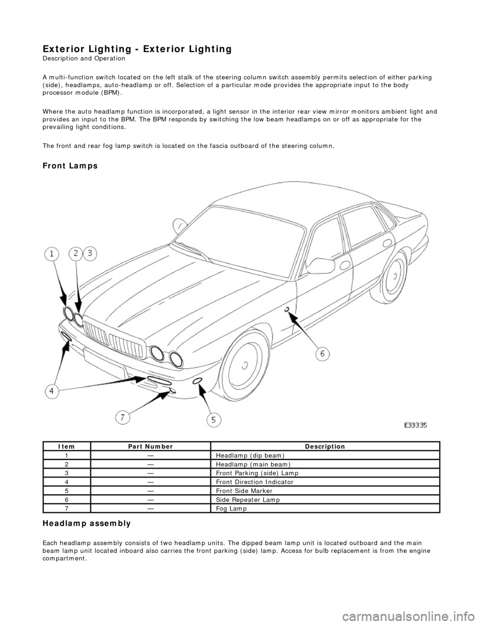
Front Lamps
Headlamp assembly
Each headlamp assembly consists of tw o headlamp units. The dipped beam lamp unit is located outboard and the main
beam lamp unit located inboard also carries the front parking (side) lamp. Access for bulb replacement is from the engine
compartment.
ItemPart NumberDescription
1—Headlamp (dip beam)
2—Headlamp (main beam)
3—Front Parking (side) Lamp
4—Front Direction Indicator
5—Front Side Marker
6—Side Repeater Lamp
7—Fog Lamp
Page 1978 of 2490
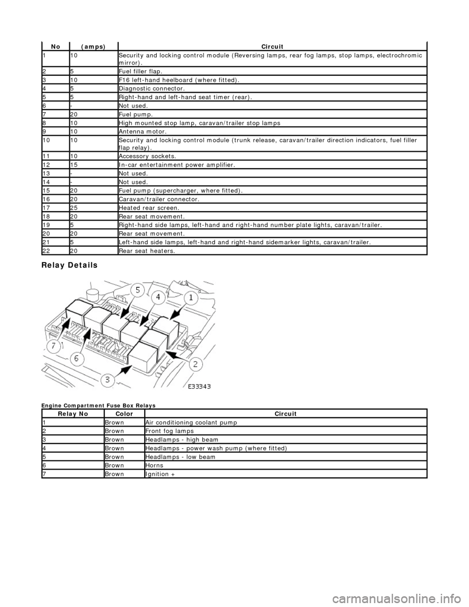
Relay Details
Engine Compartment Fuse Box Relays
No(amps)Circuit
110Security and locking control module (Reversing lamps, rear fog lamps, stop lamps, electrochromic
mirror).
25Fuel filler flap.
310F16 left-hand heelboard (where fitted).
45Diagnostic connector.
55Right-hand and left-han d seat timer (rear).
6-Not used.
720Fuel pump.
810High mounted stop lamp, caravan/trailer stop lamps
910Antenna motor.
1010Security and locking control module (trunk release, caravan/trailer direction indicators, fuel filler
flap relay).
1110Accessory sockets.
1215In-car entertainment power amplifier.
13-Not used.
14-Not used.
1520Fuel pump (supercharger, where fitted).
1620Caravan/trailer connector.
1725Heated rear screen.
1820Rear seat movement.
195Right-hand side lamps, left-h and and right-hand number pl ate lights, caravan/trailer.
2020Rear seat movement.
215Left-hand side lamps, left-hand and right-hand sidemarker lights, caravan/trailer.
2220Rear seat heaters.
Relay NoColorCircuit
1BrownAir conditioning coolant pump
2BrownFront fog lamps
3BrownHeadlamps - high beam
4BrownHeadlamps - power wash pump (where fitted)
5BrownHeadlamps - low beam
6BrownHorns
7BrownIgnition +
Page 2274 of 2490
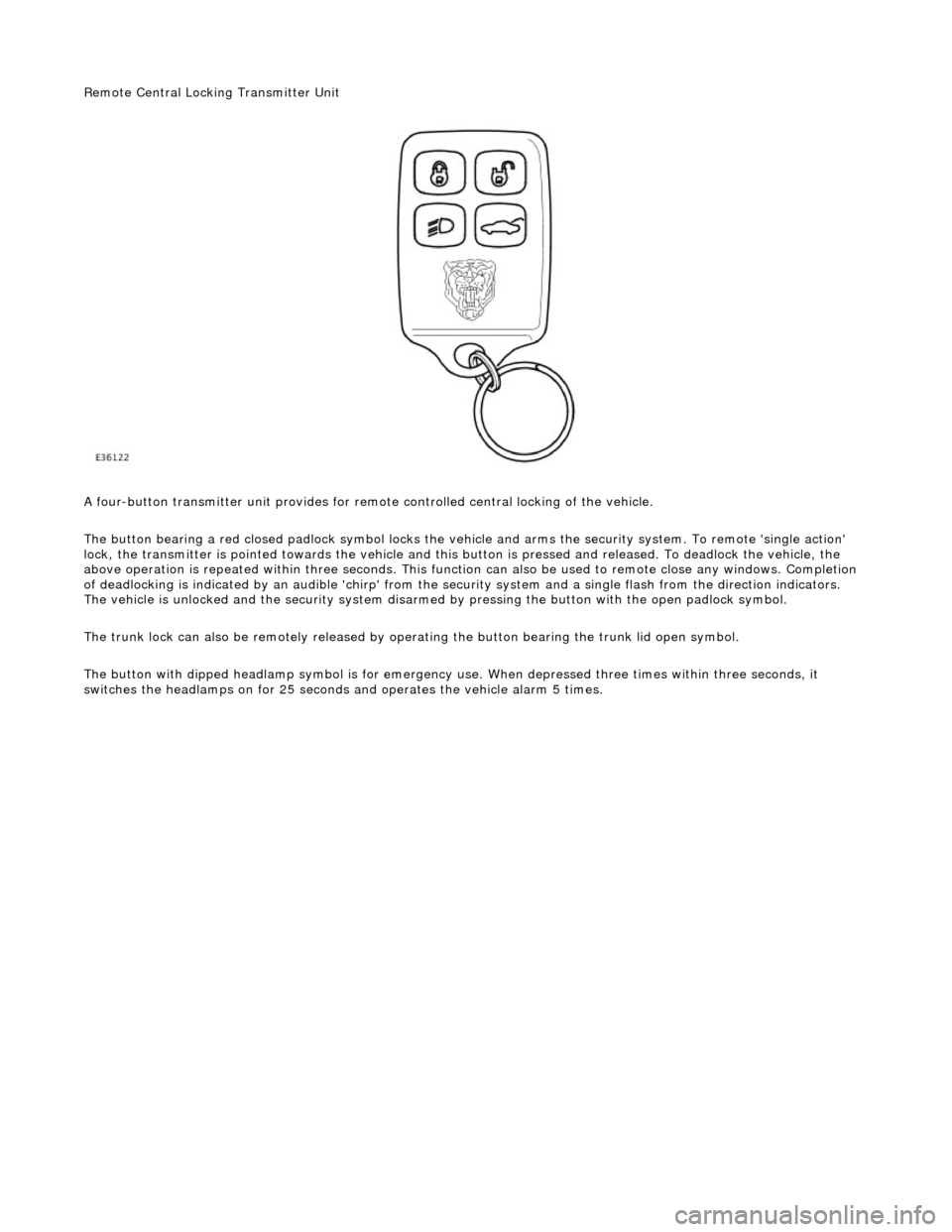
Remote Central Locking Transmitter Unit
A four-button transmitter unit provides for remote controlled central locking of the vehicle.
The button bearing a red closed padlock sy mbol locks the vehicle and arms the security system. To remote 'single action'
lock, the transmitter is pointed towards the vehicle and this bu tton is pressed and released. To deadlock the vehicle, the
above operation is repeated with in three seconds. This function can also be used to remote close any windows. Completion
of deadlocking is indicated by an audible 'chirp' from the security system and a single flash from the direction indicators.
The vehicle is unlocked and the security system disarmed by pressing the button with the open padlock symbol.
The trunk lock can also be remotely released by op erating the button bearing the trunk lid open symbol.
The button with dipped headlamp symbol is for emergency us e. When depressed three times within three seconds, it
switches the headlamps on for 25 seconds and operates the vehicle alarm 5 times.
Page 2348 of 2490
1.
WARNING: ENSURE THAT ALL PERSONNEL AND
EQUIPMENT ARE CLEAR OF AREA BEFORE OPERATING RAMP.
Carefully slide bumper assembly onto fender guide blocks.
2. Raise ramp to working height.
3. Install but do not fully tighten bo lts securing bumper to struts.
4. Check clearance between top of bumper and bottom of fender.
If necessary, remove bumper, adjust guide blocks to achieve
correct clearance and refit bumper.
5. Connect harness multiplugs to foglamps, direction indicators
and where fitted side marker lamps.
6. Install harnesses in retaining clips at each side of cover.
7. Install powerwash hoses to jet assemblies and secure with new
plastic clips. Refer to Section 501.16.
8. Install radiator grill and su rround. refer to 76.55.03 and
76.55.15.
9. Check and as necessary adjust bumper cover to fender,
headlamps and radiator grill surround clearances. Refer to
Description and Operation in this section.
10. Fully tighten bumper assembly to strut securing bolts.
11. Install wheelarch liners.
12. Install undertray. Refer to 76.22.90.
13. Lower 4-post ramp.
14. Install road wheels and lower wheel-free lifts.
Page 2351 of 2490
Installation
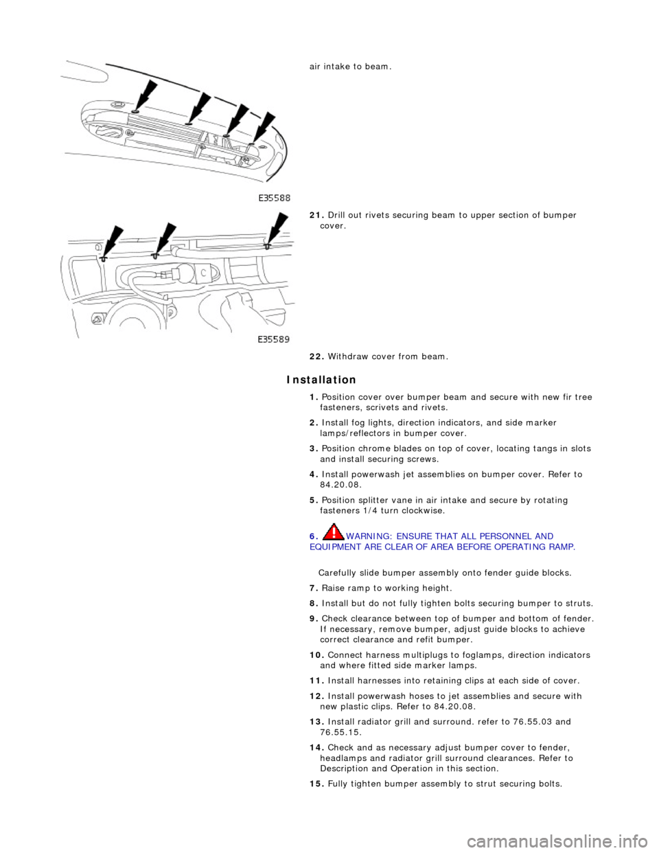
air intake to beam.
21. Drill out rivets securing beam to upper section of bumper
cover.
22. Withdraw cover from beam.
1. Position cover over bumper beam and secure with new fir tree
fasteners, scrivets and rivets.
2. Install fog lights, direction indicators, and side marker
lamps/reflectors in bumper cover.
3. Position chrome blades on top of cover, locating tangs in slots
and install securing screws.
4. Install powerwash jet assemblies on bumper cover. Refer to
84.20.08.
5. Position splitter vane in air intake and secure by rotating
fasteners 1/4 turn clockwise.
6. WARNING: ENSURE THAT ALL PERSONNEL AND
EQUIPMENT ARE CLEAR OF AREA BEFORE OPERATING RAMP.
Carefully slide bumper assembly onto fender guide blocks.
7. Raise ramp to working height.
8. Install but do not fully tighten bo lts securing bumper to struts.
9. Check clearance between top of bumper and bottom of fender.
If necessary, remove bumper, adjust guide blocks to achieve
correct clearance and refit bumper.
10. Connect harness multiplugs to foglamps, direction indicators
and where fitted side marker lamps.
11. Install harnesses into retaining clips at each side of cover.
12. Install powerwash hoses to jet assemblies and secure with
new plastic clips. Refer to 84.20.08.
13. Install radiator grill and su rround. refer to 76.55.03 and
76.55.15.
14. Check and as necessary adjust bumper cover to fender,
headlamps and radiator grill surround clearances. Refer to
Description and Operation in this section.
15. Fully tighten bumper assembly to strut securing bolts.
Page 2417 of 2490
Panels centered between two adjacent panels must have equal gaps on either side. For exceptions to this, refer to the
appropriate specification. Gaps between ad jacent panels or components must not expose harnesses, labels, brackets or
visually poor joint or assembly conditions.
• NOTE: Sliding roof panel clearances are specified without the edge seal installed.
Areas of particular concern are, fuel filler flap, trunk lid to fenders and saddle panels, hood to fenders, grill and headlamps,
sliding roof to main roof panel, door gaps at fenders, B\C posts, roof drip rail an d rocker panel, and bumper cover to fenders
and cross car assemblies
Alignment
Panels must be correctly profiled to maintain cosmetic appearance, and ensure co rrect seating of seals with minimal wind
noise. Areas of particular concern are hood to fenders, trunk lid to fenders and saddle panels, doors to apertures, doors to
fenders and adjacent doors and relationship of the sliding roof panel leading and trailing edges to the main roof panel.
Exterior Fitments
Bezels, trims and lamps must be concentric with apertu res and have equal clearances with adjacent panels.
Areas of particular concern are headlamp to hood, fender and trim panel, exhaust tailpipe trim to bumper cover cut-out,
rear lamp assembly to trunk lid, fender and bumper cover trim, and side feature lines including body side mouldings, fender
to door and door to door.
Exterior Clearances and Alignments-Front