1998 JAGUAR X308 door lock
[x] Cancel search: door lockPage 22 of 2490

Ambient Air Temperature Sensor (82.20. 02)
Cold Ai
r
Bypass Blend Door Actuator (82.20.86)
Defrost Vent/Register Blend Door Actuator (82.20.84)
Footwell Vent/Duct Blend Door Actuator (80.20.20 or 82.20.85)
Instrument Panel Blend Door Actuator (82.20.83)
Remote Climate Control Module LHD (82.20.65)
Remote Climate Control Module RHD (82.20.65)
413: Instrumentation and Warning Sy
stems
413‐00: Instrument Cluster and Panel Illumination
Description and Operation
Instrument Cluster and Panel Illumination
Removal and Installation
Instrument Panel Dimmer Switch (86.65.07)
413‐01: Instrument Cluster
Description and Operation
Instrument Cluster
Diagnosis and Testing
Instrument Cluster
Removal and Installation
Instrument Clust
er (88.20.01)
413‐06: Horn
Description and Operation
Horn
Diagnosis and Testing
Horn
413‐07: Clock
Description and Operation
Clock
Diagnosis and Testing
Clock
Removal and Installation
Clock (88.15.07)
Page 29 of 2490

Parcel Shelf (76.67. 06)
Parcel Shelf
Support (76.67.09)
Passenger Assist Handle (76.58.30)
Rear Door Armrest (76.34.23)
Rear Door Trim Panel Finish Panel (76.47.12)
Rear Door Trim Panel (76.34.04)
Rear Window Blind (76.14.04)
Rear Door Window Control Switch Finish Panel (76.47.34)
Scuff Plate Trim Panel (76.13.81)
Sun Visor (76.10.48)
501‐08: Exterior Trim and Or
namentation
Description and Operation
Exterior Trim
Removal and Installation
A‐Pillar Moulding LH (76.13.19)
A‐Pillar Moulding RH (76.13.20)
Coachlines
Door Moulding (76.43.72)
Front Fender Moulding (76.10.48) (76.43.73)
Luggage Compartment Lid Badges (76.44.03)
Luggage Compartment Lid Moulding (76.43.79)
Radiator Grille (76.
55.03)
Radiator Grille Bezel (76.55.15)
501‐09: Rear View Mirrors
Description and Operation
Rear View Mirrors
Removal and Installation
Auto‐Dimming Interior Mirror (76.10.56)
Exterior Mirror (76.10.52)
Exterior Mirror Cover (76.10.55)
Exterior Mirror Glass (76.10.53)
Exterior Mirror Motor (76.10.57) (76.11.09)
Interior Mirror (76.10.51)
Interior Mirro
r Mounting Block (76.10.62)
Page 32 of 2490

Rear Cup Holder (76.25.27)
Steering Col u
mn
Lower Shroud (76.46.03)
Steering Column Upper Shroud (76.46.02)
501‐14: Handles, Locks, Latches and Entry Systems
Description and Operation
Handles, Locks, Latches and Entry Systems
Removal and Installation
Exterior Driver Door Handle (76.58.07)
Driver Door Latch (76.37.74)
Glove Compartment Lid Ha
ndle (76.52.08)
Glove Compartment Lid Lock Cylinder (76.52.23)
Luggage Compartment Lid Latch (76.19.25)
Luggage Compartment Lid Latch Actuator (76.19.25)
Luggage Compartment Lid Release Switch (86.25.56)
Luggage Compartment Lid Warning Indicator Switch (86.65.93)
Exterior Passenger Door Handle (76.58.08)
Passenger Door Latch (76.37.75)
Exterior Rear Door Handle (76.58.02)
Rear Door Latch (76.37.09)
501‐16: Wipers and Washers
Descriptio
n and Operation
Wipers and Washers
Removal and Installation
Headlamp Washer Jet (84.20.08)
Headlamp Washer Pump (84.20.21)
Rain Sensor (84.12.10) (86.56.62)
Windshield Washer Pump (84.10.21)
Windshield Washer Reservoir (84.10.01) (84.10.03)
Windshield Wiper Motor (84.15.13)
Windshield Wiper/
Washer Switch (86.65.42)
Wiper Pivot Arm (84.15.03)
Page 49 of 2490

Identification
Codes -
Identification Codes
Descr
iption and Operation
En
gine Number
The en
gine number (10 digits) is stamped on a raised pad on th
e front of the engine block near the thermostat housing. The
piston grade reference (8 digits) is also shown.
Automatic Transmission
Number
The
serial number of the transmission unit is displayed on
a metal or bar code label attached to the LH side of the
transmission casing.
Veh
icle Identification
Dependent
upon market, the VIN and other info
rmation is displayed on a label located ei ther on the rear edge of the LH front
door or on the body front upper crossmember. For certain mark ets, the VIN appears on a bar code label referred to as the
Certification Label and additionally carries the month and year of manufacture, vehicle weight data and paint and trim codes.
The VIN is also displayed on a plate visible through the windshie ld. It is essential that the vehicle identification number (VIN)
is quoted when ordering parts, and in all associated correspondence.
ItemDe
scription
GVW
R
G
ross Vehicle Weight Rating
GAW
R F
Gros
s Front Axle Weight Rating
GAW
R R
Gros
s Rear Axle Weight Rating
Pai
nt
Pai
nt Code
TrimTrim
Code
Page 717 of 2490

25. Reconnect the air flow meter multi-plug.
26. fit a new strap to secures the vacuum pipe to the induction
elbow.
27. Connect the breather pipe to the A-Bank camshaft cover.
1. Fit a new O-ring seal to the breather pipe.
2. Reconnect the breather pipe to the stub pipe.
28. Carefully refit the engine covers, taking care not to damage
the plastic fixings or the rubber inserts.
29. Connect the battery ground cabl e. Refit the battery cover.
Reset the clock and the radio information.
30. Check for leaks and that all pi pes are securely connected.
Remove the protection sheets, close the engine compartment,
luggage compartment and doors.
Page 728 of 2490

2. Reconnect the breather pipe to the stub pipe.
21. Carefully refit the engine covers, taking care not to damage
the plastic fixings or the rubber inserts.
22. Connect the battery ground cabl e. Refit the battery cover.
Reset the clock and the radio information.
23. Check for leaks and that all pi pes are securely connected.
Remove the protection sheets, close the engine compartment,
luggage compartment and doors.
Page 1693 of 2490

Filler Cap and P
ipe
The fuel
filler cap with bayonet-type fixi
ng is located beneath a remote-release sp ring-latched lid on the rear saddle panel
on the left-hand-side of the vehicle.
Fuel Pum
p
The fu
el pump(s) is energized by an ECM co
ntrolled relay. Fuel is drawn by this pu mp and supplied to the fuel injectors via
the fuel line, filter and fuel rails.
Servicing of the fuel pump re quires fuel tank removal.
Ev
aporative Loss Flange Assembly
The evaporative-loss flan
ge asse
mbly is mounted centrally on top of the tank. The flange assembly consists of a removeable
steel cap which mounts the evaporative emissions system vapor outlet valves and, if applicable, a pressure sensor. The
external electrical supply to th e fuel pump(s) is also made via a connector on the flange.
The flange assembly is fixed to the tank by a locking ring which is turned usin g special tool JD-174. A seal is fitted between
the flange assembly and the tank. Three di fferent flange assemblies are applicable according to the evaporative emission
system fitted to the vehicle. The fl ange size and fixing are identical fo r the three systems, as described.
Removal of the evaporative flange assembly is necessary to gain access to th e fuel pump(s) and other internal components.
To remove the evaporative fl ange assembly the fuel tank must first be removed.
The evaporative flange variant assemblies are described, together with service information, in Section 303-13.
Fuel R
eturn
Excess fuel
is directed back to
the fuel tank via a return line.
Fuel Pum
p Relay
The
fuel pump relay,
under control of the ECM, switches power to the fuel pump motor.
I
nertia Fuel Shutoff (IFS) Switch
The IF
S switch is located in the right-hand
side footwell behind the footboard carpet . When activated the switch isolates the
ignition system and fuel pump, releases any locked doors and disables unnecessary electrical systems. The system can be
reset by pressing down the flexible cover on the top of the switch.
• NOTE: The doors will not unlock if the IFS switch is tripped when the ignition switch is in position '0'.
Page 1777 of 2490

Air Distribution and Filtering - Center Registers
Removal and Installation
Removal
Installation
1.
Remove battery cover and disconnect ground cable from battery
terminal. Refer to 86.15.19.
2. Remove passenger airbag deployment door for access. Refer to
Section 501-20.
3. Remove major gauge module veneer panel for access. Refer to
76.47.24.
4. Carefully withdraw fascia centre veneer panel.
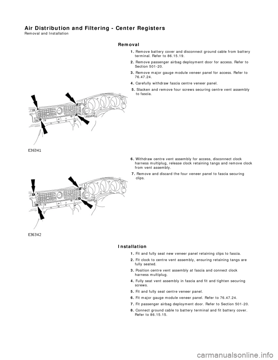
5. Slacken and remove four screws securing centre vent assembly
to fascia.
6. Withdraw centre vent assembly for access, disconnect clock
harness multiplug, release clock retaining tangs and remove clock
from vent assembly.
7. Remove and discard the four veneer panel to fascia securing
clips.
1. Fit and fully seat new veneer panel retaining clips to fascia.
2. Fit clock to centre vent assemb ly, ensuring retaining tangs are
fully seated.
3. Position centre vent assembly at fascia and connect clock
harness multiplug.
4. Fully seat vent assembly in fascia and fit and tighten securing
screws.
5. Fit and fully seat centre veneer panel.
6. Fit major gauge module veneer panel. Refer to 76.47.24.
7. Fit passenger airbag deployment door. Refer to Section 501-20.
8. Connect ground cable to battery terminal and fit battery cover.
Refer to 86.15.15.