1998 JAGUAR X308 exhaust gas recirculation
[x] Cancel search: exhaust gas recirculationPage 14 of 2490

303‐07: En gine Ignition
Specification
Diagnosis and Testing
Engine Ignition
Diagnosis and Testing
Engine Ignition
Inspection and Verification
Driver Information Chart
Default mode Definitions
Diagnostic Trouble Code (DTC) index
Pinpoint Tests
Removal and Installation
Ignition Coil ‐On ‐Plug LH (18.20.44)
Ignition Coil ‐On ‐Plug RH (18.20.43)
Ignition Module (18.20.30)
Spark Plugs (18.20.02)
303‐08: En
gine Emission Control
Specification
Diagnosis and Testing
Engine Emission Control
Inspection and Verification
Diagnostic Trouble Code (DTC) Index
Pinpoint Tests
Removal and Installation
Exhaust Gas Recirculation (EGR) Valve (17.45.01)
Exhaust Manifold to Exhaust Gas Recirculation (E
GR) Valve Tube (17.45.11)
303‐12: Intake Air Distribution and Filtering
Removal and Installation
Air Cleaner (19.10.05)
Air Cleaner Element (19.10.08)
Charge Air Cooler LH (18.50.19)
Charge Air Cooler RH (18.50.18)
Charge Air Cooler Gasket LH (18.50.22)
Charge Air Cooler Gasket RH (18.50.21)
Supercharger (18.50.
15)
Page 44 of 2490

Electrically Programmable
R
ead-Only memory
EPROM
Ele
c
tronic Secondary Air
Injection
EAIRA p
ump-driven system for providing seco
ndary air using an electric air pump
Engine C
ontrol Module
ECM
End of dashEODR
e
ferring to a vehicle fascia, eg EOD air vent
Engine
C
oolant Level
ECL
Engine
C
oolant
Temperature
ECT
ECT Sen s
or
ECTSTherm
i
stor which provides engine coolant temperature signal to the ECM to
trigger enrichment circuits which increase injector 'on' time for cold start and
warm-up
Engine s
peed
RP
M
Environ m
ental Protection
Agency
EPA
Evaporative EmissionEVAPSy stem designed to prevent fu
el vapor from escaping into the atmosphere.
Typically includes a charcoal filled canister to absorb fuel vapor
Evaporative Emission
Control ValveEVAPP
Exhaust G
as Recirculation
EGRSys
t
em which reduces NOx emissions by adding exhaust gases to the
incoming fuel/air charge
Exhaus t G
as Recirculation
Solenoid Vacuum Valve
EGRS
Exhaus t G
as Recirculation
Temperature Sensor
EGRT Sen s
or
Exhaus
t G
as Recirculation
Valve
EGRV
F
F a
n Control
FCEngine
cooling fan control
F
e
deral Motor Vehicle
Safety Standard (US)
FMV S
S
Fi
gur
e
Fi
g.Illustrati
on reference
Flash
E
lectrically Erasable
Programmable Read-Only
Memory
FEE PR
OM
Flash
E
rasable
Programmable Read-Only
Memory
FEP R
OM
Flywhee
l
Sensor
CKFSSens
or moun
ted so as to be
triggered by each flywheel ring gear tooth to give
an engine speed signal
Fue l
Injectors
FISol
e
noid operated devices that spray a metered quantity of fuel into the inlet
ports
F u
el Pressure Regulator
Control
FP RCControls fuel pressure regu l
ator; used primarily to
give extra fuel at cold
start-up
Fue l
Pump
FP
Fue
l
Pump Monitor
FP
MMonitors operation of fuel pump
Fue l
Pump Relay
FP
R
Fu
el rich/lean
Q
u
alitative evaluation
of air/fuel ratio based on a ratio known as
stoichiometry, or 14.7:1 (Lambda)
F u
ll Scale Deflection
FSDTh
e
maximum indication point on
an analogue meter or gauge
G
Gene
rator
GENRot
a
ting machine which converts mechanical energy into electrical energy
G
r
amme centimeter
gcm
Gramm
e
(force)
gf
Gramm
e
(mass)
g
GroundGNDEle
c
trical conductor used
as a common return for an electrical circuit or
circuits, and with a relative zero potential
H
Hard f a
ult
A
fau
lt currently present in the system
HeadlampHL
Heat
ed Oxygen
Sensor
HO2SElectrically
h
eated oxygen sensor which induces fueling corrections
Hertz (frequency)HzFrequ
e
ncy, one cycle per second
High
Moun
ted Stoplamp
HMSL
Page 529 of 2490
Thi
s sensor uses a piezo-electric sensing element to detect kn
ock which may occur under acceleration at critical conditions.
Should detonation be present the ECM will retard ignition timing of individual cylinders.
Exhaust G
as Recirculation
The EGR
valve (where fitted) reduces NOx
emissions by recirculating a portion of the exhaust gases back into the inlet
manifold.
Heated Oxyg
en Sensors
The h
eated oxygen sensors, one per bank, are situated upstream of the catalysts. Integral
to the sensors are heaters
(under ECM control) which allow the sensor s to reach their operating temperature as soon as possible after engine start. A
comparison between the level of oxygen in the exhaust gas to that in the atmosphere produces an output signal. This signal
is used by the engine closed loop fuel strategy to make fuelling corrections and so control overall emission levels.
Oxygen Sensors
Thes
e sensors, one per bank, are situated downstream of the
catalyst. The comparison of upstream and downstream signals
allows determination of cata lyst conversion efficiency.
Knock Sensor
Page 1095 of 2490
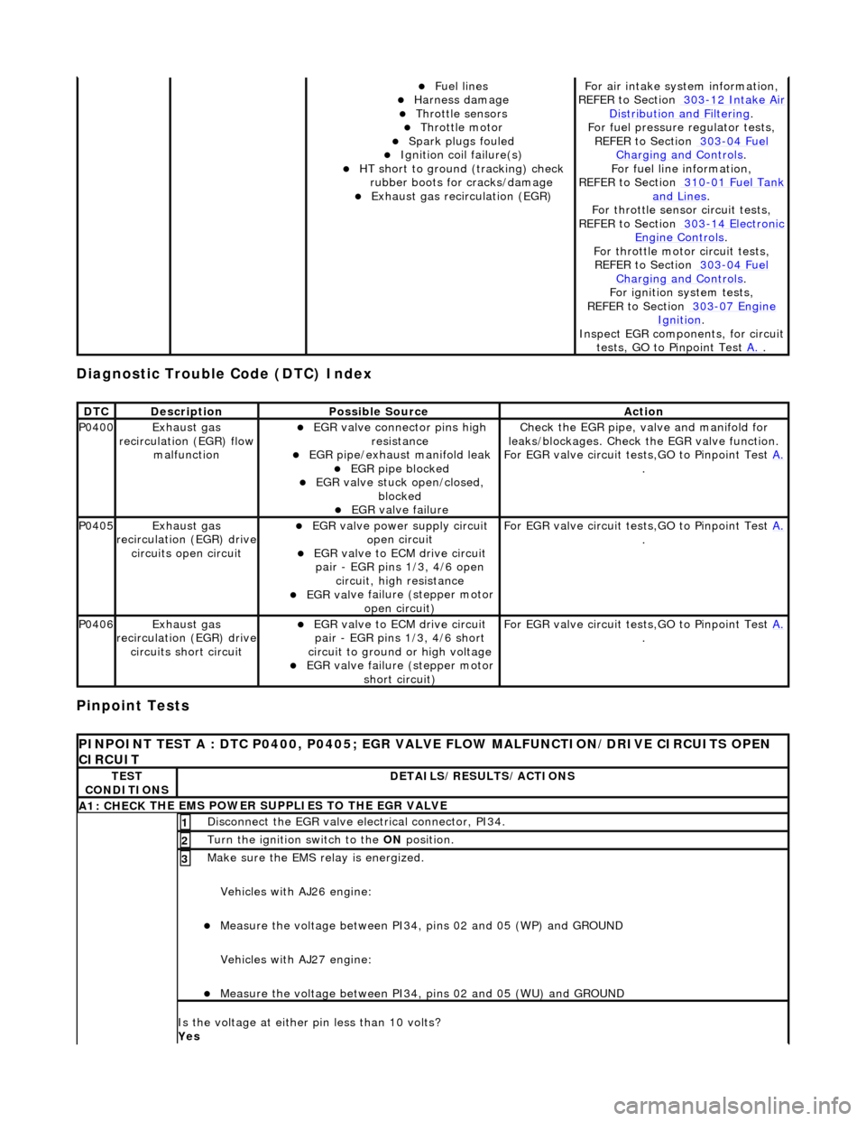
Diagnostic Trouble Code (D
TC) Index
Pinpoint Tests
Fue
l lines
Harness damage
Throttl
e sensors
Throttl
e motor
Spark plugs
fouled
Ignition coil
failure(s)
HT sho
rt to ground (tracking) check
rubber boots for cracks/damage
Exhaus
t gas recirculation (EGR)
F
or air intake syst
em information,
REFER to Section 303
-12
Intake Air
Distribu
tion and Filtering
.
F
or fuel pressure
regulator tests,
REF
ER to Section 303
-04
Fuel
Charging and Con
trols
.
F
or fuel line information,
REFER to Section 310
-01
Fuel Tank
and Lines.
F
or throttle sensor
circuit tests,
REFER to Section 303
-14
Electronic
Engine
Controls
.
Fo
r throttle motor
circuit tests,
REFER to Section 303
-04
Fuel
Charging and Con
trols
.
For ign
ition system tests,
REFER to Section 303
-07
Engine
Ignition.
Inspe
ct EGR components, for circuit
tests, GO to Pinpoint Test A.
.
DT
C
De
scription
Possib
le Source
Acti
on
P0400Exhaus
t gas
recirculation (EGR) flow malfunction
EGR
valve connector pins high
resistance
EGR pipe/exhaust manifold leak EGR pipe block
ed
EGR val
ve stuck open/closed,
blocked
EGR
valve failure
Check the EGR pi
pe, valve and manifold for
leaks/blockages. Check the EGR valve function.
For EGR valve circuit tests,GO to Pinpoint Test A.
.
P0405Exhaus
t gas
recirculation (EGR) drive
circuits open circuit
EGR valve power supply circuit o
pen circuit
EGR valve t
o ECM drive circuit
pair - EGR pins 1/3, 4/6 open circuit, high resistance
EGR val
ve failure (stepper motor
open circuit)
F
or EGR valve circuit tests,GO to Pinpoint Test
A.
.
P0406Exhaus
t gas
recirculation (EGR) drive
circuits short circuit
EGR valve t
o ECM drive circuit
pair - EGR pins 1/3, 4/6 short
circuit to ground or high voltage
EGR val
ve failure (stepper motor
short circuit)
F
or EGR valve circuit tests,GO to Pinpoint Test
A.
.
P
INPOINT TEST A : DTC P0400, P0405; EGR VALV
E FLOW MALFUNCTION/DRIVE CIRCUITS OPEN
CIRCUIT
TE
ST
CONDITIONS
D
ETAILS/RESULTS/ACTIONS
A1: CHECK
THE EMS POWER SU
PPLIES TO THE EGR VALVE
D
isconnect the EGR valve electrical connector, PI34.
1
Turn the ignition swi
tch to the ON
position.
2
Make sure the EMS re lay i
s energized.
Vehicles with AJ26 engine:
Me
asure the voltage between PI34, pins 02 and 05 (WP) and GROUND
Vehicles with AJ27 engine:
Me
asure the voltage between PI34, pins 02 and 05 (WU) and GROUND
3
Is th
e voltage at either pin less than 10 volts?
Yes
Page 1096 of 2490
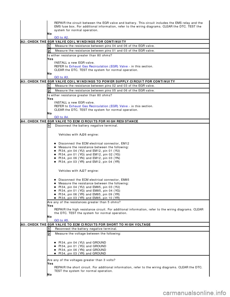
RE
PAIR the circuit between the EGR valve and battery. This circuit includes the EMS relay and the
EMS fuse box. For additional info rmation, refer to the wiring diagrams. CLEAR the DTC. TEST the
system for normal operation.
No GO to A2
.
A2: CHECK THE EGR VALVE COIL WIND
INGS FOR CONTINUITY
Meas
ure t
he resistance between pins 04 and 06 of the EGR valve.
1
Meas
ure t
he resistance between pins 01 and 03 of the EGR valve.
2
Is either resi
stance
greater
than 80 ohms?
Yes INSTALL a new EGR valve.
REFER to Exhaust Gas Recirculation (EGR) Valve
- in thi
s section.
CLEAR the DTC. TEST the syst em for normal operation.
No GO to A3
.
A3: CHECK THE EGR VALVE COIL WINDINGS TO
POWER SUPPLY CIRCUIT FOR CONTINUITY
Meas
ure t
he resistance between pins 02 and 03 of the EGR valve.
1
Meas
ure t
he resistance between pins 05 and 06 of the EGR valve.
2
Is either resi
stance greater
than 80 ohms?
Yes INSTALL a new EGR valve.
REFER to Exhaust Gas Recirculation (EGR) Valve
- in thi
s section.
CLEAR the DTC. TEST the syst em for normal operation.
No GO to A4
.
A4: CHECK THE EGR VALVE T
O ECM
CIRCUITS FOR HIGH RESISTANCE
Disc
onnect the battery negative terminal.
Vehicles with AJ26 engine:
D i
sconnect the ECM electrical connector, EM12
Meas
ure t
he resistance between the following:
PI34, pin
0
4 (YU) and EM12, pin 01 (YU)
PI34,
pi
n 01 (YG) and EM12, pin 02 (YG)
PI34, pin
0
6 (YN) and EM12, pin 03 (YN)
PI34,
pi
n 03 (YR) and EM12, pin 04 (YR)
Vehicles with AJ27 engine:
D i
sconnect the ECM electrical connector, EM85
Meas
ure t
he resistance between the following:
PI34, pin
0
4 (YU) and EM85, pin 03 (YU)
PI34, pi
n 01 (YG) and EM85, pin 04 (YG)
PI34, pi
n 06 (YR) and EM85, pin 09 (YR)
PI34, pi
n 03 (YR) and EM85, pin 10 (YR)
1
Are an
y of the resistances greater than 5 ohms?
Yes REPAIR the high resistance circui t. For additional information, refer to the wiring diagrams. CLEAR
the DTC. TEST the system for normal operation.
No GO to A5
.
A5: CHECK THE EGR VALVE T
O ECM CIRCUITS FOR SHORT TO HIGH VOLTAGE
R
e
connect the battery negative terminal.
1
Meas
ure t
he voltage between the following:
PI34, pin
0
4 (YU) and GROUND
PI34, pin
0
1 (YG) and GROUND
PI34, pin
0
6 (YN) and GROUND
PI34, pin
0
3 (YR) and GROUND
2
Are any of th
e volt
ages greater than 3 volts?
Yes REPAIR the short circuit. For addi tional information, refer to the wiring diagrams. CLEAR the DTC.
TEST the system for normal operation.
No
Page 1098 of 2490
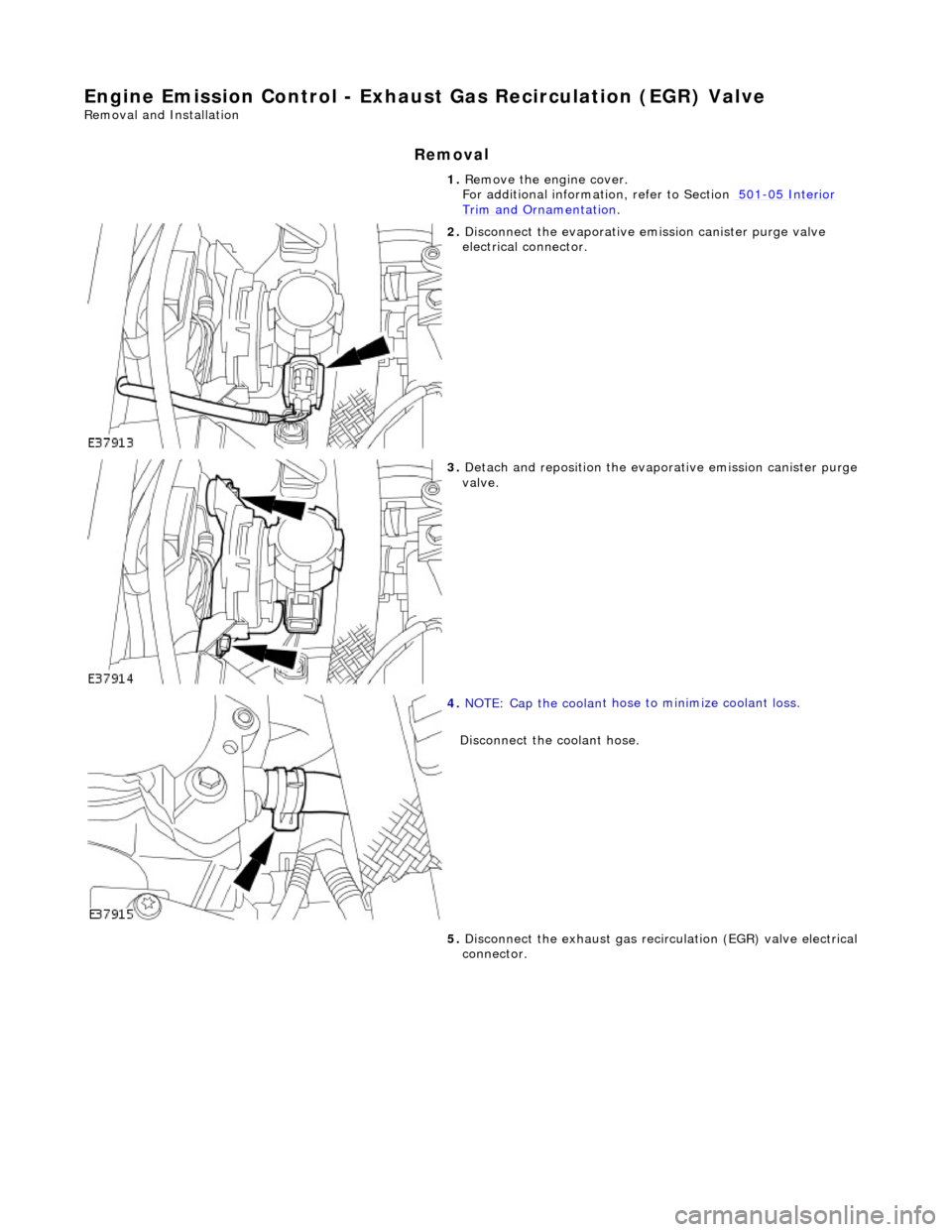
Engine Emission
Control - Exhaus
t Gas Recirculation (EGR) Valve
Remo
val and Installation
Remov
a
l
1.
Re
move the engine cover.
For additional informat ion, refer to Section 501
-05
Interior
Trim and Ornamen
t
ation
.
2. Disc
onnect the evaporative emission canister purge valve
electrical connector.
3. Detac
h and reposition the evaporative emission canister purge
valve.
4. NOTE : Cap the coolan
t hose
to minimize coolant loss.
Disconnect the coolant hose.
5. Disconnect the exhaust gas recirc ulation (EGR) valve electrical
connector.
Page 1103 of 2490
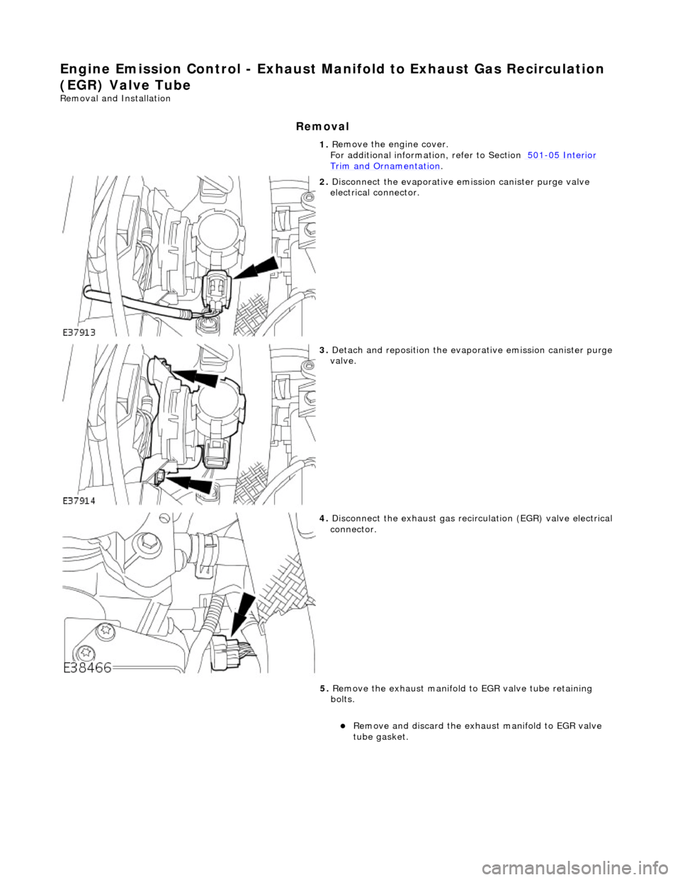
E
ngine Emission Control - Exhaust Ma
nifold to Exhaust Gas Recirculation
(EGR) Valve Tube
Re
moval and Installation
Remov
al
1.
R
emove the engine cover.
For additional informat ion, refer to Section 501
-0
5 Interior
Trim and Ornamen
tation
.
2. Di
sconnect the evaporative emission canister purge valve
electrical connector.
3. De
tach and reposition the evaporative emission canister purge
valve.
4. Di
sconnect the exhaust gas recirc
ulation (EGR) valve electrical
connector.
5. Remove the exhaust manifold to EGR valve tube retaining
bolts.
Remove an
d discard the exhaust manifold to EGR valve
tube gasket.
Page 1134 of 2490
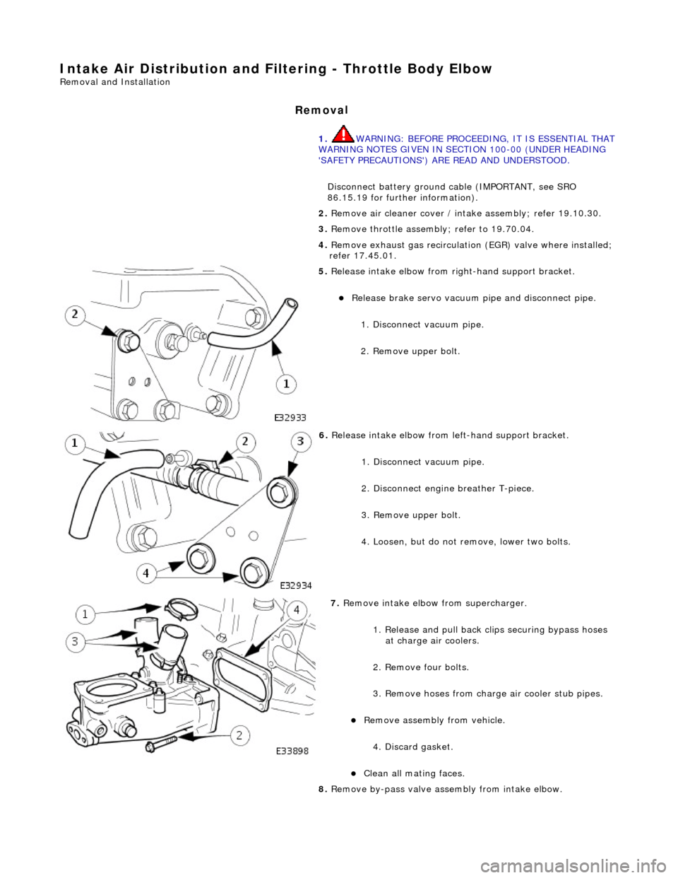
Intake Air Distribution and Filtering - Thrott
le Body Elbow
Re
mo
val and Installation
Remov
a
l
1.
WARNING: B E
FORE PROCEEDING, IT IS ESSENTIAL THAT
WARNING NOTES GIVEN IN SECTION 100-00 (UNDER HEADING
'SAFETY PRECAUTIONS') AR E READ AND UNDERSTOOD.
Disconnect battery ground cable (IMPORTANT, see SRO
86.15.19 for further information).
2. Re
move air cleaner cover / inta
ke assembly; refer 19.10.30.
3. Remove throttle assemb ly; refer to 19.70.04.
4. Remove exhaust gas recirculation (EGR) valve where installed;
refer 17.45.01.
5. Re
lease intake elbow from right-hand support bracket.
Re
lea
se brake servo vacuum pi
pe and disconnect pipe.
1. Disconnect vacuum pipe.
2. Remove upper bolt.
6. Relea
se intake elbow from le
ft-hand support bracket.
1. Disconnect vacuum pipe.
2. Disconnect engine breather T-piece.
3. Remove upper bolt.
4. Loosen, but do not remove, lower two bolts.
7. Re
move intake elbow from supercharger.
1. Release and pull back cl ips securing bypass hoses
at charge air coolers.
2. Remove four bolts.
3. Remove hoses from charge air cooler stub pipes.
Re move as
sembly from vehicle.
4. Discard gasket.
Cle a
n all mating faces.
8. Remove by-pass valve assembly from intake elbow.