Page 1219 of 2490

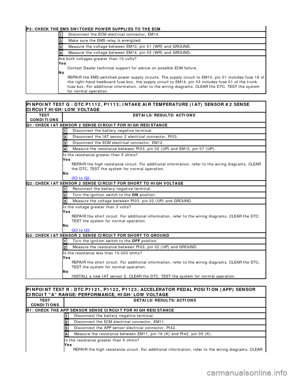
P3: CHECK
THE EMS SWITCHED
POWER SUPPLIES TO THE ECM
D
isconnect the ECM electrical connector, EM14.
1
Make sure the EMS re
lay i
s energized.
2
Meas
ure the voltage between EM10, pin 01 (WR) and GROUND.
3
Meas
ure the voltage between EM14, pin 03 (WR) and GROUND.
4
Are both
voltages greater than 10 volts?
Yes Contact Dealer technical support for advice on possible ECM failure.
No REPAIR the EMS switched power supply circuits. The su pply circuit to EM10, pin 01 includes fuse 18 of
the right-hand heelboard fuse box, the supply circuit to EM14, pin 03 includes fuse 01 of the trunk
fuse box. For additional information, refer to th e wiring diagrams. CLEAR the DTC. TEST the system
for normal operation.
PI
NPOINT TEST Q : DTC P1112, P1113; INTAKE
AIR TEMPERATURE (IAT) SENSOR #2 SENSE
CIRCUIT HIGH/LOW VOLTAGE
TE
ST
CONDITIONS
D
ETAILS/RESULTS/ACTIONS
Q1:
CHECK IAT SENSOR 2 SENSE CIRCUIT FOR HIGH RESISTANCE
Di
sconnect the battery negative terminal.
1
Di
sconnect the IAT sensor 2 electrical connector, PI03.
2
D
isconnect the ECM electrical connector, EM12.
3
Me
asure the resistance between PI03, pin 02 (UP) and EM12, pin 07 (UP).
4
Is th
e resistance greater than 5 ohms?
Yes REPAIR the high resistance circui t. For additional information, refer to the wiring diagrams. CLEAR
the DTC. TEST the system for normal operation.
No GO to Q2
.
Q2: CH
ECK IAT SENSOR 2 SENSE CIRC
UIT FOR SHORT TO HIGH VOLTAGE
R
econnect the battery negative terminal.
1
Turn the ignition swi
tch to the ON
position.
2
Measure the
voltage between PI
03, pin 02 (UP) and GROUND.
3
Is th
e voltage greater than 3 volts?
Yes REPAIR the short circuit. For addi tional information, refer to the wiring diagrams. CLEAR the DTC.
TEST the system for normal operation.
No GO to Q3
.
Q3:
CHECK IAT SENSOR 2 SENSE CIRCUIT FOR SHORT TO GROUND
Turn the ignition swi
tch to the OFF
position.
1
Meas
ure the resistance between PI03, pin 02 (UP) and GROUND.
2
Is
the resistance less than 10,000 ohms?
Yes REPAIR the short circuit. For addi tional information, refer to the wiring diagrams. CLEAR the DTC.
TEST the system for normal operation.
No INSTALL a new IAT sensor 2. CLEAR the DTC. TEST the system for normal operation.
P
INPOINT TEST R : DTC P1121, P1122, P1123;
ACCELERATOR PEDAL POSITION (APP) SENSOR
CIRCUIT "A" RANGE/PERFORMANCE, HIGH/LOW VOLTAGE
TE
ST
CONDITIONS
D
ETAILS/RESULTS/ACTIONS
R1: CHECK THE APP
SENSOR SENSE CIRCUIT FOR HIGH RESISTANCE
Di
sconnect the battery negative terminal.
1
D
isconnect the ECM electrical connector, EM11.
2
Di
sconnect the APP sensor electrical connector, PI42.
3
Meas
ure the resistance between EM11, pin 16 (K) and PI42, pin 05 (K).
4
Is th
e resistance greater than 5 ohms?
Yes REPAIR the high resistance circui t. For additional information, refer to the wiring diagrams. CLEAR
Page 1256 of 2490
El
ectronic Engine Controls -
Mass Air Flow (MAF) Sensor
Remo
val and Installation
Remov
a
l
1.
Disc onne
ct battery ground cable (IMPORTANT, see SRO
86.15.19 for further information).
2. Disc
onnect connector from MAF sensor.
3. Re
move bolts securing MAF sensor to air cleaner.
4. Re
move air cleaner cover.
Re
lea
se clips.
5. Re
lease band clip - trunking to MAF sensor and remove
assembly.
Di sc
ard sensor seals
Page 1692 of 2490

Fuel Tank and Lines - Fuel Tank and Li
nes
Description an
d Operation
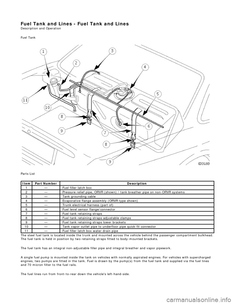
Fuel Tank
Parts List
The steel fuel tank is located inside the trunk and mounted across the vehicle behind the passenger compartment bulkhead.
The fuel tank is held in posi tion by two retaining straps fi tted to body-mounted brackets.
The fuel tank has an integral non-adjustable fill er pipe and integral breather and vapor pipework.
A single fuel pump is mounted inside the tank on vehicles with normally aspirated engines. For vehicles with supercharged
engines, two pumps are fitted in the tank. Fuel is drawn by the pump(s) from the fuel tank and supplied via the fuel lines
and 70 micron filter to the fuel rails.
The fuel lines run from front-to-rear down the vehicle's left-hand-side.
Ite
m
Part
Number
Descr
iption
1—Fu
el filler latch box
2—Pressure reli
ef pipe, ORVR
(shown) / tank breather pipe on non-ORVR systems
3—Tank grounding
cable
4—Evaporative flan
ge assembly
(ORVR type shown)
5—Trunk elec
trical harne
ss (part of)
6—Fue
l
level sensor
flange/connector
7—Fu
el tank retaining straps
8—F
u
el tank retaining stra
ps adjustable clamps
9—Fu
el tank retaining straps lower brackets
10—Tank vapor outlet pipe to un
derflo
or pipe quick-fit connector
11—F
u
el filler latch bo
x water drain pipe
Page 1699 of 2490
Conne
ct the scan tool
1
Have the DTC(s) and fr
eeze
frame data been recorded?
Yes GO to A2
A2
: CHECK FUSE
•
NOTE: See further steps for poss
ible cause of fuse failure.
Chec
k fuse F7 integrity (located in the trunk).
1
OK
?
Yes GO to A3
No Renew fuse and test the syst em for normal operation.
A3:
CHECK SHORT TO SUPPLY
Page 1713 of 2490
Conne
ct the scan tool
1
Have the DTC(s) and fr
eeze
frame data been recorded?
Yes GO to B2
B2
: CHECK FUSE
•
NOTE: See further steps for poss
ible cause of fuse failure.
Chec
k fuse 15 integrity (located in the trunk)
1
OK
?
Yes GO to B3
No Renew fuse and test the syst em for normal operation.
B3:
CHECK SHORT TO SUPPLY
Page 1732 of 2490
Fu
el Tank and Lines - Fuel Level Sensor
Remov
a
l and Installation
Removal
Ins
tallation
1.
WA
RNING: BEFORE PROCEEDING, IT IS ESSENTIAL THAT THE
WARNING NOTES GIVEN IN SECTIO N 100-00 (UNDER THE HEADING
'SAFETY PRECAUTIONS') ARE READ AND UNDERSTOOD.
Remove the battery. For additional information, refer to Section 414
-01
Battery, Mounting and Cables
.
2.
Drain
the fuel tank using a suitable suction pump/tanker. If the On-
board Refueling Vapour Recovery (ORVR) system is fitted, refer to
Section 310
-00 Fu
el System
- Gen
e
ral Information
.
3. Remov
e the trunk front liner. For additional information, refer to
Section 501
-05 Interior Trim
and Ornamentation
.
4. D
isconnect the harness co
nnections to the sensor.
5. U
sing special tool 18G 1001, remo
ve the sensor retaining ring.
6.
Remov
e the sensor assembly and discard the seal.
1. Fitting a new level sensor is the reverse of the removal procedure,
noting that a new seal must be fitted.
Page 1734 of 2490

Fuel Tank and Lines - Fuel Tank
Re
mo
val and Installation
Remov
a
l
•
NO
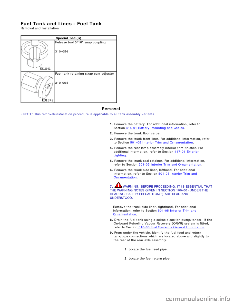
TE: This removal/installation procedure is applicable to all tank assembly variants.
S
p
ecial Tool(s)
R
e
lease tool 5/16" snap coupling
310-054
F u
el tank retaining strap cam adjuster
310-094
1. Remove the battery. For additi onal information, refer to
Section 414
-01
Battery, Mounting and Cables
.
2. Re
move the trunk floor carpet.
3. Remove the trunk front liner. Fo r additional information, refer
to Section 501
-05
Interior Trim and Ornamentation
.
4. Re
move the rear lamp assembly interior trim finisher. For
additional information, refer to Section 417
-01
Exterior
Ligh
ting.
5. Re
move the trunk seal retainer
. For additional information,
refer to Section 501
-0 5
Interior Trim and Ornamentation
.
6. Re
move the trunk side liner, lefthand. For additional
information, refer to Section 501
-05
Interior Trim and
Or
n
amentation
.
7. WARNING: B E
FORE PROCEEDING, IT IS ESSENTIAL THAT
THE WARNING NOTES GIVEN IN SECTION 100-00 (UNDER THE
HEADING 'SAFETY PRECAUTIONS') ARE READ AND
UNDERSTOOD.
Remove the trunk side liner, righthand. For additional
information, refer to Section 501
-05
Interior Trim and
Or
n
amentation
.
8.
Drain th e fue
l tank using a suitab
le suction pump/tanker. If the
On-board Refueling Vapour Recove ry (ORVR) system is fitted,
refer to Section 310
-00 Fu
el System
- General
Information
.
9. Fr
om under the vehicle, identify the fuel feed and return
tank/pipe connections which are located above and slightly to
the rear of the rear axle assembly.
1. Locate the fuel feed pipe.
2. Locate the fuel return pipe.
Page 1735 of 2490

10
.
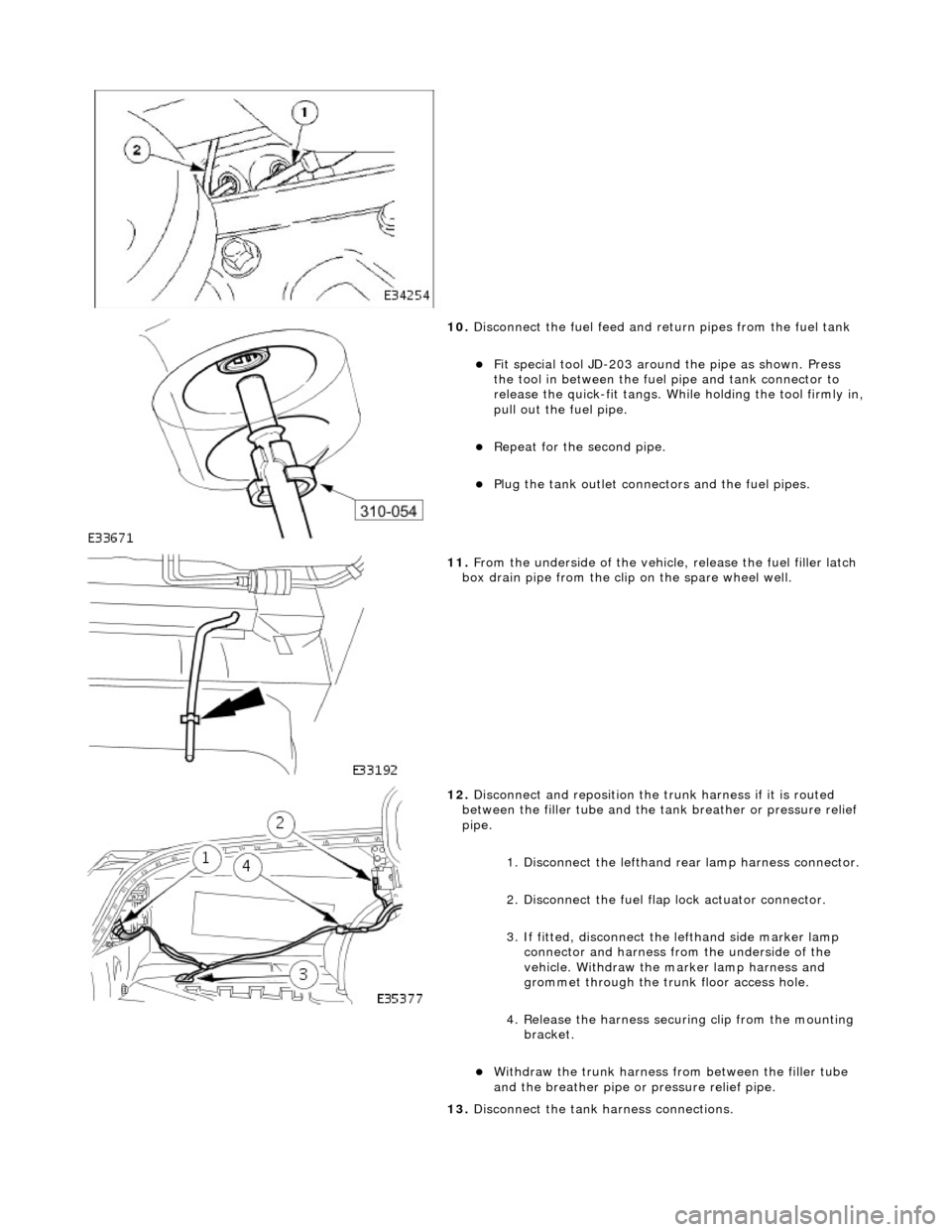
Disconnect the fuel feed and return pipes from the fuel tank
F
it special tool JD-203 around
the pipe as shown. Press
the tool in between the fuel pipe and tank connector to
release the quick-fit tangs. While holding the tool firmly in,
pull out the fuel pipe.
Repeat
for the second pipe.
Plu
g the tank outlet connectors and the fuel pipes.
11
.
From the underside of the vehicl e, release the fuel filler latch
box drain pipe from the clip on the spare wheel well.
12
.
Disconnect and reposition the tr unk harness if it is routed
between the filler tube and the ta nk breather or pressure relief
pipe.
1. Disconnect the lefthand re ar lamp harness connector.
2. Disconnect the fuel flap lock actuator connector.
3. If fitted, disconnect the lefthand side marker lamp
connector and harness fro m the underside of the
vehicle. Withdraw the marker lamp harness and
grommet through the trunk floor access hole.
4. Release the harness securi ng clip from the mounting
bracket.
Wi
thdraw the trunk harness from between the filler tube
and the breather pipe or pressure relief pipe.
13. Disconnect the tank harness connections.