Page 1737 of 2490
I
nstallation
18
.
On non-ORVR vehicles, disconnect the trunk lid lefthand strut
rear pivot.
Pl
ace a suitable support under
trunk lid or tie to exterior
mirror.
1. Using a screwdriver, release clip at rear end of strut,
withdraw end from trunk lid pivot and lower strut.
19
.
Disconnect the tank ground cable from the vehicle body.
20. Remove the tank from the vehicle.
21. Drain any remaining fuel from the tank.
1. Fit the fuel tank assembly.
2. Re
-connect the tank ground cable to the vehicle.
Tigh
ten to 12 Nm.
3. On non-ORVR fuel tanks, positi on the trunk lid lefthand strut
between the filler tube and the breather pipe.
Page 1738 of 2490
4. Full
y seat the tank into positi
on, ensuring that no harness
wiring is trapped.
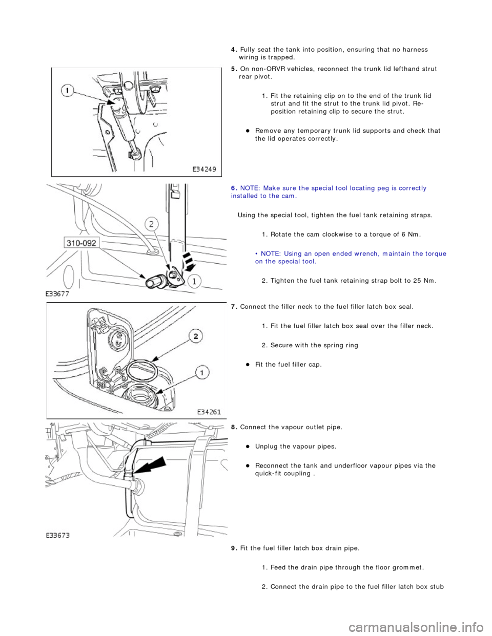
5. On non-
ORVR vehicles, reconnec
t the trunk lid lefthand strut
rear pivot.
1. Fit the retaining clip on to the end of the trunk lid strut and fit the strut to the trunk lid pivot. Re-
position retaining clip to secure the strut.
Re
move any temporary trunk lid supports and check that
the lid operates correctly.
6. NOTE
: Make sure the special tool locating peg is correctly
installed to the cam.
Using the special tool, tighten the fuel tank retaining straps.
1. Rotate the cam clockwise to a torque of 6 Nm.
• NOTE: Using an open ended wrench, maintain the torque
on the special tool.
2. Tighten the fuel tank reta ining strap bolt to 25 Nm.
7. Connect the fi
ller neck to the fuel filler latch box seal.
1. Fit the fuel filler latch box seal over the filler neck.
2. Secure with the spring ring
F i
t the fuel filler cap.
8. Connect the vapour outlet pip
e.
Unplug the v
a
pour pipes.
Reconn
ect th
e tank and underfloor vapour pipes via the
quick-fit coupling .
9. Fit the fuel filler latch box drain pipe.
1. Feed the drain pipe th rough the floor grommet.
2. Connect the drain pipe to the fuel filler latch box stub
Page 1739 of 2490
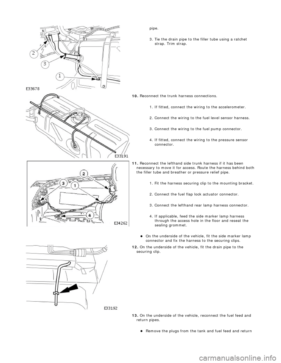
pipe.
3
. Tie the drain pipe to th
e filler tube using a ratchet
strap. Trim strap.
10
.
Reconnect the trunk harness connections.
1. If fitted, connect the wi ring to the accelerometer.
2. Connect the wiring to the fuel level sensor harness.
3. Connect the wiring to th e fuel pump connector.
4. If fitted, connect the wiring to the pressure sensor connector.
11
.
Reconnect the lefthand side trunk harness if it has been
necessary to move it for access. Route the harness behind both
the filler tube and breather or pressure relief pipe.
1. Fit the harness securing cl ip to the mounting bracket.
2. Connect the fuel flap lock actuator connector.
3. Connect the lefthand rear lamp harness connector.
4. If applicable, feed the side marker lamp harness through the access hole in the floor and reseat the
sealing grommet.
On
the underside of the vehicl
e, fit the side marker lamp
connector and fix the harness to the securing clips.
12
.
On the underside of the vehicle, fit the drain pipe to the
securing clip.
13. On the underside of the vehicle, reconnect the fuel feed and
return pipes.
R
emove the plugs from the tank
and fuel feed and return
Page 1740 of 2490
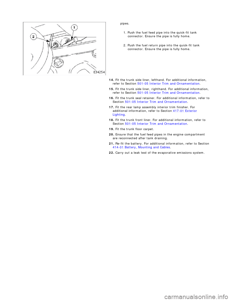
pipes.
1.
Push the fuel feed pipe into the quick-fit tank
connector. Ensu re the pipe is fully home.
2. Push the fuel return pi pe into the quick-fit tank
connector. Ensu re the pipe is fully home.
14. Fit the trunk side liner, lefthand. For additional information,
refer to Section 501
-0 5
Interior Trim and Ornamentation
.
15 . F
it the trunk side liner, righthan
d. For additional information,
refer to Section 501
-0 5
Interior Trim and Ornamentation
.
16 . F
it the trunk seal retainer. For a
dditional information, refer to
Section 501
-05
Interior Trim and Ornamentation
.
17 . F
it the rear lamp assembly
interior trim finisher. For
additional information, refer to Section 417
-01
Exterior
Ligh
ting.
18 . F
it the trunk front liner. For a
dditional information, refer to
Section 501
-05
Interior Trim and Ornamentation
.
19 . F
it the trunk floor carpet.
20. Ensure that the fuel feed pi pes in the engine compartment
are reconnected after tank draining.
21. Re-fit the battery. For additional information, refer to Section
414
-0 1
Battery, Mounting and Cables
.
22 . Carry ou
t a leak test of the evaporative emissions system.
Page 1769 of 2490
Air Distribution and Filtering - Air Distri
bution and Filtering
Description an
d Operation
Air Distribution
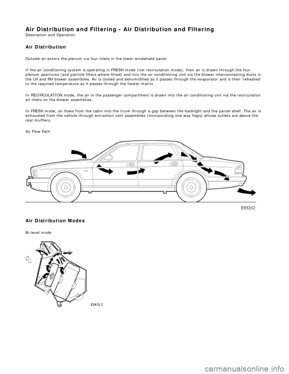
Ou
tside air enters the plen
um via four inlets in the lower windshield panel.
If the air conditioning system is operating in FRESH mode (not recirculation mode), then air is drawn through the four
plenum apertures (and particle filters where fitted) and into the air conditioni ng unit via the blower interconnecting ducts in
the LH and RH blower assemblies. Air is c ooled and dehumidified as it passes through the evaporator and is then 'reheated'
to the required temperature as it passes through the heater matrix.
In RECIRCULATION mode, the air in the pass enger compartment is drawn into the air conditioning unit via the recirculation
air inlets on the blower assemblies.
In FRESH mode, air flows from the cabin into the trunk through a gap between the backlight and the parcel shelf. The air is
exhausted from the vehicle through extraction vent assemblies (incorporating one way flaps) whose outlets are above the
rear mufflers.
Air Flow Path
Air Distribution Modes
Bi
-level mode
Page 1905 of 2490
The CD Autochanger and amplifier are mounte d on a bracket as a single assembly located at the left hand side of the trunk.
The complete assembly must be removed before the CD Autochanger and amplifier can be separated.
When the CD option is selected, the CD unit cycles through a self-check sequence and indicates the current status on the
message display. Refer to the Sound System Ha ndbook for complete operating instructions.
Page 1908 of 2490
Antenna - Antenna
Description and Operation
The electrically operated antenna operates automatically when the Ignition switch is set to position 1 or 2, and the radio
cassette player is switched on , regardless of the status of the tape or CD mode switch.
The antenna motor is protected by a 10A fuse, F9, located in the trunk fuse-box.
Page 1921 of 2490
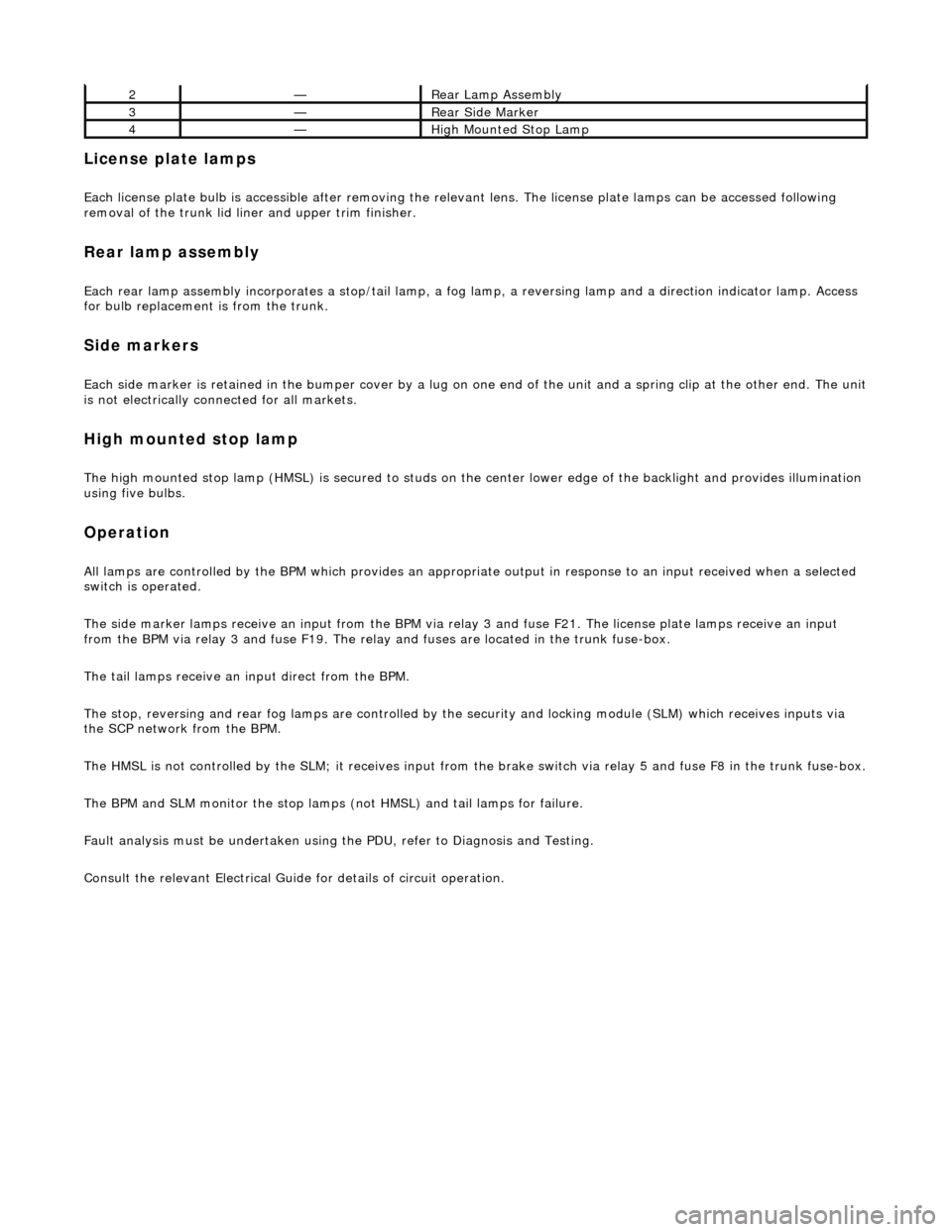
License plate lamps
Each license plate bulb is accessible after removing the relevant lens. The license plate lamps can be accessed following
removal of the trunk lid liner and upper trim finisher.
Rear lamp assembly
Each rear lamp assembly incorporates a stop/tail lamp, a fog lamp, a reversing lamp and a direction indicator lamp. Access
for bulb replacement is from the trunk.
Side markers
Each side marker is retained in the bumper cover by a lug on one end of the unit and a spring clip at the other end. The unit is not electrically connected for all markets.
High mounted stop lamp
The high mounted stop lamp (HMSL) is secu red to studs on the center lower edge of the backlight and provides illumination
using five bulbs.
Operation
All lamps are controlled by the BPM which pr ovides an appropriate output in response to an input received when a selected
switch is operated.
The side marker lamps receive an input from the BPM via relay 3 and fuse F21. The license plate lamps receive an input
from the BPM via relay 3 and fuse F19. The rela y and fuses are located in the trunk fuse-box.
The tail lamps receive an input direct from the BPM.
The stop, reversing and rear fog lamps are controlled by the security and locking module (SLM) which receives inputs via
the SCP network from the BPM.
The HMSL is not controlled by the SLM; it receives input from the brake switch via relay 5 and fuse F8 in the trunk fuse-box.
The BPM and SLM monitor the stop lamps (n ot HMSL) and tail lamps for failure.
Fault analysis must be undertaken using the PDU, refer to Diagnosis and Testing.
Consult the relevant Electrical Guid e for details of circuit operation.
2—Rear Lamp Assembly
3—Rear Side Marker
4—High Mounted Stop Lamp