1998 JAGUAR X308 fuel tank removal
[x] Cancel search: fuel tank removalPage 12 of 2490

Coolant E x
pansion
Tank (26.15.01)
Coolant Outlet Pipe (26.31.08)
Cooling Fan Motor (26.25.24)
Cooling Fan Motor and Shroud (26.25.25)
Cooling Fan Motors (26.25.25)
Cooling Fan Shroud (26.25.30)
Engine Coolant Level Switch (26.40.11)
Radiator (26.40.01) ‐ 3.2L NA V8 ‐ AJ26/4.0L NA V8 ‐ AJ27
Radiator (26.40.01) ‐ 4.0L SC V8 ‐ AJ26
Radiator Lower Hose (26.30.07) ‐ 3.2L NA V8 ‐ AJ26/4.0L NA V8 ‐ AJ27
Radiator Lower Hose (26.30.07) ‐ 4.0L SC V8 ‐ AJ26
Radiator Upper Ho
se (26.30.01) ‐ 3.2L NA V8 ‐ AJ26/4.0L NA V8 ‐ AJ27
Radiator Upper Hose (26.30.01) ‐ 4.0L SC V8 ‐ AJ26
Thermostat (26.45.07) ‐ 3.2L NA V8 ‐ AJ26/4.0L NA V8 ‐ AJ27
Thermostat (26.45.07) ‐ 4.0L SC V8 ‐ AJ26
Thermostat Housing Cover (26.
45.22) ‐ 3.2L NA V8 ‐ AJ26/4.0L NA V8 ‐ AJ27
Thermostat Housing Cover (26.45.22) ‐ 4.0L SC V8 ‐ AJ26
Thermostat Housing Cover Seal (26.45.20) ‐ 3.2L NA V8 ‐ AJ26/4.0L NA V8 ‐ AJ27
Thermostat Housing Cover Seal (26.45.20) ‐ 4.0L SC V8 ‐ AJ26
Water Pump (26.50.
01) ‐ 3.2L NA V8 ‐ AJ26/4.0L NA V8 ‐ AJ27
Water Pump (26.50.01) ‐ 4.0L SC V8 ‐ AJ26
Water Pump Pulley (26.50.05) ‐ 3.2L NA V8 ‐ AJ26/4.0L NA V8 ‐ AJ27
Water Pump Pulley (26.50.05) ‐ 4.0L SC V8 ‐ AJ26
303‐03B : Supercharger Cooling
Removal and Installation
Water Pump
303‐04: Fu
el Charging and Controls
Diagnosis and Testing
Fuel Charging and Controls
Inspection and Verification
Driver Information Chart
Default mode Definitions
Diagnostic Trouble Code (DTC) index
Pinpoint Tests
Page 15 of 2490

Superchar
ger
Outlet Pipe (18.50.16)
Supercharger Outlet Pipe Gasket (18.50.17)
Throttle Body Elbow (19.70.28)
Throttle Body Elbow Gasket (19.70.29)
303‐13: Evaporative Emissions
Diagnosis and Testing
Evaporative Emissions
Preliminary
Inspection
Diagnostic
Drive Cycles
Diagnostic
Trouble Code (DTC) index/Symptom Chart
Pinpoint
Tests
Removal
and Installation
Evaporative
Emission Canister (17.15.13)
Evaporative
Emission Canister Purge Valve (17.15.30)
Fuel
Tank Press
ure Sensor (19.55.31)
Fuel
Vapor Vent Valve Housing (19.55.24)
Fuel
Vapor Vent Valve Housing Seal (19.55.25)
303
‐14: Electronic Engine Controls
Description
and
Diagnosis
and Testing
Electronic
Engine Con
trols
Inspection
and Verification
Driver
Information Chart
Default
mode Definitions
Diagnostic
Trouble Code (DTC) Index
Pinpoint
Tests
Removal
and Installation
Catalyst
Monitor Sensor LH (18.30.81)
Catalyst
Monitor Sensor RH (18.30.80)
Heated Oxygen Sensor (HO2S) LH (18.30.79)
Heated Oxygen Sensor (HO2S) RH (18.30.78)
Camshaft
Position
Sen s
or
ECM
Position
Sensor
Crankshaft
Removal
Engine
Coolant Temperature
Sensor
Operation
Intake Air Temperature (IAT) Sensor (18.
30.52)
Page 19 of 2490

309: Exhaust Syst
em
309‐00: Exhaust System
Specification
Description and Operation
Exhaust System
Diagnosis and Testing
Exhaust System
Removal and Installation
Catalytic Converter LH (17.50.15) ‐ 3.2L NA V8 ‐ AJ26/4.0L NA V8 ‐ AJ27
Catalytic Converter LH (17.50.15) ‐ 4.0L SC V8 ‐ AJ26, Vehicles With:
Supercharger
Catalytic Converter RH (17.50.16) ‐ 3.2L NA V8 ‐ AJ26/4.0L NA V8 ‐ AJ27
Catalyt
ic Converter RH (17.50.16) ‐ 4.0L SC V8 ‐ AJ26, Vehicles With:
Supercharger
Catalytic Converter Gasket LH (17.50.06) ‐ 3.2L NA V8 ‐ AJ26/4.0L NA V8 ‐ AJ27
Catalytic Converter Gasket LH (17.50.06) ‐ 4.0L SC V8 ‐ AJ26
Catalytic Converter Gasket RH (17.50.07) ‐ 3.2L NA V8 ‐ AJ26/4.0L NA V8 ‐ AJ27
Catalyt
ic Converter Gasket RH (17.50.07) ‐ 4.0L SC V8 ‐ AJ26
Front Muffler (30.10.18) ‐ 3.2L NA V8 ‐ AJ26/4.0L NA V8 ‐ AJ27
Front Muffler (30.10.18) ‐ 4.0L SC V8 ‐ AJ26
Intermediate Muffler LH (30.10.15) ‐ 3.2L NA V8 ‐ AJ26/4.0L NA V8 ‐ AJ27
Intermediate Muffler LH (30.10.15) ‐ 4.0L SC V8 ‐ AJ
26
Intermediate Muffler RH (30.10.16) ‐ 3.2L NA V8 ‐ AJ26/4.0L NA V8 ‐ AJ27
Intermediate Muffler RH (30.10.16) ‐ 4.0L SC V8 ‐ AJ26
Muffler and Tailpipe LH (30.10.22)
Muffler and Tailpipe RH (30.10.52)
310: Fuel System
310‐00: Fuel System ‐ General Information
General Procedures
Fuel System Pressure Check
Fuel Tank Draining
Fuel Sy stem Pres
sure
Release
Page 20 of 2490

310‐01: Fu el Tank and Lines
Removal and Installation
Fuel Level Sensor (88.25.32)
Fuel Pump (19.45.08)
Fuel Tank (19.55.01)
310‐02
:
Acceleration Control
General Procedures
Accelerator Cable Adjustment (12.20.05)
Removal and Installation
Accelerator Cable (19.20.06)
310‐03: Speed Control
Diagnosis and Testing
Speed Con
trol
4: Electrical
412: Climate Control System
412‐00: Climate Control System ‐ General Information
Specification
Description and Operation
Climate Control System
Diagnosis and Testing
Climate Control System
General Procedures
Air Conditioning (A/C) System Check ‐ Retail Procedure
Air Conditioning (A/C) System Recovery, Evacuation and Charging (82.30.30)
Contaminated Refrigerant Ha
ndling
Manifold Gauge Set Connection
Refrigerant Adding (82.30.02)
Refrigerant Oil Adding
Refrigerant System Tests
412‐01: Air Distribution and Filtering
Description and Operation
Page 1158 of 2490

The fuel fil
ler cap is the same as
that used on non-ORVR systems.
The check valve assembly is a push fit into the end of the fuel filler tube and is accessible with the evaporative flange
removed. The valve has a light spring load ing and opens under the inflow of fuel.
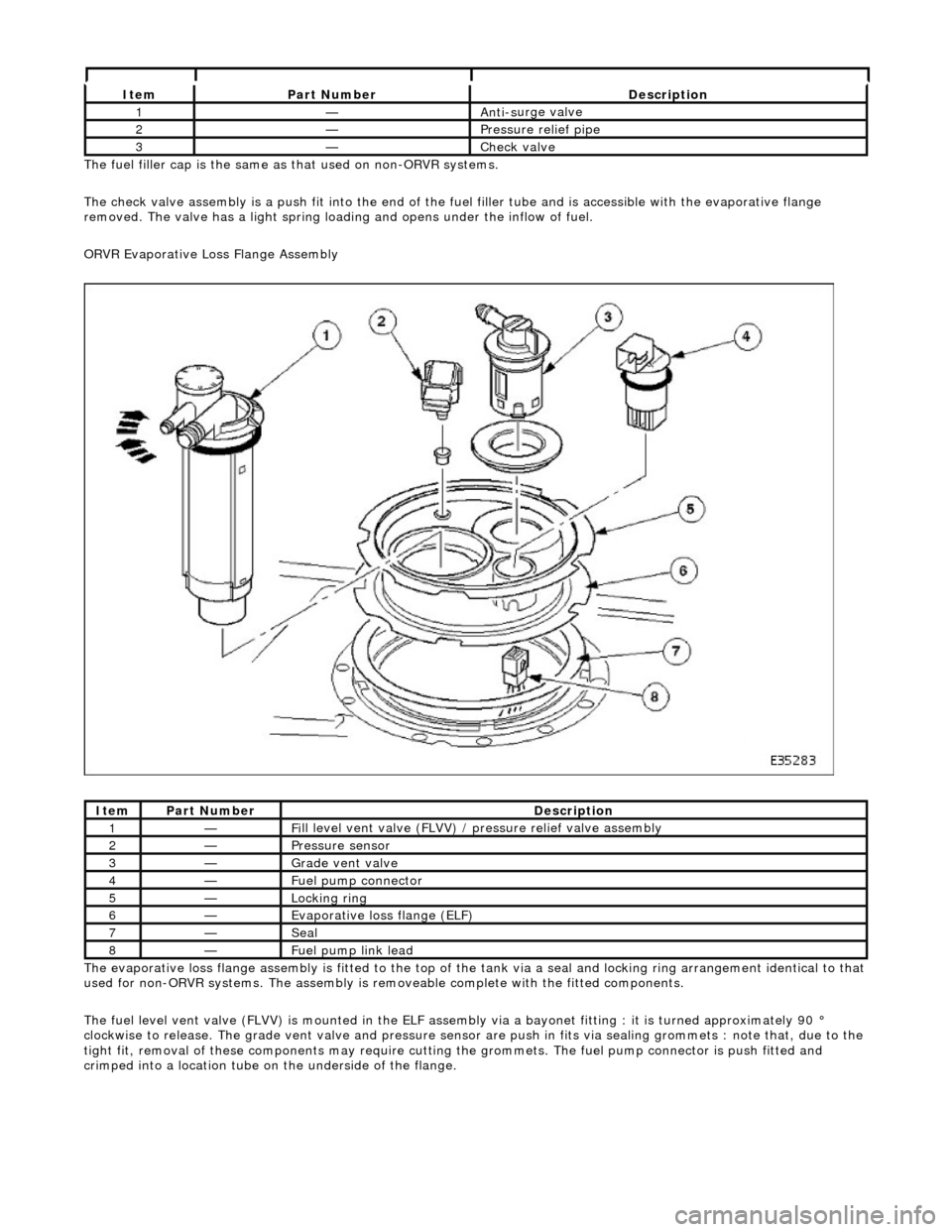
ORVR Evaporative Loss Flange Assembly
The evaporative loss flange assembly is fitted to the top of the tank via a seal and locking ring arrangement identical to that
used for non-ORVR systems. The assembly is re moveable complete with the fitted components.
The fuel level vent valve (FLVV) is mounted in the ELF assembly via a bayonet fitting : it is turned approximately 90 °
clockwise to release. The grade vent valve and pressure sensor are push in fits via sealing gromme ts : note that, due to the
tight fit, removal of these components may require cutting the grommets. The fuel pump connector is push fitted and
crimped into a location tube on the underside of the flange.
It e
m
Par
t
Number
De
scr
iption
1—An
ti-s
urge valve
2—Pressure rel
i
ef pipe
3—Check v
a
lve
It
e
m
Par
t
Number
De
scr
iption
1—Fi
ll
level vent valve (FLVV) /
pressure relief valve assembly
2—Pres
sure
sensor
3—Grade vent
valve
4—Fue
l
pump connector
5—Lockin
g rin
g
6—Evaporative loss flange (ELF)
7—Seal
8—F
u
el pump link lead
Page 1173 of 2490

Evapor
ative Emissions - Fuel Va
por Vent Valve Housing Seal
Remov
al and Installation
Re
moval
• NO
TE: The Removal and Installation procedur
es below show one type of flange but are applicable to the other evaporative loss systems
described.
Special To
ol(s)
Lock
Ring Wrench - Fuel Tank Flange
412-070 (JD 174)
1. Remove battery. Refer to 86.15.01.
2. WARNING: BEFORE PROCEEDING, IT IS ESSENTIAL THAT THE
WARNING NOTES GIVEN IN SECTIO N 100-00 (UNDER THE HEADING
'SAFETY PRECAUTIONS') ARE READ AND UNDERSTOOD.
Remove fuel tank assembly for access. Refer to operation 19.55.01.
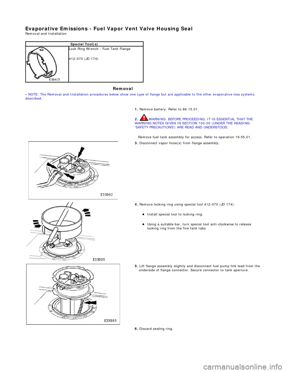
3. Discon
nect vapor hose(s) from flange assembly.
4. Remov
e locking ring using special tool 412-070 (JD 174).
Insta
ll special tool to locking ring.
Usi
ng a suitable bar, turn special tool anti-clockwise to release
locking ring from the five tank tabs.
5. Lift
flange assembly slightly and disconnect fuel pump link lead from the
underside of flange connector. Secure connector to tank aperture.
6. Discard sealing ring.
Page 1693 of 2490

Filler Cap and P
ipe
The fuel
filler cap with bayonet-type fixi
ng is located beneath a remote-release sp ring-latched lid on the rear saddle panel
on the left-hand-side of the vehicle.
Fuel Pum
p
The fu
el pump(s) is energized by an ECM co
ntrolled relay. Fuel is drawn by this pu mp and supplied to the fuel injectors via
the fuel line, filter and fuel rails.
Servicing of the fuel pump re quires fuel tank removal.
Ev
aporative Loss Flange Assembly
The evaporative-loss flan
ge asse
mbly is mounted centrally on top of the tank. The flange assembly consists of a removeable
steel cap which mounts the evaporative emissions system vapor outlet valves and, if applicable, a pressure sensor. The
external electrical supply to th e fuel pump(s) is also made via a connector on the flange.
The flange assembly is fixed to the tank by a locking ring which is turned usin g special tool JD-174. A seal is fitted between
the flange assembly and the tank. Three di fferent flange assemblies are applicable according to the evaporative emission
system fitted to the vehicle. The fl ange size and fixing are identical fo r the three systems, as described.
Removal of the evaporative flange assembly is necessary to gain access to th e fuel pump(s) and other internal components.
To remove the evaporative fl ange assembly the fuel tank must first be removed.
The evaporative flange variant assemblies are described, together with service information, in Section 303-13.
Fuel R
eturn
Excess fuel
is directed back to
the fuel tank via a return line.
Fuel Pum
p Relay
The
fuel pump relay,
under control of the ECM, switches power to the fuel pump motor.
I
nertia Fuel Shutoff (IFS) Switch
The IF
S switch is located in the right-hand
side footwell behind the footboard carpet . When activated the switch isolates the
ignition system and fuel pump, releases any locked doors and disables unnecessary electrical systems. The system can be
reset by pressing down the flexible cover on the top of the switch.
• NOTE: The doors will not unlock if the IFS switch is tripped when the ignition switch is in position '0'.
Page 1732 of 2490

Fu
el Tank and Lines - Fuel Level Sensor
Remov
a
l and Installation
Removal
Ins
tallation
1.
WA
RNING: BEFORE PROCEEDING, IT IS ESSENTIAL THAT THE
WARNING NOTES GIVEN IN SECTIO N 100-00 (UNDER THE HEADING
'SAFETY PRECAUTIONS') ARE READ AND UNDERSTOOD.
Remove the battery. For additional information, refer to Section 414
-01
Battery, Mounting and Cables
.
2.
Drain
the fuel tank using a suitable suction pump/tanker. If the On-
board Refueling Vapour Recovery (ORVR) system is fitted, refer to
Section 310
-00 Fu
el System
- Gen
e
ral Information
.
3. Remov
e the trunk front liner. For additional information, refer to
Section 501
-05 Interior Trim
and Ornamentation
.
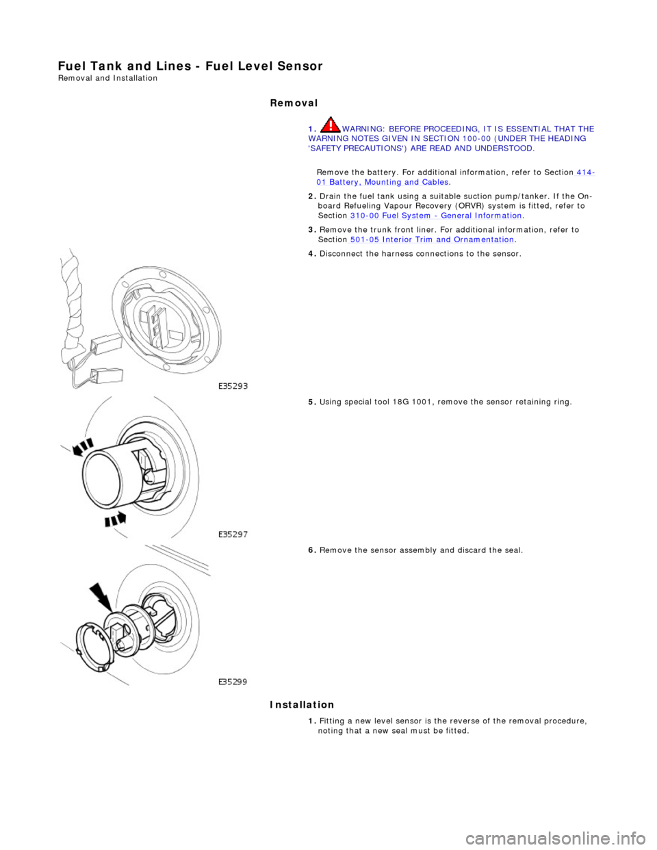
4. D
isconnect the harness co
nnections to the sensor.
5. U
sing special tool 18G 1001, remo
ve the sensor retaining ring.
6.
Remov
e the sensor assembly and discard the seal.
1. Fitting a new level sensor is the reverse of the removal procedure,
noting that a new seal must be fitted.