1998 JAGUAR X308 check engine light
[x] Cancel search: check engine lightPage 315 of 2490

Are th
ere any external brake system leaks?
Yes REPAIR as necessary. ADD fluid and BLEED the brak e system. For additional information, refer to
General Procedures in this section. TEST the system for normal operation.
No GO to F3
.
F
3: CARRY OUT A BRAKE MASTER CYLINDER BYPASS TEST
Te
st for brake master cylinder bypass condition. Re
fer to Brake Master Cylinder Component Test in
this section.
1
A
re any concerns found?
Yes INSTALL a new brake master cylinder, ADD flui d and BLEED the brake system. For additional
information, refer to General Proc edures in this section. TEST the system for normal operation.
No System is OK.
PINPO
INT TEST G : EXCESSIVE BRAKE PEDAL EFFORT
TE
ST
CONDITIONS
D
ETAILS/RESULTS/ACTIONS
G1
: CHECK BRAKE PADS
Check the brake pads for wear, contamin
atio
n, correct installation, damage and type.
1
A
re any concerns found?
Yes INSTALL the front brake pads correctly or INSTALL ne w front brake pads if necessary. For additional
information, refer toSection 206
-03
Front Disc Brake
. INSTALL the
rear brake pads correctly or
INSTALL new rear brake pads if necessary. For additional information, refer toSection 206
-04
Rear
Di
sc Brake
. REPEAT road test.
No
GO to G2
.
G2:
CHECK VACUUM
Di
sconnect the vacuum booster hose from the booster.
1
Conne
ct a vacuum/pressure tester to the vacuum hose.
2
Ru
n the engine at normal operating temperature.
3
Re
cord the vacuum reading.
4
Is
the reading 40.5kPa (1
2 in-Hg) or greater?
Yes GO to G3
.
No
LOCATE and REPAIR the source of low vacuum . TEST the system for normal operation.
G3
: INSPECT SYSTEM
Swi
tch the engine off.
1
Re
connect the vacuum hose.
2
Inspect th
e brake booster, rubber grommet, and al
l vacuum plumbing for cracks, holes, damaged
connections, or missing clamps.
3
Pump th
e brake pedal several time
s to exhaust the vacuum. Push down on the brake pedal and hold.
4
Does th
e brake pedal move down
when the engine is started?
Yes Vacuum system is OK.
No GO to G4
.
G4
: CHECK POWER BRAKE BOOSTER VALVE
Check the brake booster valve. For
add
itional information, refer to
Brake Booster in this section.
1
Is th
e power brake booster valve OK?
Yes CHECK the brake booster. Fo r additional information, refer to Brak e Booster in this section. INSTALL a
new brake booster if necessary. TEST the system for normal operation.
No INSTALL a new brake booster valve. TEST the system for normal operation.
P
INPOINT TEST H : BRAKE LOCKUP
DURING LIGHT BRAKE PEDAL FORCE
TE
ST
CONDITIONS
D
ETAILS/RESULTS/ACTIONS
H1
: TEST BRAKE LOCKUP
Page 318 of 2490

Comp
onent Tests
Bra
k
e Booster
1.
1. Chec k all
hoses and connections. All unused vacuum connectors should be capped. Hoses and their connections
should be correctly secured and in good condition with no holes and no collapsed areas. Inspect the valve on the
brake booster for damage.
2. 2. Check the hydraulic brake system for leaks or low fluid.
3. 3. With the transmission in PARK, stop the engine and apply the parking brake. Pump the brake pedal several times
to exhaust all vacuum in the system.
4. 4. With the engine switched off and all vacuum in the system exhausted, appl y the brake pedal and hold it down.
Start the engine. If the vacuum system is operating, the brake pedal will tend to move downward under constant
foot pressure. If no motion is felt, the vacuum booster system is not functioning.
5. 5. Remove the vacuum hose from the brake booster. Manifold vacuum should be available at the brake booster end
of the hose with the engine at idle speed and the transm ission in PARK or NEUTRAL. Make sure that all unused
vacuum outlets are correctly capped, hose connectors are correctly secured and vacuum hoses are in good
condition. When it is established that manifold vacuum is available to the brake booster, connect the vacuum hose
to the brake booster and repeat Step 3. If no downward movement of the brake pedal is felt, install a new brake
booster.
6. 6. Operate the engine for a minimum of 10 seconds at a fast idle. Stop the engine and allow the vehicle to stand for
10 minutes. Then, apply th e brake pedal with approximately 89 N ( 20lb) of force. The pedal feel (brake
application) should be the same as that noted with the engine running. If the brake pedal feels hard (no power
assist), install a new valve and then re peat the test. If the brake pedal still feels hard, in stall a new brake booster.
If the brake pedal movement feels spongy, bleed the brak e system. For additional information, refer to General
Procedures in this section.
Bra k
e Master Cylinder
Usual
l
y, the first and strongest
indicator of anything wrong in the brake syst em is a feeling through the brake pedal. In
diagnosing the condition of the brake master cylinder, check pedal feel as evidence of a brake concern. Check for brake
warning lamp illumination and the brake fluid le vel in the brake master cylinder reservoir.
Normal Conditio
ns
The fo
llowing conditions are considered norm
al and are not indications that the brake master cylinder is in need of repair.
New bra
ke systems are designed to produc
e a pedal effort that is not as hard as in the past. Complaints of light
pedal efforts should be compared to the pedal effort s of another vehicle of the same model and year.
The fl
uid level will fall with brake pad wear.
Abnormal Conditions
•
NOTE: Prior to carrying out any diag
nosis, make sure the brake system warning indicator is functional.
Changes in the brake pedal feel or brake pedal travel are in dicators that something could be wrong in the brake system. The
diagnostic procedure and techniques use brake pedal feel, warning indicator illu mination and low brake fluid level as
indicators to diagnosing brake system co ncerns. The following conditions are cons idered abnormal and indicate that the
brake master cylinder is in need of repair:
Brake ped a
l goes down fast. Th
is could be caused by an ex ternal or internal leak.
Brake pedal goes down slowly
. This could be
caused by an internal or external leak.
Brak
e pedal is low or feels spongy. This condition may be ca
used by no fluid in the brake master cylinder, reservoir
Page 607 of 2490

3.
F
it the tool to the crankshaft.
E
nsure that the cent
re bolt is unscrewed to below the face
which is to fit to the crankshaft and position the tool to the
crankshaft.
Chec
k that the nuts are fully unscrewed and enter the two
bolts to the crankshaft thre ads and lightly tighten.
4. Tigh
ten the nuts, finger tight, to hold the tool assembly against
the seal. Check that the seal and the tool are approximately
parallel to the rear of the engine.
5. Pres
s the seal into the housing.
Ho
ld each bolt stationary, in
turn, and tighten its nut a
small amount (approximately two to three flats) in turn, to
press the seal fully into the housing. until the tool is in
contact with the cylinder block.
6. Remove the tool from the crankshaft.
Chec
k that the seal is located correctly.
7. Fit the drive plate. Refer to Operation 12.53.13.
8. Install the transmission. Refer to Operation 44.20. 01 in
Section 307-01A.
9. Remove the paint protection sheets and close the engine
compartment cover.
10. Connect the battery and fit the battery cover.
Re
fer to the Battery Reconnection Procedure 86.15.15.
Page 610 of 2490

3.
Fit
the tool to the crankshaft.
En
sure that the cent
re bolt is unscrewe d to below the face
which is to fit to the crankshaft and position the tool to the
crankshaft.
Chec k that
the nuts are fully unscrewed and enter the two
bolts to the crankshaft thre ads and lightly tighten.
4. Tight
en the nuts, finger tight, to hold the tool assembly against
the seal. Check that the seal and the tool are approximately
parallel to the rear of the engine.
5. Pres s th
e seal into the housing.
Ho
ld e
ach bolt stationary, in
turn, and tighten its nut a
small amount (approximately two to three flats) in turn, to
press the seal fully into the housing. until the tool is in
contact with the cylinder block.
6. Remove the tool from the crankshaft.
Chec k that
the seal is located correctly.
7. Fit the drive plate. Refer to Operation (SC) 12.53.13.
8. Install the transmission. Refer to Operation 44.20. 01 in
Section 307-01B.
9. Remove the paint protection sheets and close the engine
compartment cover.
10. Connect the battery and fit the battery cover.
Re
fe
r to the Battery Reconnection Procedure 86.15.15.
Page 1020 of 2490

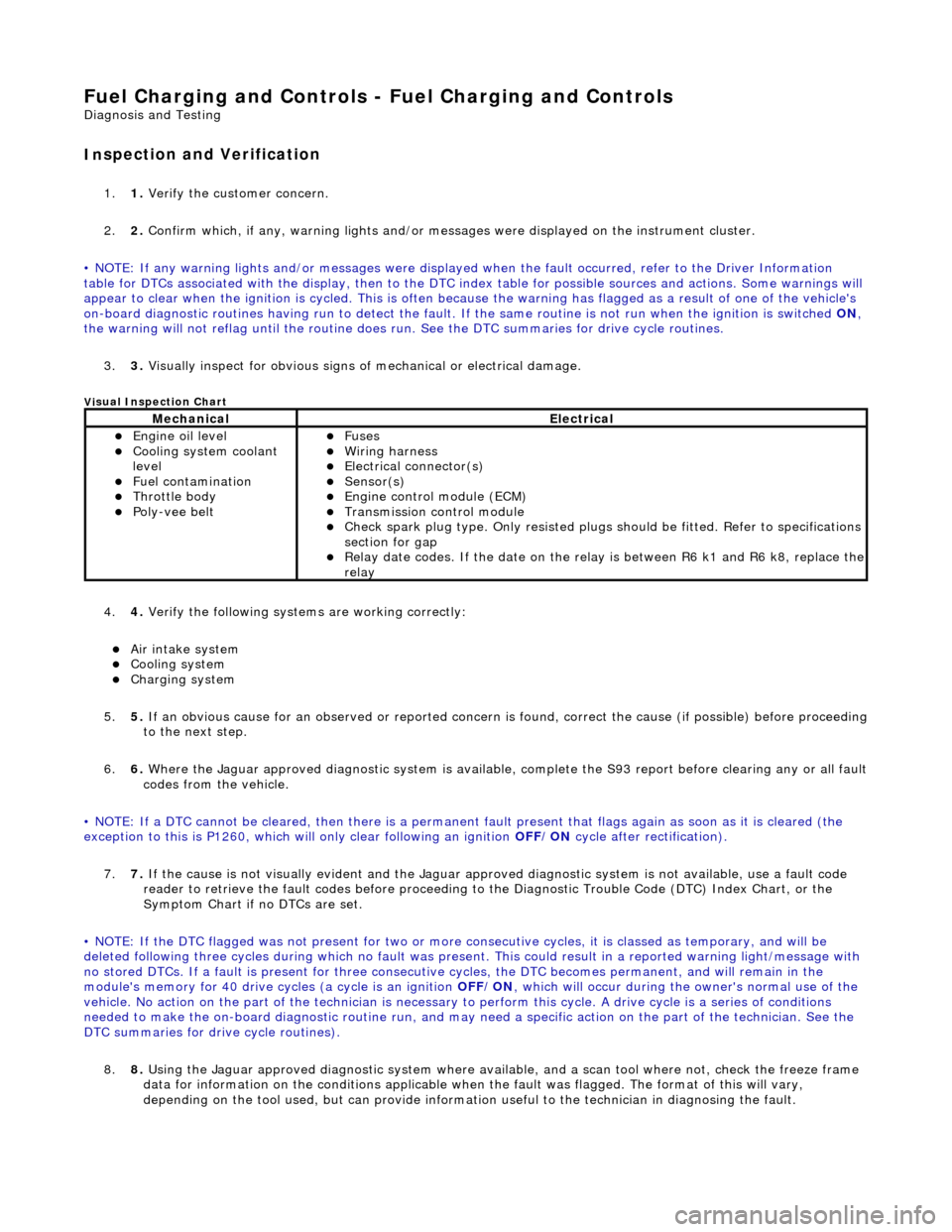
Fuel Char
ging and Controls - Fuel Charging and Controls
D
iagn
osis and Testing
I
n
spection and Verification
1.
1. Veri fy the customer concern.
2. 2. Confi
rm which, if any, warning li
ghts and/or messages were displayed on the instrument cluster.
• NOTE: If any warning lights and/or me ssages were displayed when the fault occurred, refer to the Driver Information
table for DTCs associated with the display, then to the DTC index table for possible sources and actions. Some warnings will
appear to clear when the ignition is cycl ed. This is often because the warning has flagged as a resu lt of one of the vehicle's
on-board diagnostic routines having run to detect the fault. If the same routine is not run when the ignition is switched ON,
the warning will not reflag until the routine does run. See the DTC summaries for drive cycle routines.
3. 3. Visually inspect for obvious signs of mechanical or electrical damage.
Vi
sual Inspection Chart
4.
4. Veri fy the foll
owing syst
ems are working correctly:
Air intake
system
Cooling system
Charging system
5. 5. If
an obvious cause for an observed or
reported concern is found, correct th e cause (if possible) before proceeding
to the next step.
6. 6. Where the Jaguar approved diagnostic sy stem is available, complete the S93 report before clearing any or all fault
codes from the vehicle.
• NOTE: If a DTC cannot be cleared, then there is a permanent fault present that flag s again as soon as it is cleared (the
exception to this is P1260, which will only clear following an ignition OFF/ON cycle after rectification).
7. 7. If the cause is not visually evident and the Jaguar approv ed diagnostic system is not available, use a fault code
reader to retrieve the fault codes be fore proceeding to the Diagnostic Trou ble Code (DTC) Index Chart, or the
Symptom Chart if no DTCs are set.
• NOTE: If the DTC flagged was not present for two or more co nsecutive cycles, it is classed as temporary, and will be
deleted following three cycl es during which no fault was present. This could result in a reported wa rning light/message with
no stored DTCs. If a fault is present for three consecutive cycles, the DTC becomes permanent, and will remain in the
module's memory for 40 drive cycl es (a cycle is an ignition OFF/ON, which will occur during the owner's normal use of the
vehicle. No action on the part of the technician is necessary to perform this cycle. A drive cycle is a series of conditions
needed to make the on-board diagnostic ro utine run, and may need a specific action on the part of the technician. See the
DTC summaries for drive cycle routines).
8. 8. Using the Jaguar approved diagnostic system where available, and a scan tool where not, check the freeze frame
data for information on the conditions applicable when the fault was flagged. The format of this will vary,
depending on the tool used, but can pr ovide information useful to the technician in diagnosing the fault.
MechanicalElectrical
Engine
oil level
Coo
ling system coolant
lev
el
Fuel contamination
Throttle body Poly-ve
e belt
Fu
ses
W
i
ring harness
E
l
ectrical connector(s)
Sens
o
r(s)
Engine
control module (E
CM)
Tran
s
mission control module
Check spark plu
g type. Only r
e
sisted plugs should be fitted. Refer to specifications
section for gap
Relay date codes. I
f the date on the rela
y is between R6 k1 and R6 k8, replace the
relay
Page 1023 of 2490

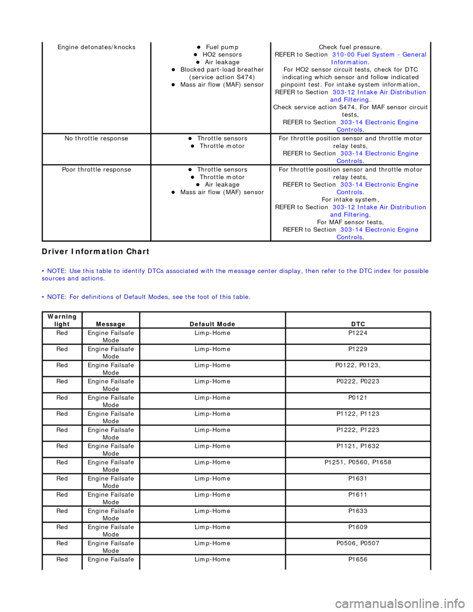
Driver Informa
tion Chart
•
NOTE: Use this table to identify DTCs associated with the me
ssage center display, then refer to the DTC index for possible
sources and actions.
• NOTE: For definitions of Default Modes, see the foot of this table.
Engine deton
ates/knocks
Fue
l pump
HO2 sensors Air leakage Blocked part-load breather
(
service action S474)
Mass ai
r flow (MAF) sensor
Chec
k fuel pressure.
REFER to Section 310
-00
Fuel System
- Gen
eral
Informati
on
.
F
or HO2 sensor circuit
tests, check for DTC
indicating which sensor and follow indicated
pinpoint test. For intake system information,
REFER to Section 303
-1
2 Intake Air Distribution
and F
iltering
.
Check service
action S474. For MAF sensor circuit
tests,
REFER to Section 303
-14 Elec
tronic Engine
Controls.
No
throttle response
Throttl
e sensors
Throttl
e motor
F
or throttle position se
nsor and throttle motor
relay tests,
REFER to Section 303
-14 Elec
tronic Engine
Controls.
Poor throttle responseThrottl
e sensors
Throttl
e motor
Air leakage Mass ai
r flow (MAF) sensor
F
or throttle position se
nsor and throttle motor
relay tests,
REFER to Section 303
-14 Elec
tronic Engine
Controls.
Fo
r intake system,
REFER to Section 303
-1
2 Intake Air Distribution
and F
iltering
.
For MAF
sensor tests,
REFER to Section 303
-14 Elec
tronic Engine
Controls.
Warning
lightMess
age
De
fault Mode
DT
C
Re
d
Engine
Failsafe
Mode
Lim
p-Home
P1224
Re
d
Engine
Failsafe
Mode
Lim
p-Home
P1229
Re
d
Engine
Failsafe
Mode
Lim
p-Home
P01
22, P0123,
Re
d
Engine
Failsafe
Mode
Lim
p-Home
P02
22, P0223
Re
d
Engine
Failsafe
Mode
Lim
p-Home
P0121
Re
d
Engine
Failsafe
Mode
Lim
p-Home
P11
22, P1123
Re
d
Engine
Failsafe
Mode
Lim
p-Home
P12
22, P1223
Re
d
Engine
Failsafe
Mode
Lim
p-Home
P11
21, P1632
Re
d
Engine
Failsafe
Mode
Lim
p-Home
P12
51, P0560, P1658
Re
d
Engine
Failsafe
Mode
Lim
p-Home
P1631
Re
d
Engine
Failsafe
Mode
Lim
p-Home
P1611
Re
d
Engine
Failsafe
Mode
Lim
p-Home
P1633
Re
d
Engine
Failsafe
Mode
Lim
p-Home
P1609
Re
d
Engine
Failsafe
Mode
Lim
p-Home
P05
06, P0507
Re
d
Engine
Failsafe
Lim
p-Home
P1656
Page 1077 of 2490

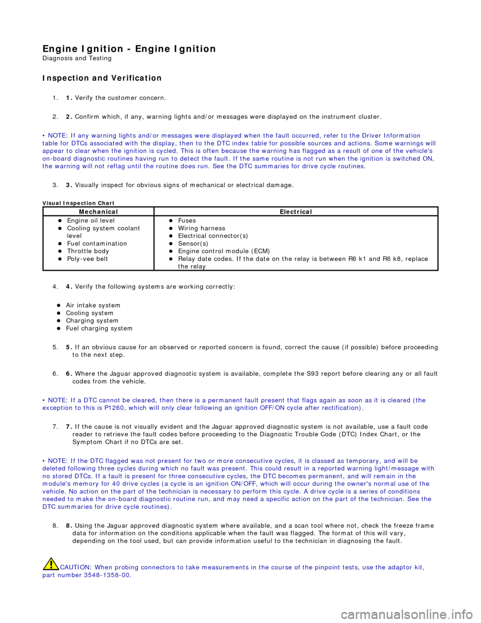
Engine Igni
tion -
Engine Ignition
D
iagnosis and Testing
I
nspection and Verification
1.
1. Veri
fy the customer concern.
2. 2. Confirm which, if any, warning li ghts and/or messages were displayed on the instrument cluster.
• NOTE: If any warning lights and/or me ssages were displayed when the fault occurred, refer to the Driver Information
table for DTCs associated with the display, then to the DTC index table for possible sources and actions. Some warnings will
appear to clear when the ignition is cycl ed. This is often because the warning has flagged as a resu lt of one of the vehicle's
on-board diagnostic routines having run to detect the fault. If the same routine is not run when the ignition is switched ON,
the warning will not reflag until the routine does run. See the DTC summaries for drive cycle routines.
3. 3. Visually inspect for obvious signs of mechanical or electrical damage.
V
isual Inspection Chart
4.
4. Veri
fy the following syst
ems are working correctly:
Air in
take system
Coo
ling system
Charging system
F
uel charging system
5. 5. If an obvious cause for an observed or reported concern is found, correct the cause (if possible) before proceeding
to the next step.
6. 6. Where the Jaguar approved diagnostic sy stem is available, complete the S93 report before clearing any or all fault
codes from the vehicle.
• NOTE: If a DTC cannot be cleared, then there is a permanent fault present that flag s again as soon as it is cleared (the
exception to this is P1260, which will only clear following an ignition OFF/ON cycle after rectification).
7. 7. If the cause is not visually evident and the Jaguar approv ed diagnostic system is not available, use a fault code
reader to retrieve the fault codes be fore proceeding to the Diagnostic Trou ble Code (DTC) Index Chart, or the
Symptom Chart if no DTCs are set.
• NOTE: If the DTC flagged was not present for two or more co nsecutive cycles, it is classed as temporary, and will be
deleted following three cycl es during which no fault was present. This could result in a reported wa rning light/message with
no stored DTCs. If a fault is present for three consecutive cycles, the DTC becomes permanent, and will remain in the
module's memory for 40 drive cycles (a cy cle is an ignition ON/OFF, which will occur during the owner's normal use of the
vehicle. No action on the part of the technician is necessary to perform this cycle. A drive cycle is a series of conditions
needed to make the on-board diagnostic ro utine run, and may need a specific action on the part of the technician. See the
DTC summaries for driv e cycle routines).
8. 8. Using the Jaguar approved diagnostic system where available, and a scan tool where not, check the freeze frame
data for information on the conditions applicable when the fault was flagged. The format of this will vary,
depending on the tool used, but can pr ovide information useful to the technician in diagnosing the fault.
CAUTION: When probing connectors to take measurements in the course of the pinpoint tests, use the adaptor kit,
part number 3548-1358-00.
MechanicalElectrical
Engi
ne oil level
Coo
ling system coolant
level
Fuel contamination
Throttle body Poly
-vee belt
F
uses
W
iring harness
E
lectrical connector(s)
Sens
or(s)
Engine
control module (ECM)
Relay date codes.
If the date on the relay is between R6 k1 and R6 k8, replace
the relay
Page 1189 of 2490

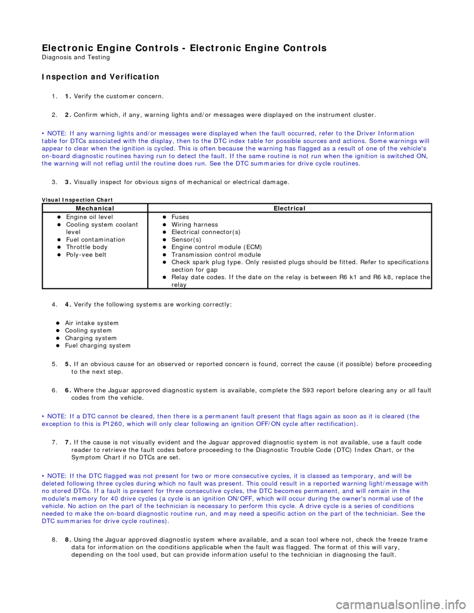
E
lectronic Engine Controls -
Electronic Engine Controls
D
iagnosis and Testing
I
nspection and Verification
1.
1. Veri
fy the customer concern.
2. 2. Confirm which, if any, warning li ghts and/or messages were displayed on the instrument cluster.
• NOTE: If any warning lights and/or me ssages were displayed when the fault occurred, refer to the Driver Information
table for DTCs associated with the display, then to the DTC index table for possible sources and actions. Some warnings will
appear to clear when the ignition is cycl ed. This is often because the warning has flagged as a resu lt of one of the vehicle's
on-board diagnostic routines having run to detect the fault. If the same routine is not run when the ignition is switched ON,
the warning will not reflag until the routine does run. See the DTC summaries for drive cycle routines.
3. 3. Visually inspect for obvious signs of mechanical or electrical damage.
V
isual Inspection Chart
4.
4. Veri
fy the following syst
ems are working correctly:
Air in
take system
Coo
ling system
Charging system
F
uel charging system
5. 5. If an obvious cause for an observed or reported concern is found, correct the cause (if possible) before proceeding
to the next step.
6. 6. Where the Jaguar approved diagnostic sy stem is available, complete the S93 report before clearing any or all fault
codes from the vehicle.
• NOTE: If a DTC cannot be cleared, then there is a permanent fault present that flag s again as soon as it is cleared (the
exception to this is P1260, which will only clear following an ignition OFF/ON cycle after rectification).
7. 7. If the cause is not visually evident and the Jaguar approv ed diagnostic system is not available, use a fault code
reader to retrieve the fault codes be fore proceeding to the Diagnostic Trou ble Code (DTC) Index Chart, or the
Symptom Chart if no DTCs are set.
• NOTE: If the DTC flagged was not present for two or more co nsecutive cycles, it is classed as temporary, and will be
deleted following three cycl es during which no fault was present. This could result in a reported wa rning light/message with
no stored DTCs. If a fault is present for three consecutive cycles, the DTC becomes permanent, and will remain in the
module's memory for 40 drive cycles (a cy cle is an ignition ON/OFF, which will occur during the owner's normal use of the
vehicle. No action on the part of the technician is necessary to perform this cycle. A drive cycle is a series of conditions
needed to make the on-board diagnostic ro utine run, and may need a specific action on the part of the technician. See the
DTC summaries for driv e cycle routines).
8. 8. Using the Jaguar approved diagnostic system where available, and a scan tool where not, check the freeze frame
data for information on the conditions applicable when the fault was flagged. The format of this will vary,
dependin
g o
n the tool used, but can provide information useful to the technician in dia
gnos
in
g th
e fault.
MechanicalElectrical
Engi
ne oil level
Coo
ling system coolant
level
Fuel contamination
Throttle body Poly
-vee belt
F
uses
W
iring harness
E
lectrical connector(s)
Sens
or(s)
Engine
control module (ECM)
Tran
smission control module
Check spark plu
g type. Only re
sisted plugs should be fitted. Refer to specifications
section for gap
Relay date codes.
If the date on the rela
y is between R6 k1 and R6 k8, replace the
relay