Page 550 of 2490

14
. WARNING: TH
E FOLLOWING OPERATIONS REQUIRE
THE USE OF COMPRESSED AIR - ALWAYS WEAR SUITABLE EYE
PROTECTION.
Remove, clean and measure the shims.
1. Surround the immediate wo rking area with clean rag
to contain any loose objects and shims displaced by
the compressed air.
2. Use 303 - 590 Air Gun (with a fan nozzle) aimed at the edge of the shim to lift it from the tappet.
Remove the shim from each tappet, noting the
position of each.
15 . Cl
ean and measure the thickness of each shim.
16. Assess the increase or decrease required in shim thickness to
produce the correct valve clearance.
17. Select two shims of the correct size, lubricate each and fit
each to the respective tappet (as calculated in the previous
step). Shims must be fitted with the size marking facing the
tappet NOT the cam.
18 . Loos
en the knurled screws on 303 - 540 attachment to allow
the valve springs to return to their normal position.
19. Check the valve clearance of the two valves. If the clearance
is correct, remove the attachment from the base plate. transfer
the attachment to the other two valves which are in position to
be adjusted.
20. Repeat the adjustment procedure, as described in the
Summary.
21. Refit the cam covers and associated components. Refer to
Operations 12.29.43 and 12.29.44.
22. Refit the engine covers.
23. Check the engine oil level; rectify as necessary.
24. Move the engine compartment cover from the service position
and connect the gas struts.
25. Remove the paint protection sheets and close the cover.
26. Connect the battery and fit the battery cover.
Refe
r to the Battery Reconnection Procedure 86.15.15.
Page 646 of 2490
In
stallation
27
. Clean all parts and mating faces.
1. Fit ne
w seals to the timing cover.
1. Fit and fully locate, a new seal to the inner groove on the face of the timing cover.
2. Fit and fully locate, a new seal to the outer groove on the face of the timing cover.
Re
move the transit ring and check that the oil seal is not
damaged.
2. Appl y s
ealant to the eight joints on the engine face.
Sealant
beads to be 3mm di ameter an
d 12mm long. Cut
the nozzle of the sealant tube to produce a 3mm bead.
(Fit and tighten the securing bolts within twenty minutes
of sealant application)
3. Re
fit the timing cover, step 1.
Lo
wer th
e cover into the engine compartment, to its
approximate position.
4. Refit the timing cover, step 2.
Stan din
g at the right hand side
of the vehicle, rotate and
manoeuvre the cover downwards to clear the water pump
Page 655 of 2490
I
nstallation
27
.
Remove and discard the inner and outer seals from the timing
cover.
1. Remove the seal from the inner groove on the face of the timing cover.
2. Remove the seal from the outer groove on the face of
the timing cover.
Chec
k the condition of the oil seal and renew as
necessary.
28. Clean all parts and mating faces.
1. Fi
t new seals to the timing cover.
1. Fit and fully locate, a new seal to the inner groove on the face of the timing cover.
2. Fit and fully locate, a new seal to the outer groove on the face of the timing cover.
2. Appl
y sealant to the eight joints on the engine face.
Sealant
beads to be 3mm di
ameter and 12mm long. Cut
the nozzle of the sealant tube to produce a 3mm bead.
(Fit and tighten the securing bolts within twenty minutes
of sealant application)
3. Refit the timing cover, step 1.
Lo
wer the cover into the engine compartment, to its
approximate position.
Page 1156 of 2490

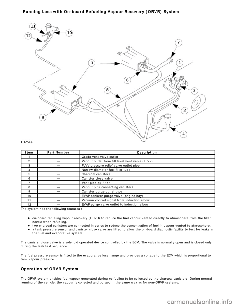
The system has the
following features :
o
n
-board refueling vapour recovery (ORVR) to reduce the fu
el vapour vented directly to atmosphere from the filler
nozzle when refueling.
two ch arcoal
canisters are connected in series to reduce th
e concentration of fuel in vapour vented to atmosphere.
a t
ank pressure sensor and canister close
valve are fitted to allow the on-board di agnostic facility to test for leaks in
the fuel and evaporative system.
The canister close valve is a solenoid operated device controlled by the ECM. The valve is normally open and is closed only
during the leak test sequence.
The fuel pressure sensor is fitted to th e evaporative loss flange and provides a volt age to the ECM which is proportional to
tank vapour pressure.
Op era
tion of ORVR System
The ORVR system enabl
e
s fuel vapour generated during re-fueling to be collected by
the charcoal canisters. During normal
running of the vehicle, the vapour is collected and purged in the same way as for non-ORVR systems.
Ite
m
Par
t
Number
De
scr
iption
1—Grade vent
valve outl
et
2—Vapour outl
et from fil
l level vent valve (FLVV)
3—F
L
VV pressure relief valve outlet pipe
4—N
a
rrow diameter fuel filler tube
5—Charcoal can
i
sters
6—Cani
st
er close valve
7—Vent pi
pe ai
r filter
8—Vapour pipe
conn
ecting canisters
9—Canister purge ou
tlet pipe
10—EVAP canister purge v a
lve (engine bay)
11—Vacuu
m
control signal from induction elbow
12—EVAP pu
rge valve outlet to induction elbow
Running Loss with On-board R
efuelin
g Vapour Recovery (ORVR) System
Page 1157 of 2490

The OR
VR system features are :
N
arrow fuel filler pipe and tank check valve.
Fue
l level vent valve (FLVV) fitted to the evaporative flan
ge and consisting of a two stage shut-off valve with rollover
protection and a pressure relief valve.
Grade ven
t valve with rollover protection, fitted to the ev
aporative flange and with an outlet pipe connected to the
FLVV vapour outlet pipe.
Large bore vapour vent pipes.
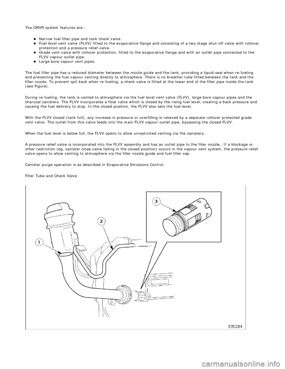
The fuel filler pipe has a reduced diameter between the nozzle guide and the tank, providing a liquid seal when re-fueling
and preventing the fuel vapour venting directly to atmosphere. There is no breather tube fitted between the tank and the
filler nozzle. To prevent spit back when re-fueling, a check valv e is fitted at the lower end of the filler pipe inside the tank
(see Figure).
During re-fueling, the tank is vented to atmosphere via the fuel level vent valv e (FLVV), large bore vapour pipes and the
charcoal canisters. The FLVV incorp orates a float valve which is closed by the rising fuel level, creating a back pressure and
causing the fuel delivery to stop. In the closed position, the FLVV also sets the fuel level.
With the FLVV closed (tank full), any increase in pressure or overfilling is relieved by a separate rollover protected grade
vent valve. The outlet from this valve feeds into the main FLVV vapour outlet pipe, bypassing the closed FLVV.
When the fuel level is below full, the FLVV opens to allow unrestricted venting via the canisters.
A pressure relief valve is incorp orated into the FLVV assembly and has an outlet pipe to the filler nozzle,. If a blockage or
other restriction (eg, canister close valve failing in the closed position) occurs in the vapour vent system, the pressure reli ef
valve opens to allow venting to atmosphere via the filler nozzle guide and fuel filler cap.
Canister purge operation is as described in Evaporative Emissions Control.
Filler Tube and Check Valve
Page 2202 of 2490
spirit.
4. Apply primer to the mating face of the glass.
5. Apply primer to the mating face of the body.
6. Cut the nozzle of the JLM20452 glass bonding adhesive to
achieve a triangular section bead 8 mm (0.32 in) wide by 10
mm (0.4 in) high.
7. Using the special tool, apply a uni form bead of adhesive to the
rear quarter window glass edge commencing at the bottom
center and overlapping the ends approximately 14 mm (0.56
in).
Page 2209 of 2490
3. Thoroughly clean rear window glass surface using Betawipe
spirit.
4. Apply primer to mating face of rear window glass.
5. Apply glass primer to the mating face of the body flange.
6. Cut the nozzle of the JLM20452 glass bonding adhesive to
achieve a triangular section bead 8mm ( 0.32 in) wide by
10mm (0.4 in) high.
7. Using the special tool, apply a uni form bead of adhesive to the
rear window glass edge, commen cing at bottom center and
overlapping the ends approximately 14 mm (0.56 in).
Page 2216 of 2490
4. Thoroughly clean windshield glass surface using Betawipe
spirit.
5. Apply primer to mating fa ce of windshield glass.
6. CAUTION: Make sure the front windshield finisher insert
is not bent on installation. Failure to follow this instruction may
result in damage to the component.
Install the insert to the windshield finisher.
7. CAUTION: Make sure the front windshield finisher insert
is not bent on installation. Failure to follow this instruction may
result in damage to the component.
Install the windshield finisher to the windshield.
8. Cut the nozzle of the JLM20452 glass bonding adhesive to
achieve a triangular section bead 8mm ( 0.32 in) wide by
10mm (0.4 in) high.