Page 928 of 2490
combin
ed with the outlet duct and consequently, there is no separate housin
g assembly fitted above the water pump, as used
on the normally aspirated engine. The illustration shows the outlet duct viewed from the engine.
Thermostat Housing
The plastic housing for the thermostat is fitted between th e two cylinder banks immediately above the coolant pump.
Controlling the coolant flow through the radiator, the thermostat starts to open at 80 ° to 84 °C and is fully open at 96 °C.
A duct in the cylinder block connects the thermostat housing outlet to the coolant pump inlet. The joint between the
thermostat housing and the cylinder block is via an in-groove seal.
An air bleed outlet vents an y air in the system into the expansion reservoir, durin
g normal operation. A removable cap (usin g
a hex key) allows air to vent from the system when filling from empty.
On supercharged engines, the thermostat housin g is combined with the coolant outlet duct.
Radiator
Page 930 of 2490

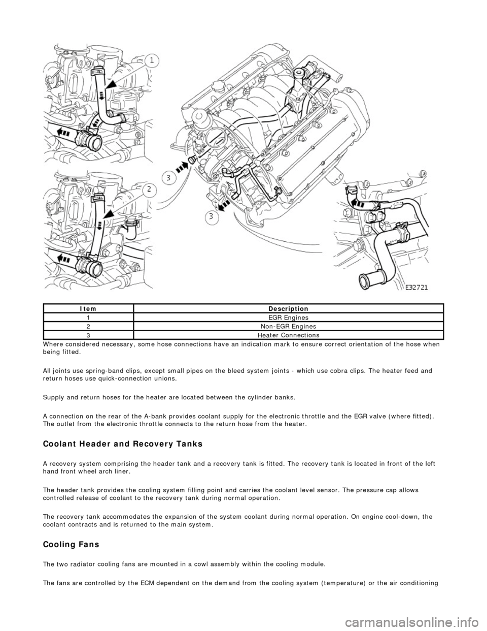
Whe r
e considered necessary, some hose conn
ections have an indication mark to ensure correct orientation of the hose when
being fitted.
All joints use spring-band clips, except small pipes on the bleed system joints - which use cobra clips. The heater feed and
return hoses use quick-connection unions.
Supply and return hoses for the heater are located between the cylinder banks.
A connection on the rear of the A-bank provides coolant supply for the electronic throttle and the EGR valve (where fitted).
The outlet from the electronic throttle connects to the return hose from the heater.
Cool
ant Header and Recovery Tanks
A recovery system comp
rising the header tank
and a recovery tank is fitted. The recove ry tank is located in front of the left
hand front wheel arch liner.
The header tank provides the cooling system filling point and carries the coolant level sensor. The pressure cap allows
controlled release of coolant to the re covery tank during normal operation.
The recovery tank accommodates the expansion of the system coolant during normal operation. On engine cool-down, the
coolant contracts and is returned to the main system.
Coo lin
g Fans
The two
rad
iator cooling fans are mounted in
a cowl assembly within the cooling module.
The fans are controlled by the ECM dependent on the demand fr om the cooling system (temperature) or the air conditioning
ItemDescrip
tion
1EGR
E
ngines
2Non
-
EGR Engines
3Hea
ter Connections
Page 1111 of 2490

the
intake elbow provide connections for vacuum actuators and are also used to redirect emissions into the engine.
On the right-hand side of the elbow a la rge diameter pipe connects to the brake servo. The smaller pipe provides a vacuum
feed to the fuel rail pressure regulator and throttle cruise control system. On the le ft-hand side of the elbow the front pipe
supplies vacuum control for the evaporative emissions system valves.
Emissions from the engine part load breather (bank 2) and pu rged fuel vapor from the EVAP valve are drawn via a common
T piece into the left-hand side of the intake elbow. Re-cir culated exhaust gas enters the intake elbow via the EGR valve
which is mounted directly on the rear of the elbow : where the EGR system is not used, a blanking plate is fitted.
The fuel system, throttle and emission control system s are described more fully in the relevant sections.
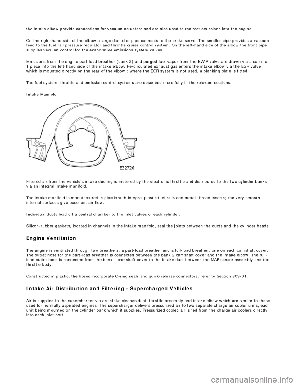
Intake Manifold
Filtered air from the vehicle's intake ducting is metered by th e electronic throttle and distributed to the two cylinder banks
via an integral intake manifold.
The intake manifold is manufactured in plastic with integral plastic fuel rails and metal-thread inserts; the very smooth
internal surfaces give excellent air flow.
Individual ducts lead off a central chamber to the inlet valves of each cylinder.
Silicon-rubber gaskets, loca ted in channels in the intake manifold, seal th e joints between the ducts and the cylinder heads.
Engine Ventilation
The e
ngine is ventilated through two brea
thers; a part-load breather and a full-load breather, one on each camshaft cover.
The outlet hose for the part-load breather is connected between the bank 2 camshaft cover and the intake elbow. The full-
load outlet hose is connected from the bank 1 camshaft cover to the intake duct between the MAF sensor assembly and the
throttle body.
Constructed in plastic, the hoses incorporate O-ring seal s and quick-release connectors; refer to Section 303-01.
I
ntake Air Distribution and Filtering - Supercharged Vehicles
Ai
r is supplied to the supercharger via an
intake cleaner/duct, throttle assembly and intake elbow which are similar to those
used for normally aspirated engines. The su percharger delivers pressurized air to two separate charge air cooler units, each
unit being mounted on the cy linder bank which it supplies. Pr essurized cooled air is fed from the charge air coolers directly
into each inlet port.
Page 1163 of 2490

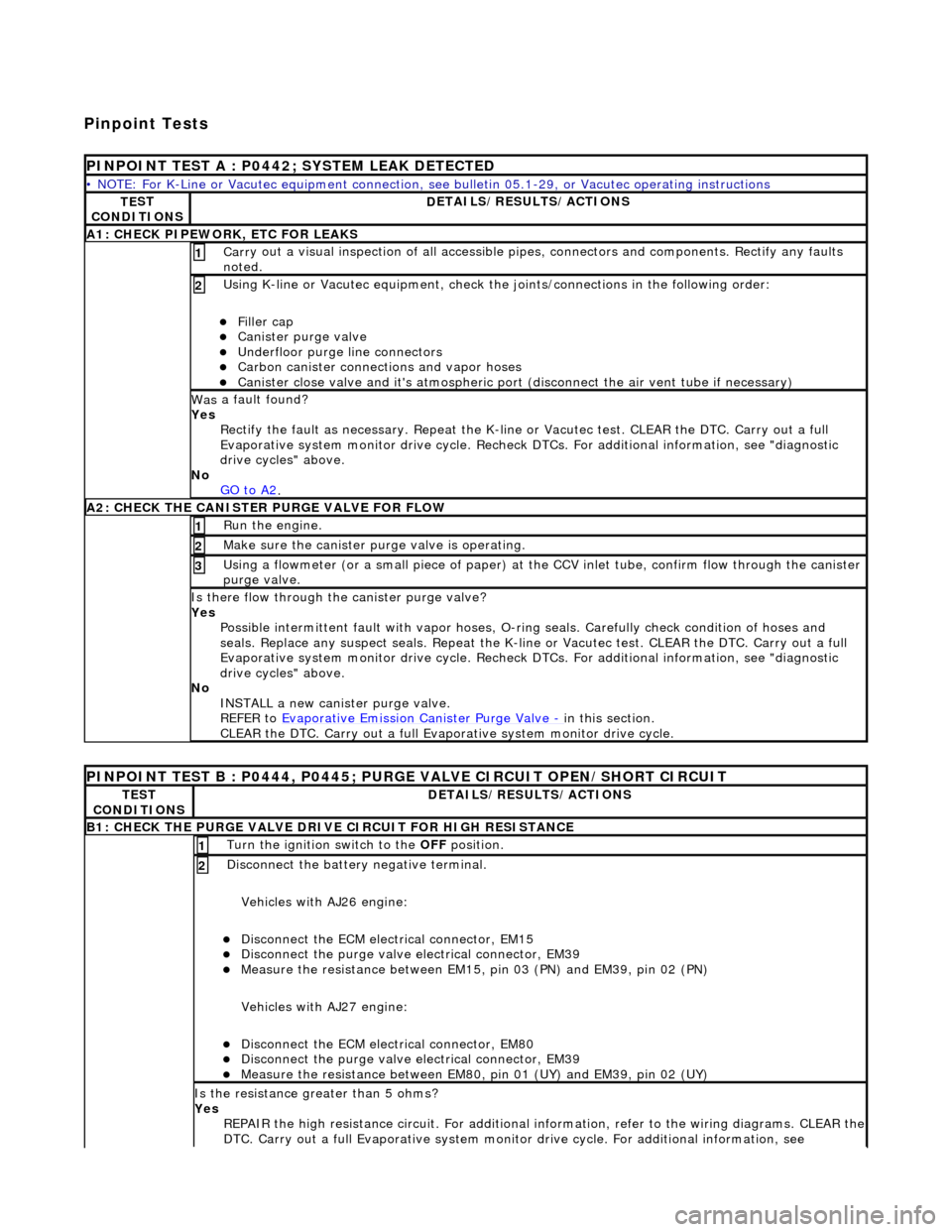
Pinpoint Tests
P
INPOINT TEST A : P0442; SYSTEM LEAK DETECTED
•
NOTE: For K-Line or Vacutec equipment connection, see bulletin 05.1-29, or Vacutec operating instructions
TE
ST
CONDITIONS
D
ETAILS/RESULTS/ACTIONS
A
1: CHECK PIPEWORK, ETC FOR LEAKS
Carr
y out a visual inspection of all accessible pipes, connectors and components. Rectify any faults
noted.
1
U
sing K-line or Vacutec equipment, check the
joints/connections in the following order:
Fi
ller cap
Cani
ster purge valve
Underfl
oor purge line connectors
Carbon
canister connections and vapor hoses
Cani
ster close valve and it's atmospheric port (disconnect the air vent tube if necessary)
2
Was
a fault found?
Yes Rectify the fault as necessary. Re peat the K-line or Vacutec test. CLEAR the DTC. Carry out a full
Evaporative system monitor drive cycle. Recheck DT Cs. For additional information, see "diagnostic
drive cycles" above.
No GO to A2
.
A2: CHECK
THE CA
NISTER PURGE VALVE FOR FLOW
Ru
n the engine.
1
Make sure the canister purge
valve is operating.
2
Using a flowmeter
(or a small piece
of paper) at the CCV inlet tube, confirm flow through the canister
purge valve.
3
Is th
ere flow through the canister purge valve?
Yes Possible intermittent faul t with vapor hoses, O-ring seals. Carefully check condition of hoses and
seals. Replace any suspect seals. Repeat the K-line or Vacutec test. CLEAR the DTC. Carry out a full
Evaporative system monitor drive cycle. Recheck DT Cs. For additional information, see "diagnostic
drive cycles" above.
No INSTALL a new canister purge valve.
REFER to Evaporative Emission Canister Purge Valve
- in t
his section.
CLEAR the DTC. Carry out a full Evap orative system monitor drive cycle.
P
INPOINT TEST B : P0444, P0445; PURGE VALVE CIRCUIT OPEN/SHORT CIRCUIT
TE
ST
CONDITIONS
D
ETAILS/RESULTS/ACTIONS
B1: CHECK
THE PURGE VALVE DRIV
E CIRCUIT FOR HIGH RESISTANCE
Turn the ignition swi
tch to the OFF
position.
1
Di
sconnect the battery negative terminal.
Vehicles with AJ26 engine:
Disc
onnect the ECM electrical connector, EM15
Di
sconnect the purge valve electrical connector, EM39
Meas
ure the resistance between EM15,
pin 03 (PN) and EM39, pin 02 (PN)
Vehicles with AJ27 engine:
Disc
onnect the ECM electrical connector, EM80
Di
sconnect the purge valve electrical connector, EM39
Meas
ure the resistance between EM80, pin 01 (UY) and EM39, pin 02 (UY)
2
Is th
e resistance greater than 5 ohms?
Yes REPAIR the high resistance circuit. For additional information, refer to the wiring diagrams. CLEAR the
DTC. Carry out a full Evaporative system monitor drive cycle. For additional information, see
Page 1525 of 2490
The left-hand and right-hand do wnpipe assemblies feature:
Catalytic converter with palladium / rhodium coated elem ents. The elements are uncoated for markets with only
leaded fuel.
Retained to the exhaust manifold flange by four thread ed studs. Joint-to-joint sealing is with a gasket. Engine-mounted bracket providing downpipe mounting by two nuts to the torque converter housing and two bolts to
the downpipe.
Front Muffler Assembly
ItemPart NumberDescription
1—Downpipe catalytic converter
2—Upstream heated oxygen sensor
3—Downstream oxygen sensor (North American markets only)
4—Engine mounting bracket (LHS and RHS)
Page 1526 of 2490
The front muffler assembly features:
Twin-pipe absorption type muffler. Pipe-to-pipe pres sure damping. Inlet and outlet pipes welded to the muffler. Front joints are flanged on supercharged engines and a flexible pipe (not removable separately ) is fitted behind each
flange - refer to the inset above.
Intermediate Muffler Assembly
The left- and right-hand intermedia te muffler assemblies comprise:
Absorption type muffler. Inlet and outlet pipes welded to the muffler.
Page 1528 of 2490
Joints and Clamps
Pipe-to-pipe joints which are slip joints, feature:
Clamping by Torca strap clamp. Indicator rings providing Maximum, Mini mum and Nominal engagement marks.
Oxygen Sensor (O2)
Location
Page 1639 of 2490
I
nstallation
7.
R
aise the vehicle on a ramp.
8. R
emove the downpipe catalytic converter.
R
emove the bolts which se
cure the downpipe lower
mounting bracket.
Remove the
downpipe assembly.
9. R
emove the oxygen sensor(s).
The downstream sensor i
s fitt
ed only for North American
markets.
10. Remove gasket from the manifold flange.
Clean and inspect th
e manifold joint faces.
Clean and inspect th
e threads
on the downpipe studs.
1. Fit the oxygen sensor(s).
The downstream sensor i
s fitt
ed only for North American
markets.