1998 JAGUAR X308 Joint
[x] Cancel search: JointPage 1682 of 2490
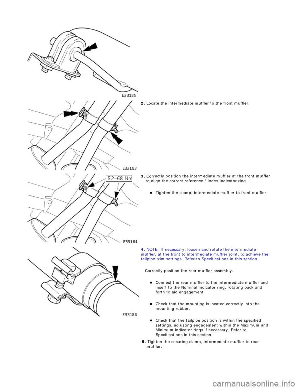
2. Locate the intermediate muffl er to the front muff
ler.
3. Cor r
ectly position the intermedia
te muffler at the front muffler
to align the correct refere nce / index indicator ring.
Tighte
n the clamp, intermediate
muffler to front muffler.
4. NO TE
: If necessary, loosen and rotate the intermediate
muffler, at the front to intermediate muffler joint, to achieve the
tailpipe trim settings. Refer to Specifications in this section.
Correctly position the rear muffler assembly.
Connect the rear muffl
er to the intermediate muffler and
insert to the Nominal indicator ring, rotating back and
forth to aid engagement.
Chec k
that the mounting is located correctly into the
mounting rubber.
Chec k
that the tailpi
pe position is wi thin the specified
settings, adjusting engageme nt within the Maximum and
Minimum indicator rings if necessary. Refer to
Specifications in this section.
5. Tighten the securing clamp, in termediate muffler to rear
muffler.
Page 1684 of 2490
Ex
haust System - Muff
ler and Tailpipe LH
Remo
val and Installation
Remov
a
l
Installation
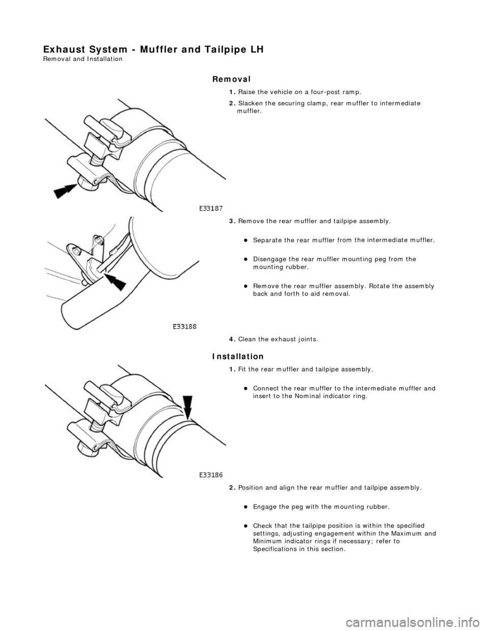
1. Ra
ise the vehicle on a four-post ramp.
2. Slacken the securi
ng clamp, re
ar muffler to intermediate
muffler.
3. Re
move the rear muffler
and tailpipe assembly.
Separate the rear muffl er fr
om
the intermediate muffler.
Di
sengage the rear muffler mounting peg from the
mounting rubber.
R e
move the rear muffler asse
mbly. Rotate the assembly
back and forth to aid removal.
4. Clean the exhaust joints.
1. Fi
t the rear muffler and tailpipe assembly.
Connect
the rear muffl
er to the intermediate muffler and
insert to the Nominal indicator ring.
2. Position and align the rear mu ffler and tailpipe assembly.
Engage the peg with
the mounting rubber.
Chec
k
that the tailpi
pe position is wi thin the specified
settings, adjusting engageme nt within the Maximum and
Minimum indicator rings if necessary; refer to
Specifications in this section.
Page 1686 of 2490
Ex
haust System - Muff
ler and Tailpipe RH
Remo
val and Installation
Remov
a
l
Installation
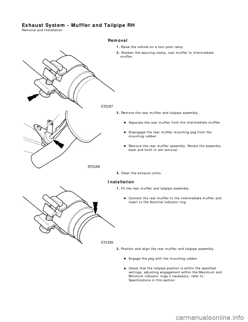
1. Ra
ise the vehicle on a four-post ramp.
2. Slacken the securi
ng clamp, re
ar muffler to intermediate
muffler.
3. Re
move the rear muffler
and tailpipe assembly.
Separate the rear muffl er fr
om
the intermediate muffler.
Di
sengage the rear muffler mounting peg from the
mounting rubber.
R e
move the rear muffler asse
mbly. Rotate the assembly
back and forth to aid removal.
4. Clean the exhaust joints.
1. Fi
t the rear muffler and tailpipe assembly.
Connect
the rear muffl
er to the intermediate muffler and
insert to the Nominal indicator ring.
2. Position and align the rear mu ffler and tailpipe assembly.
Engage the peg with
the mounting rubber.
Chec
k
that the tailpi
pe position is wi thin the specified
settings, adjusting engageme nt within the Maximum and
Minimum indicator rings if necessary; refer to
Specifications in this section.
Page 1756 of 2490
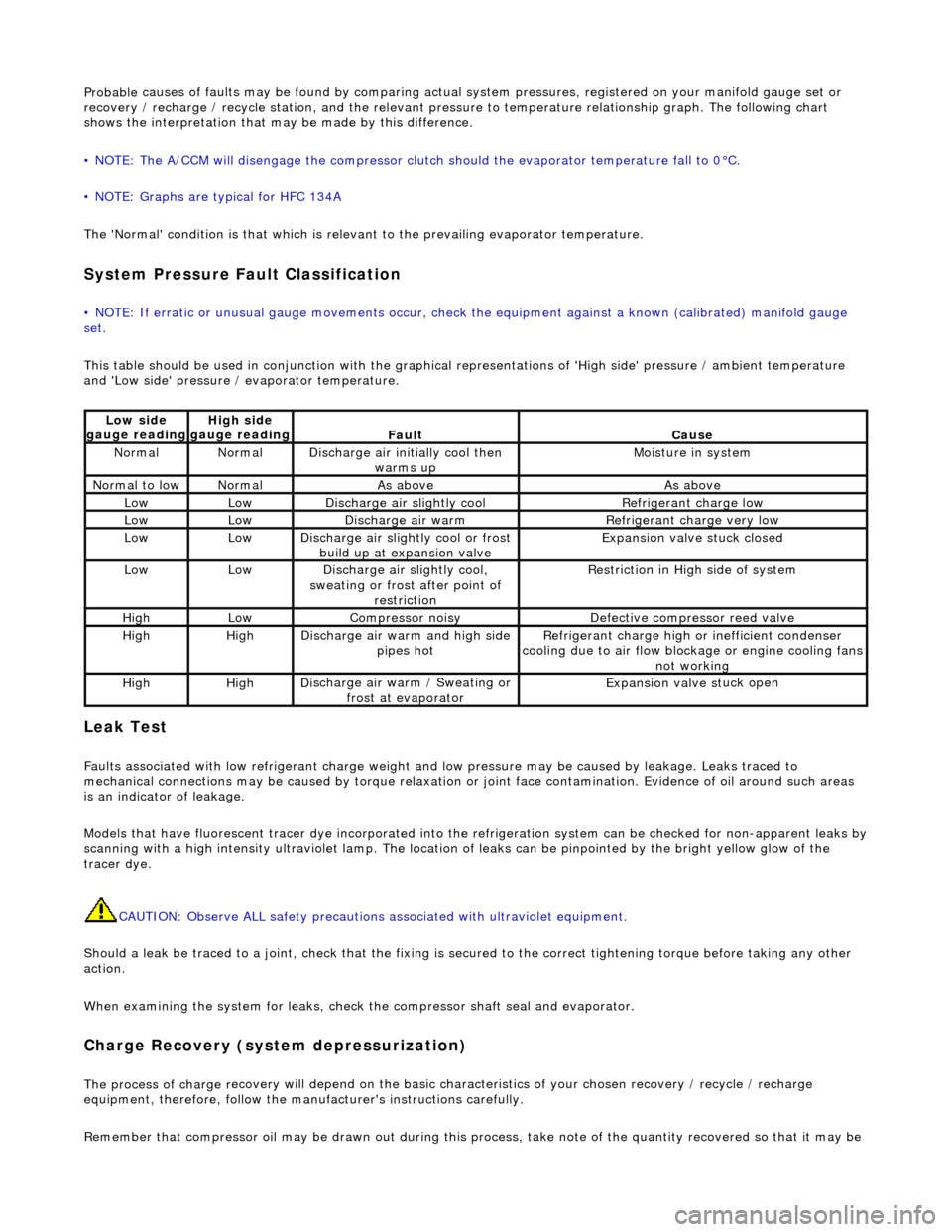
Probable
causes of faults may be found by comparing actual
system pressures, registered on your manifold gauge set or
recovery / recharge / recycle station, and the relevant pressure to temperature relationship graph. The following chart
shows the interpretation that ma y be made by this difference.
• NOTE: The A/CCM will disengage the compressor clutch should the evaporator temperature fall to 0°C.
• NOTE: Graphs are typical for HFC 134A
The 'Normal' condition is that which is relevant to the prevailing evaporator temperature.
System Pressure Fault Classification
• NOTE
: If erratic or unusual gauge move
ments occur, check the equipment against a known (calibrated) manifold gauge
set.
This table should be used in conjunction with the graphical representations of 'High side' pressure / ambient temperature
and 'Low side' pressure / evaporator temperature.
Leak
Test
F
a
ults associated with low re
frigerant charge weight and low pressure ma y be caused by leakage. Leaks traced to
mechanical connections may be caused by to rque relaxation or joint face contamination. Evidence of oil around such areas
is an indicator of leakage.
Models that have fluorescent tracer dye incorporated into the refrigeration system can be checke d for non-apparent leaks by
scanning with a high intensity ultraviolet lamp. The location of leaks can be pinpointed by the bright yellow glow of the
tracer dye.
CAUTION: Observe ALL safety precautions associated with ultraviolet equipment.
Should a leak be traced to a joint, check that the fixing is secured to the correct tightening torque before taking any other
action.
When examining the system for leaks, chec k the compressor shaft seal and evaporator.
Charge Re
covery (system depressurization)
The process of
charge r
ecovery will depe
nd on the basic characteristics of your chosen recovery / recycle / recharge
equipment, therefore, follow the manu facturer's instructions carefully.
Remember that compressor oil may be drawn out during this process, take note of the quantity recovered so that it may be
Lo
w side
gauge reading
High s i
de
gauge reading
Fau l
t
Cause
No
r
mal
No
r
mal
Di
sc
harge air initially cool then
warms up
Mois
ture in system
N
ormal
to low
No
r
mal
As aboveAs above
LowLowD
i
scharge air slightly cool
Ref
r
igerant charge low
LowLowDi
scharge air warm
Refr
igerant charge very low
LowLowDi
scharge air slightly cool or frost
build up at expansion valve
Expansion valve st
uck closed
LowLowDi
scharge air slightly cool,
sweating or frost after point of restriction
Restri
ction in High side of system
HighLowCompressor noisyDe
fe
ctive compressor reed valve
HighHighD
i
scharge air warm and high side
pipes hot
Refri
gerant charge high or inefficient condenser
cooling due to air flow blockage or engine cooling fans
not working
HighHighD i
scharge air warm / Sweating or
frost at evaporator
Expans ion valve st
uck open
Page 1759 of 2490
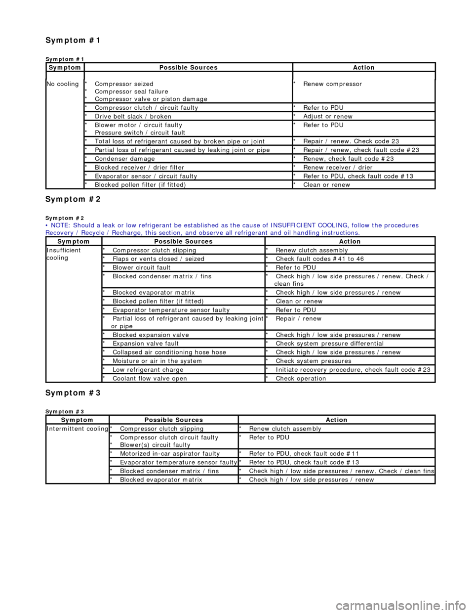
Sym
ptom #2
Sy
mptom #2
Sym
ptom #3
Sy
mptom #3
No
cooling
Compressor sei
zed
Compressor seal failure
Compressor valve or piston damage
*
*
*
R
enew compressor
*
Compressor cl
utch / circuit faulty
*
R
efer to PDU
*
D
rive belt slack / broken
*
Adjust or r
enew
*
B
lower motor / circuit faulty
Pressure switch / circuit fault
*
*
R
efer to PDU
*
Total l
oss of refrigerant caused by broken pipe or joint
*
Repair / renew. Check code 2
3
*
P
artial loss of refrigerant caused by leaking joint or pipe
*
R
epair / renew, check fault code #23
*
Conden
ser damage
*
Re
new, check fault code #23
*
Bl
ocked receiver / drier filter
*
R
enew receiver / drier
*
Evaporator senso
r / circuit faulty
*
R
efer to PDU, check fault code #13
*
Bl
ocked pollen filter (if fitted)
*
Cle
an or renew
*
• NOTE: Should a leak or low refrigerant be established as the cause of INSUFFICIENT COOL ING, follow the procedures
Recovery / Recycle / Recharge, this section, and ob serve all refrigerant and oil handling instructions.
Sy
mptom
Possib
le Sources
Acti
on
Insuffi
cient
cooling
Compre
ssor clutch slipping
*
R
enew clutch assembly
*
Fl
aps or vents closed / seized
*
Check f
ault codes #41 to 46
*
Bl
ower circuit fault
*
R
efer to PDU
*
Bl
ocked condenser matrix / fins
*
Check hig
h / low side pr
essures / renew. Check /
clean fins
*
Bl
ocked evaporator matrix
*
Check hig
h / low side
pressures / renew
*
Bl
ocked pollen filter (if fitted)
*
Cle
an or renew
*
Evaporator temp
erat
ure sensor faulty
*
R
efer to PDU
*
P
artial loss of refrigerant caused by leaking joint
or pipe
*
R
epair / renew
*
Blocked expan
sion valve
*
Check hig
h / low side
pressures / renew
*
Expans
ion valve fault
*
Chec
k system pres
sure differential
*
C
ollapsed air conditioning hose hose
*
Check hig
h / low side
pressures / renew
*
Moi
sture or air in the system
*
Chec
k system pressures
*
Low r
efrigerant charge
*
Initiate recovery
procedure, check fault code #23
*
Coo
lant flow valve open
*
Chec
k operation
*
Sy
mptom
Possib
le Sources
Acti
on
Int
ermittent cooling
Compre
ssor clutch slipping
*
R
enew clutch assembly
*
Compressor cl
utch circuit faulty
Blower(s) circuit faulty
*
*
R
efer to PDU
*
Motorized in-car aspirator faulty
*
R
efer to PDU, check fault code #11
*
Evaporator temp
erature sensor faulty
*
R
efer to PDU, check fault code #13
*
Bl
ocked condenser matrix / fins
*
Check hig
h / low side pressures / renew. Check / clean fins
*
Bl
ocked evaporator matrix
*
Check hig
h / low side
pressures / renew
*
Sym
ptom #1
Sy
mptom #1
Sy
mptom
Possib
le Sources
Acti
on
Page 1785 of 2490
Engine speed (valve closed with the engine not running) Demand (set) temperature In-car temperature sensor Solar sensor
Re-heating of the refrigerated air is contro lled by the time that the water valve is open (i.e. not energised) over a six secon d
interval. The duty cycle of the water valve, the time open / time closed, is controlled by the A/CCM.
Maximum heating demand will cause the water valve to be fu lly open (not energised) to allow maximum coolant flow
through the heater matrix.
At Maximum cooling, the water va lve will be fully closed (energised) to prevent hot (engine temperature) coolant entering
the heater circuit; the pump however will continue to circulate coolant through both the heater matrix and water valve
bypass.
The water valve defaults open when the ignition is OFF.
Under engine stall conditions, when ignition is ON, the water valve will be open.
Water Pump Assembly
Located in the same area as the water valve, the water pump continually circulates coolant through the heater matrix
except when the conditions below apply:
The engine coolant is below 16°C. The ignition is OFF. Under engine stall conditions, when ignition is ON. Control panel OFF
Non return valves
The heater bypass hose has a non-return valve, located between the engine feed and return hoses. The valve prevents the
water pump from recirculating coolant fro m the heater at low engine speeds.
The flow indicator arrow embossed on the valve bo dy MUST point towards the coolant header tank.
CAUTION: Coolant flow will be compromi sed if either valve is fitted incorrectly. Observe the correct direction.
A second non-return valve is located betw een the water pump and water valve. This valve prevents hot coolant from flowing
into the heater with the engine switched off. The flow indicator arrow MUST point towards the water pump.
Heater feed and return hoses
The heater feed and return hoses are connected to the engine feed and return hoses by 'Quick-Fit' connection unions. The
feed hose has a Norma R20 connector and the return hose a Norma push and seal connector. The coolant system bleed
joints have Cobra clamps. All remaining hose connections have spring band hose clamps.
The engine feed hose is connected to the engine bypass hous ing and the engine return hose is connected to the engine
water pump.
Clamp Identification
Page 1791 of 2490
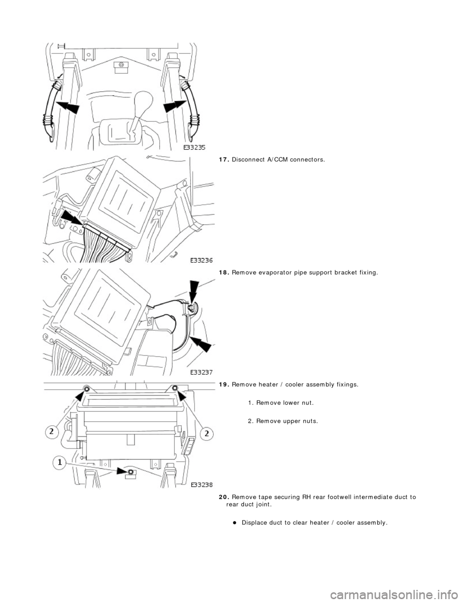
17. Disconnect A/CCM connectors.
18. Remove evaporator pipe support bracket fixing.
19. Remove heater / cooler assembly fixings.
1. Remove lower nut.
2. Remove upper nuts.
20. Remove tape securing RH rear footwell intermediate duct to
rear duct joint.
Displace duct to clear heater / cooler assembly.
Page 1792 of 2490
Installation
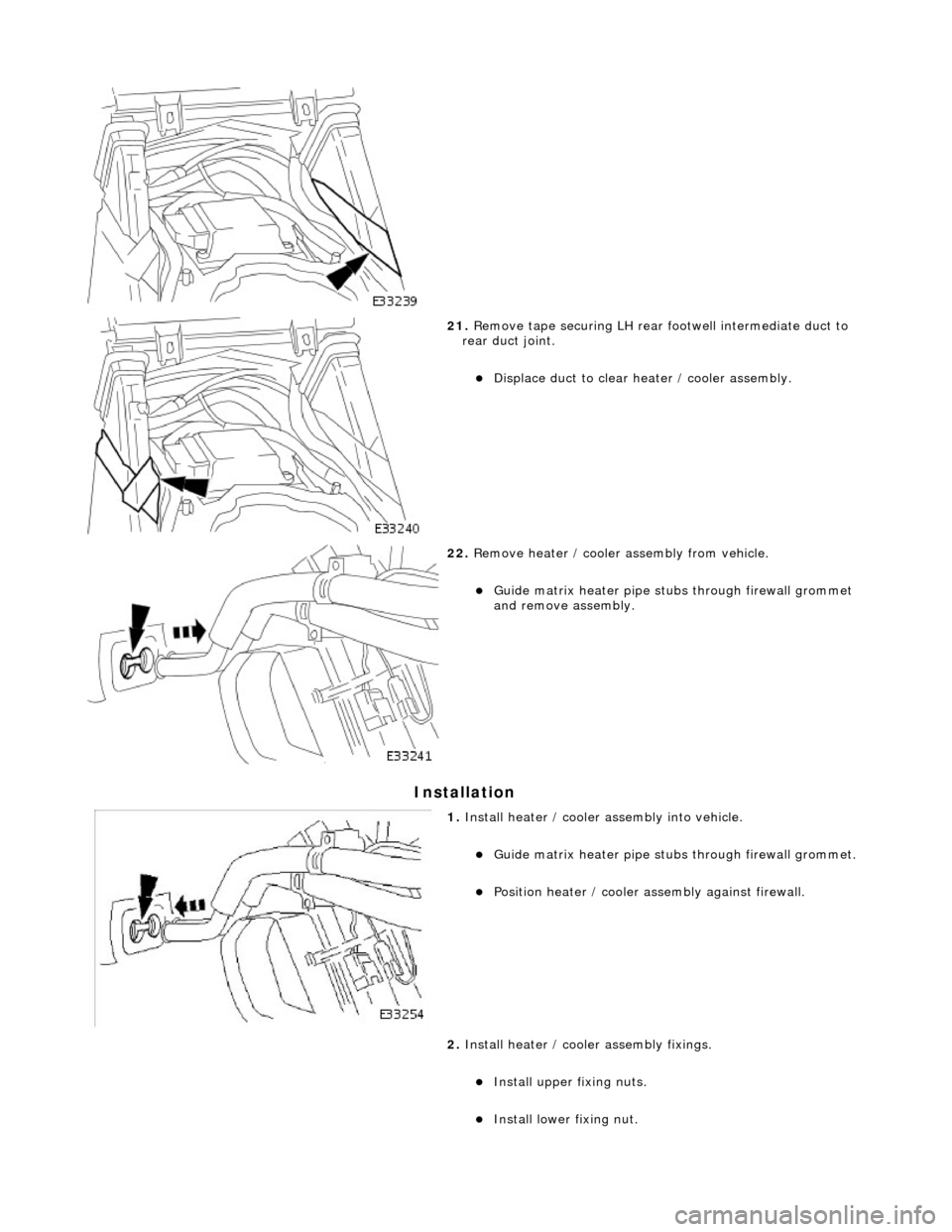
21. Remove tape securing LH rear footwell intermediate duct to
rear duct joint.
Displace duct to clear heater / cooler assembly.
22. Remove heater / cooler assembly from vehicle.
Guide matrix heater pipe stubs through firewall grommet
and remove assembly.
1. Install heater / cooler assembly into vehicle.
Guide matrix heater pipe stubs through firewall grommet.
Position heater / cooler as sembly against firewall.
2. Install heater / cooler assembly fixings.
Install upper fixing nuts.
Install lower fixing nut.