Page 26 of 2490
Side Turn Signal Lamp (86.41.41)
Side Turn Signal Lamp Bulb (86. 41.42)
417‐02
:
Interior Lighting
Specification
Description and Operation
Interior Lighting
Diagnosis and Testing
Interior Lighting
Removal and Installation
Door Courtesy Lamp (86.40.38)
Door Courtesy Lamp Bulb (86.40.47)
Door Courtesy Lamp Lens (86.40.35)
Glove Co
mpartment Lamp (86.45.08)
Luggage Compartment Lamp (86.45.16)
Vanity Mirror Lamp (76.10.50)
417‐04: Daytime Running Lamps (DRL)
Description and Operation
Daytime Running Lamps (DRL)
Diagnosis and Testing
Daytime Running Lamps (DRL)
418: Electrical Distribution
418‐00: Module Communications Network
Description and Operation
Communications Ne
twork
Removal
and Installation
Battery
Junction Box (BJB) (86.70.69)
Central
Junction Box (CJB) (86.70.72)
Front
Auxiliary Junction Box (86.70.73)
Rear
Auxiliary Junction Box (86.70.74)
418 ‐02: Wiring Harnesses
Description and Operati
on
Wiring Harness
General Procedures
Wiring Harness Repair
Page 1846 of 2490
Control Components - Remote Climate Control ModuleLHD RWD
Removal and Installation
Removal
1. Position the driver's seat fully rearward
2. Glove box, 76.52.03
3. Remove the duct - passenger footwell
Remove the nut (1) duct to blower
4. Disconnect the BPM multiplug
Slacken the bolt (1), noting that it is captive in the
multiplug
Disconnect the multiplug
5. Remove the BPM
1. Remove the fixings (3), BPM to fascia reinforcement
2. Remove the BPM
6. Slacken the A/CCM upper fixing using a 'Snap-On' SDP 11
stubby screwdriver, or similar
Page 1961 of 2490
Interior Lighting -
Bulbs
DescriptionCapacityType
Door Guard / Puddle Lamps12V 5WCapless Long Life
Glovebox Lamp12V 4WBayonet Long Life
Luggage Compartment Lamp12V 5WCapless Long Life
Roof Console Central Courtesy Lamp12V 5WCapless Long Life
Roof Console Map Lamp12V 6WCapless
Rear Quarter Courtesy Lamp (lower section)12V 5WCapless Long Life
Rear Quarter Reading Lamp (upper section)12V 6WCapless Long Life
Sun Visor Vanity Mirror Lamp12V 1.2WCapless 286
Page 1962 of 2490

Interior Lighting - Interior Lighting
Description and Operation
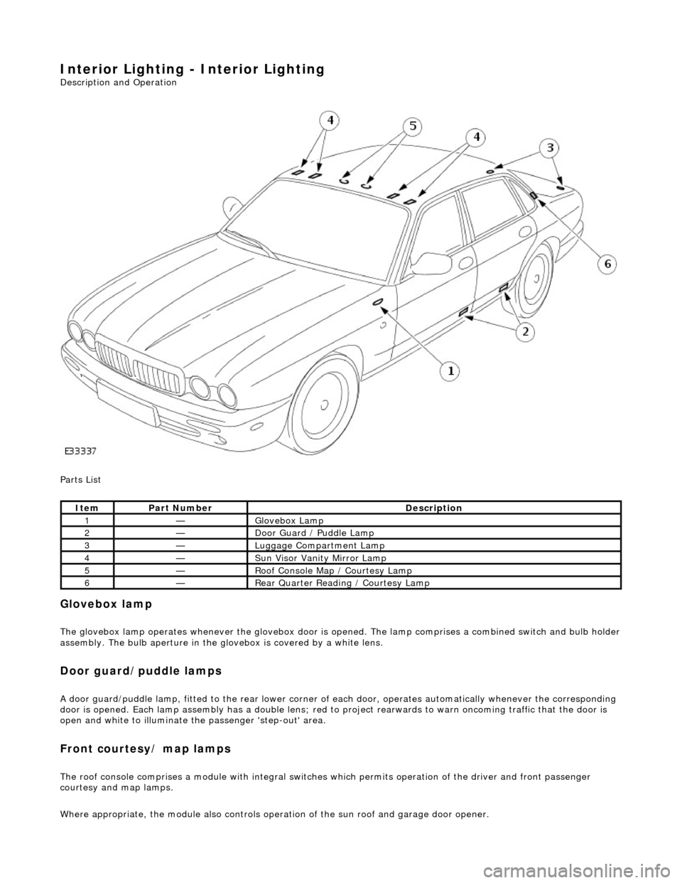
Parts List
Glovebox lamp
The glovebox lamp operates whenever the glovebox door is opened. The lamp comprises a combined switch and bulb holder assembly. The bulb aperture in the glovebox is covered by a white lens.
Door guard/puddle lamps
A door guard/puddle lamp, fitted to the rear lower corner of each door, operates automatically whenever the corresponding
door is opened. Each lamp assembly has a double lens; red to project rearwards to warn oncoming traffic that the door is
open and white to illuminate the passenger 'step-out' area.
Front courtesy/ map lamps
The roof console comprises a module with integral switches which permits operation of the dr iver and front passenger
courtesy and map lamps.
Where appropriate, the module also controls operation of the su n roof and garage door opener.
ItemPart NumberDescription
1—Glovebox Lamp
2—Door Guard / Puddle Lamp
3—Luggage Compartment Lamp
4—Sun Visor Vanity Mirror Lamp
5—Roof Console Map / Courtesy Lamp
6—Rear Quarter Reading / Courtesy Lamp
Page 1963 of 2490

Rear courtesy/ reading lamps
Each rear quarter of the passenger compartment is fitted with combined lighting units comprising; a rear courtesy lamp and
reading lamp. The courtesy lamps operate automatically whenever a rear door is opened; the reading lamps function when
the integral switches are operated by occupants of the vehicle.
Trunk lamps
The trunk trim panel is fitted with lamps which operate auto matically whenever the trunk lid is opened; the switch is
incorporated within the latch mechanism.
Vanity mirror lamps
The vanity mirror lamps, two on each sun visor, operate auto matically when the mirror flap is opened, provided the sun
visor spindle is engage d in the stowage clip.
Operation
The BPM provides an enable signal for the glovebox, vanity mirror, trunk lid and map lamps. Actuation of the relevant
switch provides an earth path to the lamp.
The rear passenger reading lamps receive a supply di rect from fuse F10 in the RH heelboard fuse-box.
The front and rear courtesy lamps have separa te fade functions controlled by the BPM.
The door hazard / puddle lamps are controll ed locally by the relevant Door Module.
Fault analysis must be undertaken using the PDU, refer to Diagnosis and Testing.
Refer to the relevant Electrical Guid e for details of circuit operation.
Page 1968 of 2490
Interior Lighting - Glove Compartment Lamp
Removal and Installation
Removal
Installation
1.
Open glovebox lid.
2. Carefully release and remove plas tic lens from glovebox light.
3. Remove bulb from glovebox light.
4. Release light/switch assembly retaining tangs and partially
withdraw assembly from glovebox exterior.
5. Position light/switch assembly for access, disconnect harness
spade connectors and remove assembly from glovebox
aperture.
1. Position light/switch assembly at glovebox aperture and
connect harness spade connectors.
2. Install assembly in aperture, en suring that retaining tangs are
fully seated.
3. Install bulb in light/switch assembly and check that harness
leads are clear of bulb.
4. Install plastic lens to light/switch assembly.
5. Close glovebox lid.
Page 2008 of 2490

Driver Door Module (DDM)
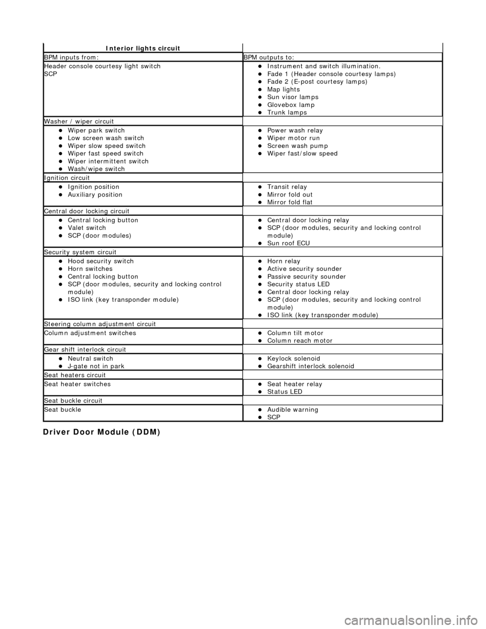
Interior lights circuit
BPM inputs from: BPM outputs to:
Header console courtesy light switch
SCPInstrument and switch illumination. Fade 1 (Header console courtesy lamps) Fade 2 (E-post courtesy lamps) Map lights Sun visor lamps Glovebox lamp Trunk lamps
Washer / wiper circuit
Wiper park switch Low screen wash switch Wiper slow speed switch Wiper fast speed switch Wiper intermittent switch Wash/wipe switch
Power wash relay Wiper motor run Screen wash pump Wiper fast/slow speed
Ignition circuit
Ignition position Auxiliary position Transit relay Mirror fold out Mirror fold flat
Central door locking circuit
Central locking button Valet switch SCP (door modules)
Central door locking relay SCP (door modules, security and locking control
module)
Sun roof ECU
Security system circuit
Hood security switch Horn switches Central locking button SCP (door modules, security and locking control
module)
ISO link (key transponder module)
Horn relay Active security sounder Passive security sounder Security status LED Central door locking relay SCP (door modules, security and locking control
module)
ISO link (key transponder module)
Steering column adjustment circuit
Column adjustment switchesColumn tilt motor Column reach motor
Gear shift interlock circuit
Neutral switch J-gate not in park Keylock solenoid Gearshift interlock solenoid
Seat heaters circuit
Seat heater switchesSeat heater relay Status LED
Seat buckle circuit
Seat buckleAudible warning SCP
Page 2017 of 2490
Multifunction Electronic Modules - Multifunction Electronic Module
Removal and Installation
Removal
Installation
1.
Switch ON ignition. Move pass enger seat fully rearwards.
Switch OFF ignition.
2. Disconnect battery ground cable; refer to 86.15.19.
3. Remove glove box; refer to 76.52.03.
4. Remove body processor module.
1. Release bolt and discon nect harness connector.
2. Remove three nuts which secure module to fascia.
3. Remove module.
1. Installation is reverse of removal.
2. Reconnect battery ground cable; refer to 86.15.15.
3. Synchronize ECM, KTM, BPM using PDU.